Telit Communications S p A GM862G Quad-Band GSM/GPRS module - Type: GM862-GPS User Manual TELIT TRIZIUM
Telit Communications S.p.A. Quad-Band GSM/GPRS module - Type: GM862-GPS TELIT TRIZIUM
Contents
- 1. Users Manual Hardware Guide
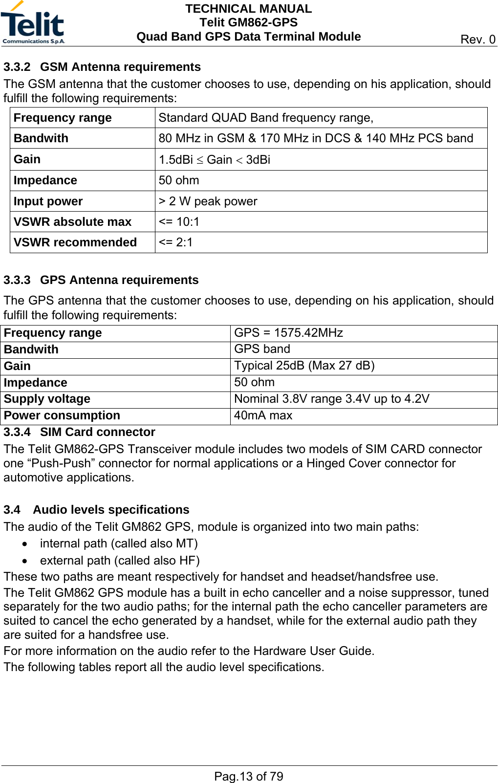
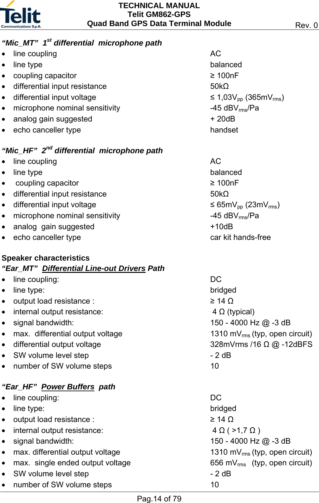
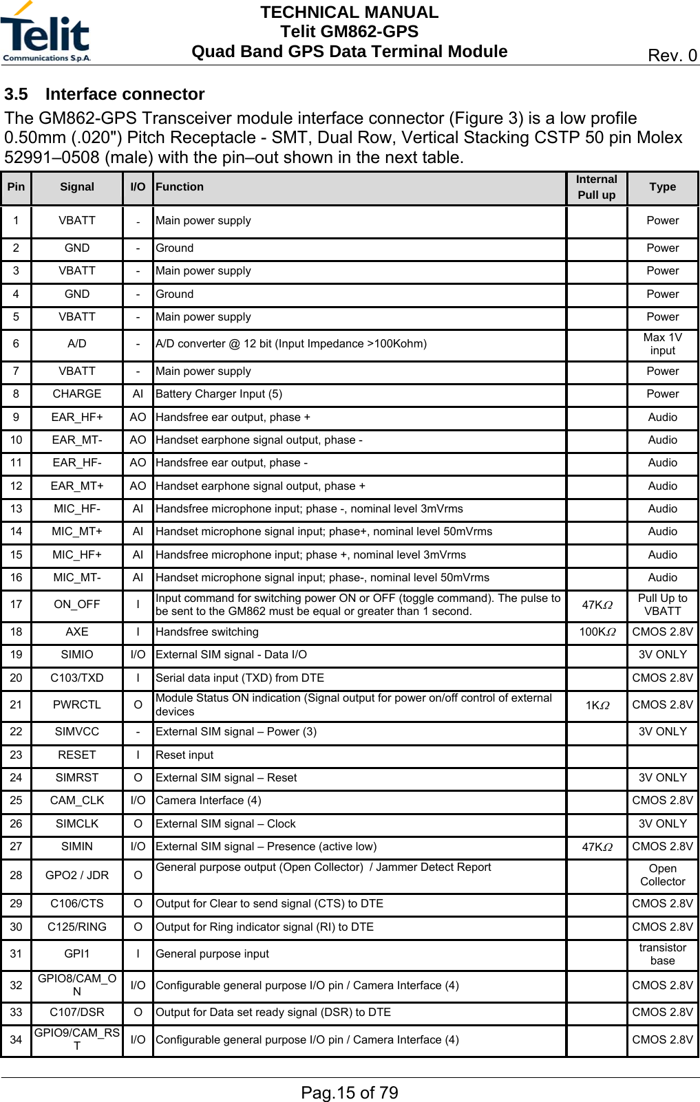
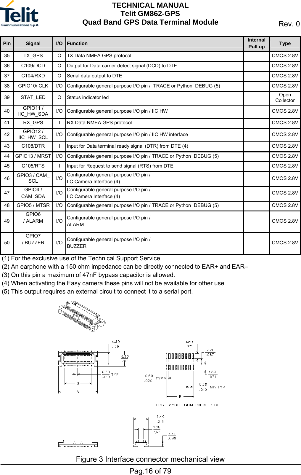
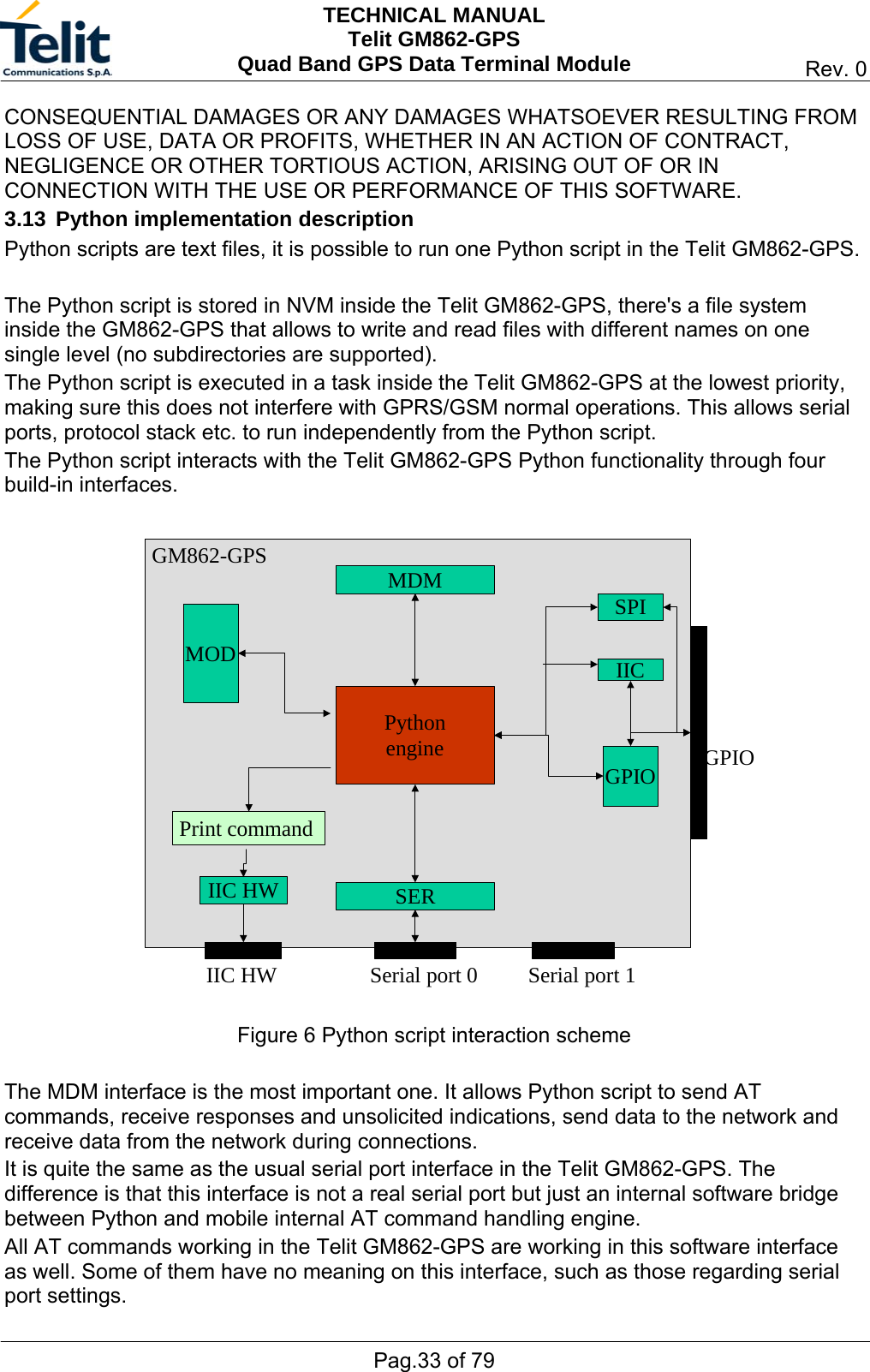
- 2. Users Manual Technical Guides
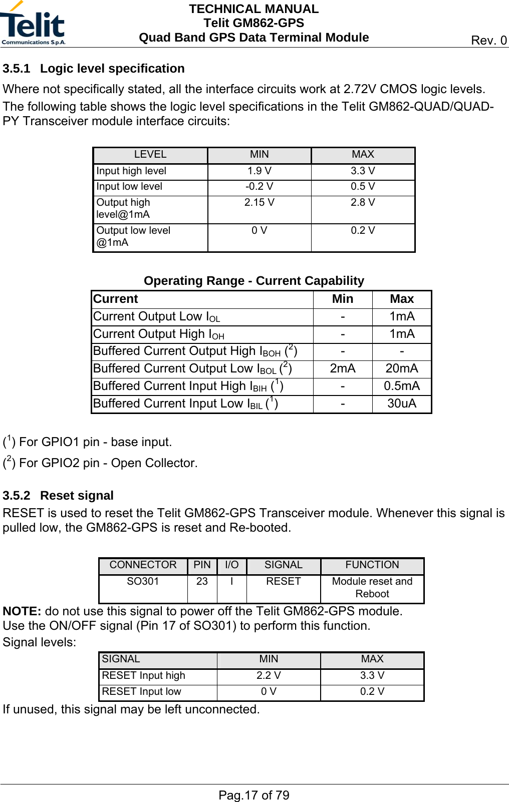
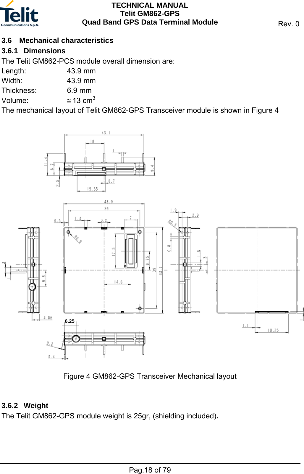
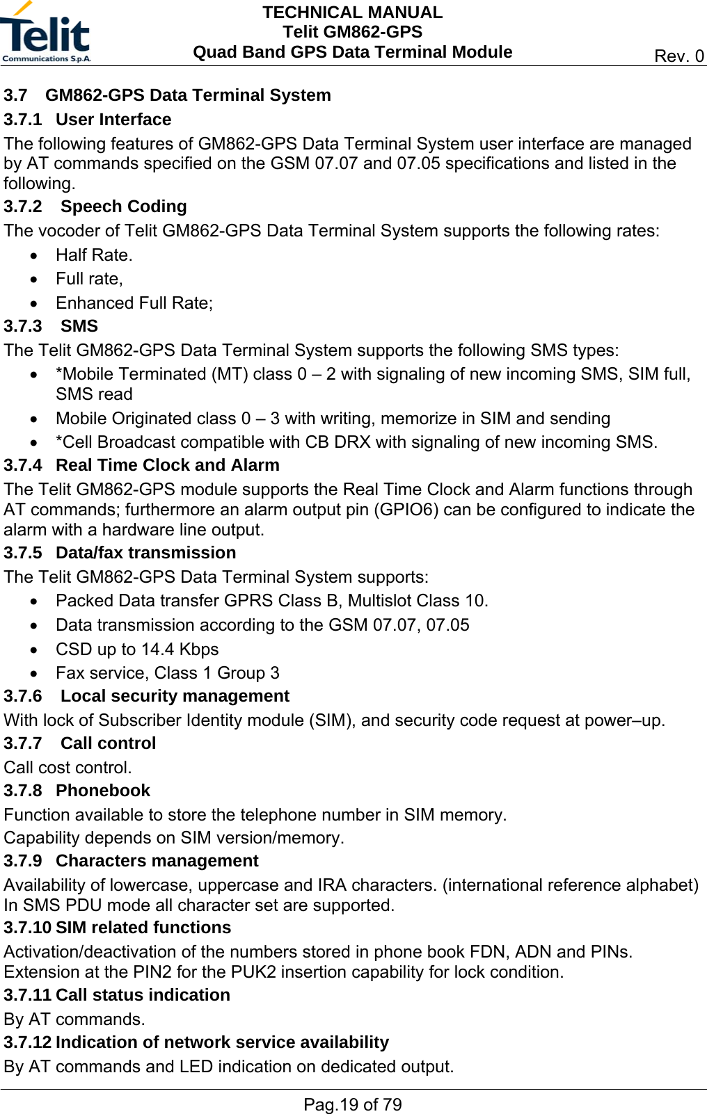
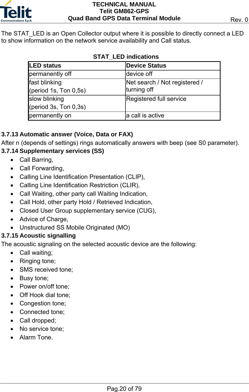
Users Manual Technical Guides