Teles Informationstechnologien CDMA32VOIPUS Cellular/PCS CDMA Gateway User Manual TELES iGATE V16 2
Teles AG Informationstechnologien Cellular/PCS CDMA Gateway TELES iGATE V16 2
UserManual.wiki
>
Teles Informationstechnologien
>
CDMA32VOIPUS User Manual
Users Manual
Navigation menu
Upload a User Manual
Namespaces
Wiki Guide
HTML
PDF
Info
Views
User Manual
Discussion / Help
Navigation
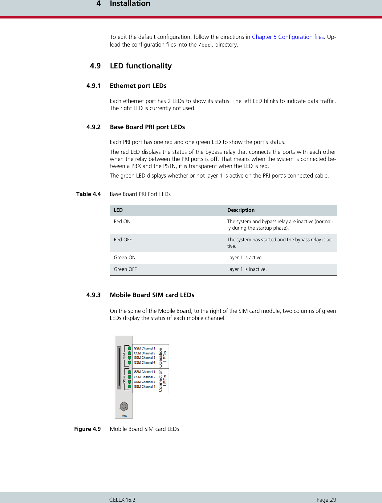
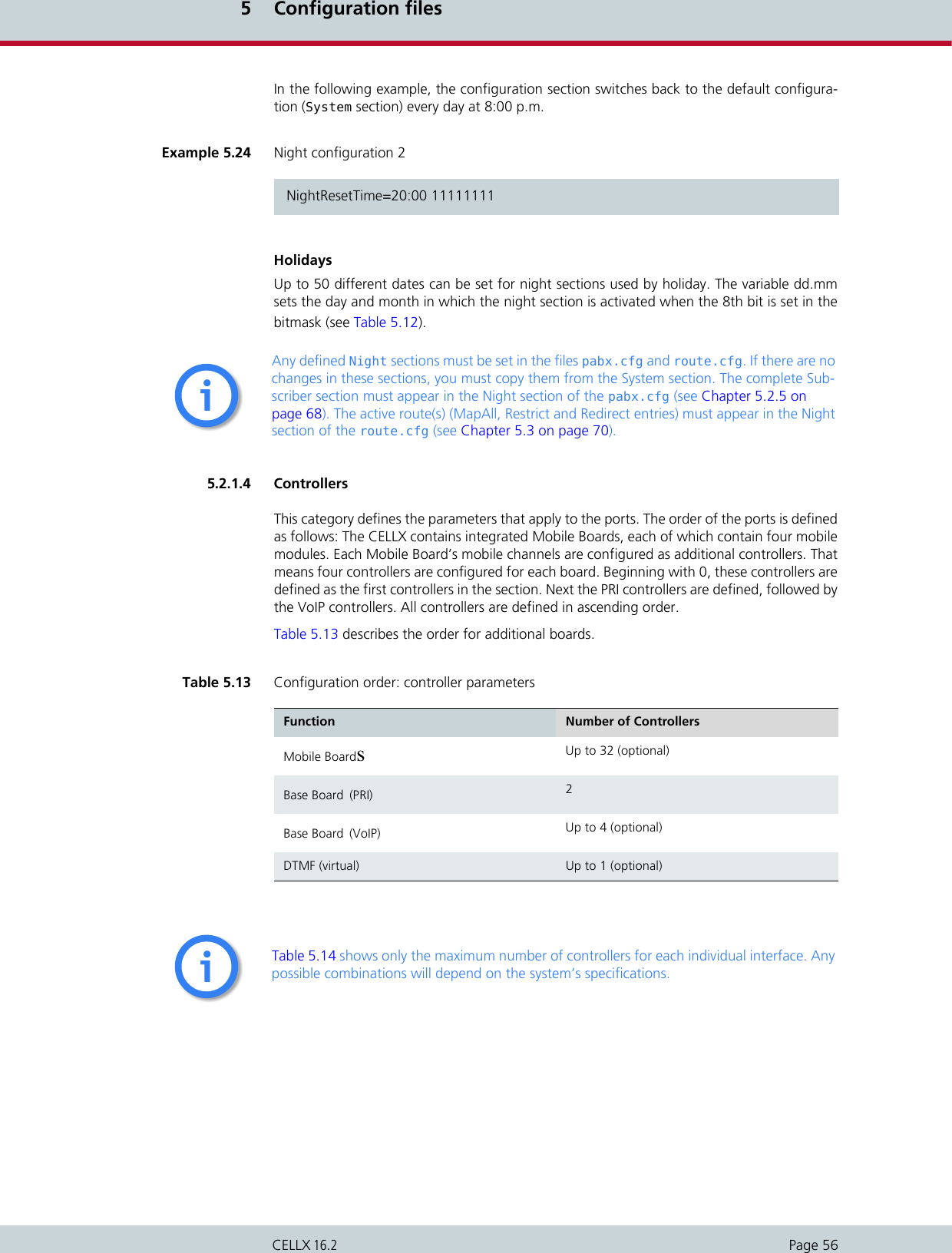
![Page 2CELLX 16.25 Configuration files . . . . . . . . . . . . . . . . . . . . . . . . . . . . . . . . . . 365.1 Configuration file ip.cfg . . . . . . . . . . . . . . . . . . . . . . . . . . . . . . . . . . . . . . . . . . . . . . . .385.1.1 System section configuration . . . . . . . . . . . . . . . . . . . . . . . . . . . . . . . . . . . . . . . . . . . .385.1.2 Ethernet interface configuration . . . . . . . . . . . . . . . . . . . . . . . . . . . . . . . . . . . . . . . . .395.1.3 GUI settings . . . . . . . . . . . . . . . . . . . . . . . . . . . . . . . . . . . . . . . . . . . . . . . . . . . . . . . . . .395.1.4 Bridge configuration. . . . . . . . . . . . . . . . . . . . . . . . . . . . . . . . . . . . . . . . . . . . . . . . . . .405.1.5 NAT configuration. . . . . . . . . . . . . . . . . . . . . . . . . . . . . . . . . . . . . . . . . . . . . . . . . . . . .405.1.6 PPPoE configuration . . . . . . . . . . . . . . . . . . . . . . . . . . . . . . . . . . . . . . . . . . . . . . . . . . .415.1.7 Firewall settings. . . . . . . . . . . . . . . . . . . . . . . . . . . . . . . . . . . . . . . . . . . . . . . . . . . . . . .425.1.8 Bandwidth control. . . . . . . . . . . . . . . . . . . . . . . . . . . . . . . . . . . . . . . . . . . . . . . . . . . . .445.1.9 DHCP server settings . . . . . . . . . . . . . . . . . . . . . . . . . . . . . . . . . . . . . . . . . . . . . . . . . . .465.1.10 DNSmasq settings . . . . . . . . . . . . . . . . . . . . . . . . . . . . . . . . . . . . . . . . . . . . . . . . . . . . .475.1.11 PPP configuration for mobile and ISDN dial-up . . . . . . . . . . . . . . . . . . . . . . . . . . . . .485.1.12 VLAN configuration. . . . . . . . . . . . . . . . . . . . . . . . . . . . . . . . . . . . . . . . . . . . . . . . . . . .495.1.13 Examples . . . . . . . . . . . . . . . . . . . . . . . . . . . . . . . . . . . . . . . . . . . . . . . . . . . . . . . . . . . .505.1.13.1 Default configuration . . . . . . . . . . . . . . . . . . . . . . . . . . . . . . . . . . . . . . . . . . . . . . . . . .505.1.13.2 Active ethernet bridge . . . . . . . . . . . . . . . . . . . . . . . . . . . . . . . . . . . . . . . . . . . . . . . . .505.1.13.3 Integrated DSL-router scenario for VoIP . . . . . . . . . . . . . . . . . . . . . . . . . . . . . . . . . . .515.1.13.4 VLAN scenario . . . . . . . . . . . . . . . . . . . . . . . . . . . . . . . . . . . . . . . . . . . . . . . . . . . . . . . .525.2 Configuration file pabx.cfg . . . . . . . . . . . . . . . . . . . . . . . . . . . . . . . . . . . . . . . . . . . . .525.2.1 System settings . . . . . . . . . . . . . . . . . . . . . . . . . . . . . . . . . . . . . . . . . . . . . . . . . . . . . . .525.2.1.1 Global Settings. . . . . . . . . . . . . . . . . . . . . . . . . . . . . . . . . . . . . . . . . . . . . . . . . . . . . . . .525.2.1.2 Log files . . . . . . . . . . . . . . . . . . . . . . . . . . . . . . . . . . . . . . . . . . . . . . . . . . . . . . . . . . . . .535.2.1.3 Night configuration. . . . . . . . . . . . . . . . . . . . . . . . . . . . . . . . . . . . . . . . . . . . . . . . . . . .555.2.1.4 Controllers . . . . . . . . . . . . . . . . . . . . . . . . . . . . . . . . . . . . . . . . . . . . . . . . . . . . . . . . . . .565.2.1.5 Subscribers . . . . . . . . . . . . . . . . . . . . . . . . . . . . . . . . . . . . . . . . . . . . . . . . . . . . . . . . . . .595.2.1.6 Global settings. . . . . . . . . . . . . . . . . . . . . . . . . . . . . . . . . . . . . . . . . . . . . . . . . . . . . . . .625.2.2 SMTP-client configuration . . . . . . . . . . . . . . . . . . . . . . . . . . . . . . . . . . . . . . . . . . . . . .655.2.3 Number portability settings . . . . . . . . . . . . . . . . . . . . . . . . . . . . . . . . . . . . . . . . . . . . .675.2.4 SNMP settings . . . . . . . . . . . . . . . . . . . . . . . . . . . . . . . . . . . . . . . . . . . . . . . . . . . . . . . .685.2.5 Time-controlled configuration settings . . . . . . . . . . . . . . . . . . . . . . . . . . . . . . . . . . . .685.2.6 .CASR2 settings . . . . . . . . . . . . . . . . . . . . . . . . . . . . . . . . . . . . . . . . . . . . . . . . . . . . . . .685.3 Configuration file route.cfg . . . . . . . . . . . . . . . . . . . . . . . . . . . . . . . . . . . . . . . . . . . . .705.3.1 Entries in the [System] section . . . . . . . . . . . . . . . . . . . . . . . . . . . . . . . . . . . . . . . . . . .705.3.1.1 Restrict . . . . . . . . . . . . . . . . . . . . . . . . . . . . . . . . . . . . . . . . . . . . . . . . . . . . . . . . . . . . . .705.3.1.2 MapAll . . . . . . . . . . . . . . . . . . . . . . . . . . . . . . . . . . . . . . . . . . . . . . . . . . . . . . . . . . . . . .725.3.1.3 Redirect . . . . . . . . . . . . . . . . . . . . . . . . . . . . . . . . . . . . . . . . . . . . . . . . . . . . . . . . . . . . .745.3.1.4 Setting the time-controlled sections . . . . . . . . . . . . . . . . . . . . . . . . . . . . . . . . . . . . . .755.3.2 VoIP profiles. . . . . . . . . . . . . . . . . . . . . . . . . . . . . . . . . . . . . . . . . . . . . . . . . . . . . . . . . .765.3.3 Gatekeeper profiles. . . . . . . . . . . . . . . . . . . . . . . . . . . . . . . . . . . . . . . . . . . . . . . . . . . .795.3.4 Registrar profiles . . . . . . . . . . . . . . . . . . . . . . . . . . . . . . . . . . . . . . . . . . . . . . . . . . . . . .805.3.5 Radius profiles . . . . . . . . . . . . . . . . . . . . . . . . . . . . . . . . . . . . . . . . . . . . . . . . . . . . . . . .816 Routing examples. . . . . . . . . . . . . . . . . . . . . . . . . . . . . . . . . . . 836.1 CELLX integration in an H.323 carrier network. . . . . . . . . . . . . . . . . . . . . . . . . . . . . .846.2 CELLX as a second-generation LCR with VoIP. . . . . . . . . . . . . . . . . . . . . . . . . . . . . . .857 Mobile configuration options . . . . . . . . . . . . . . . . . . . . . . . . . 877.1 Network-specific mobile routing . . . . . . . . . . . . . . . . . . . . . . . . . . . . . . . . . . . . . . . . .887.1.1 Routing decisions for calls to the mobile network . . . . . . . . . . . . . . . . . . . . . . . . . . .88](https://usermanual.wiki/Teles-Informationstechnologien/CDMA32VOIPUS/User-Guide-1599912-Page-4.png)
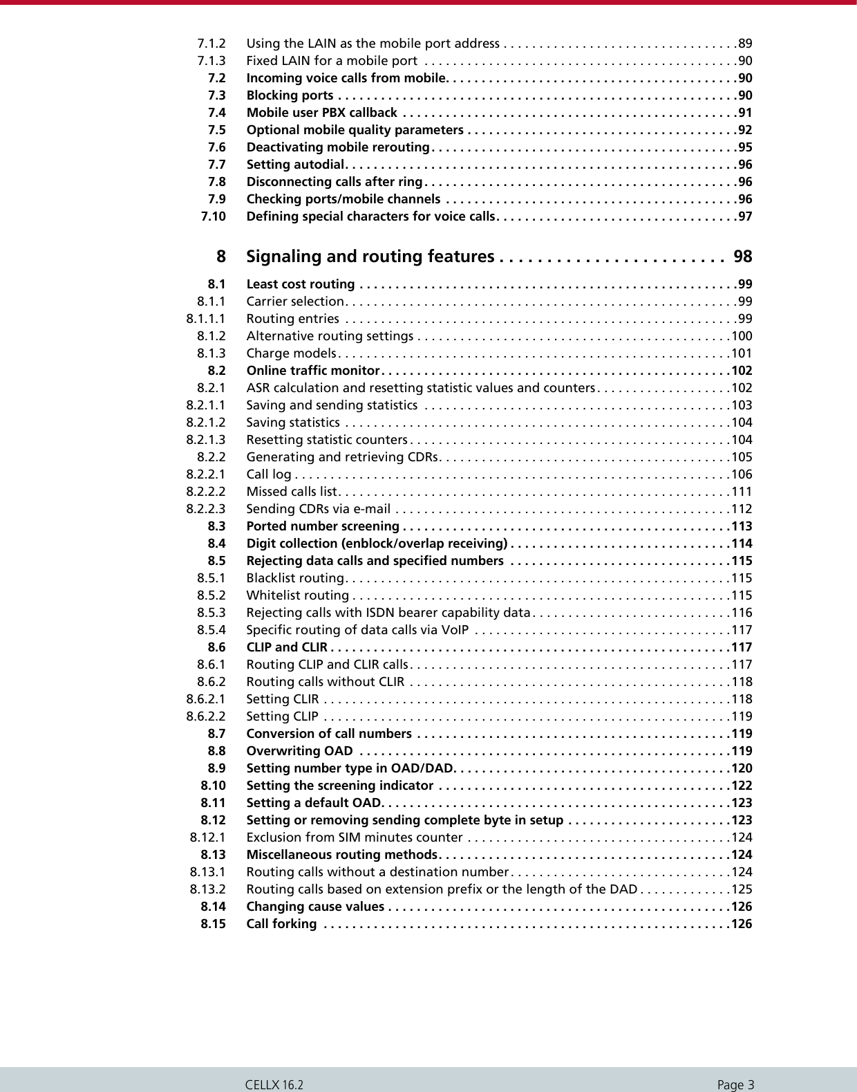

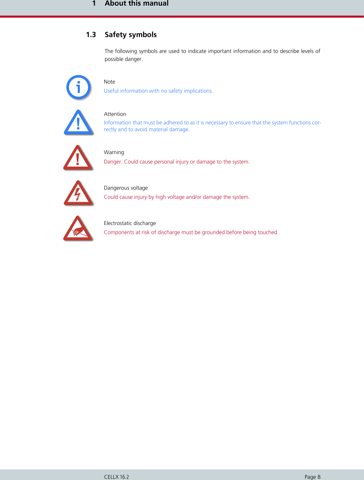
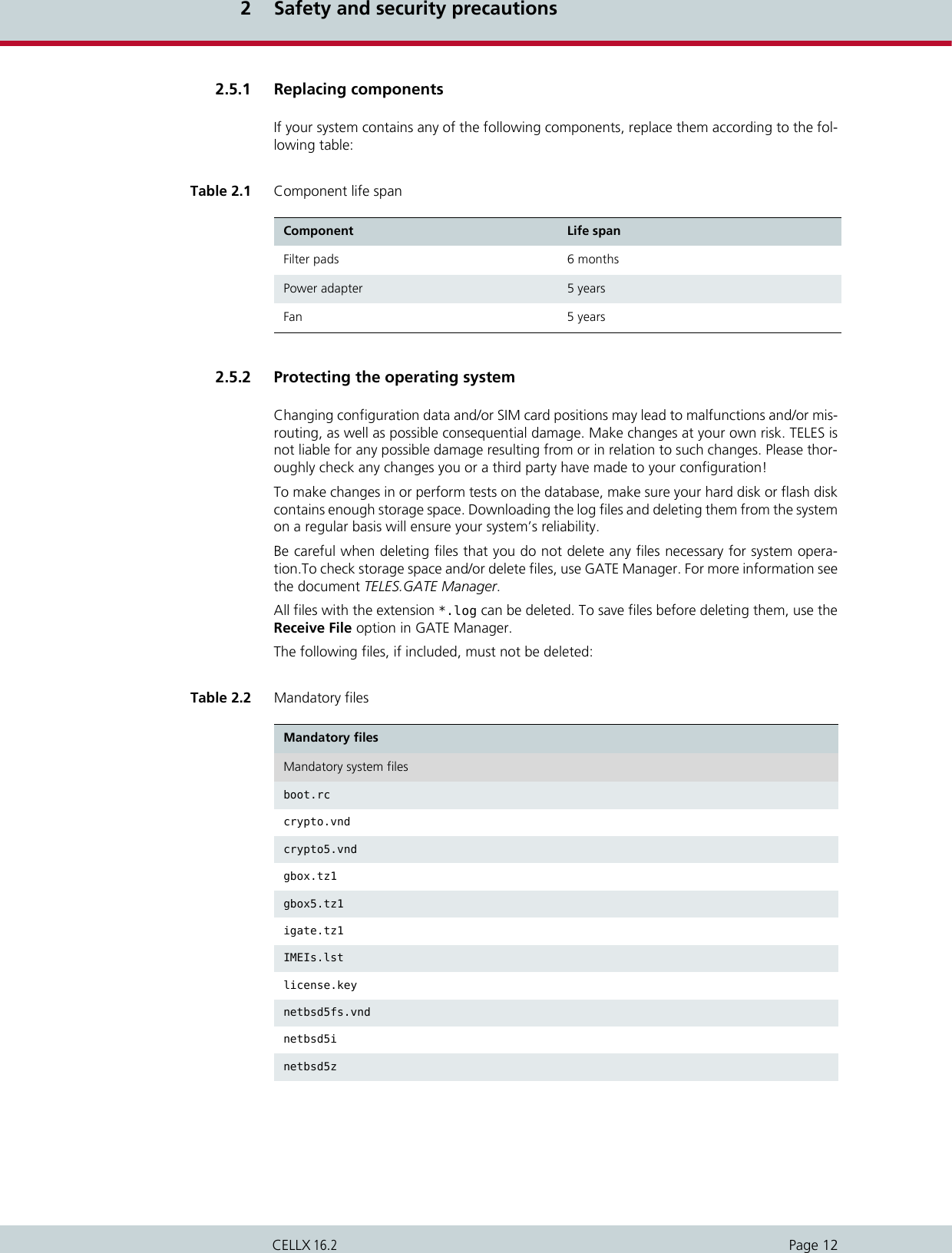
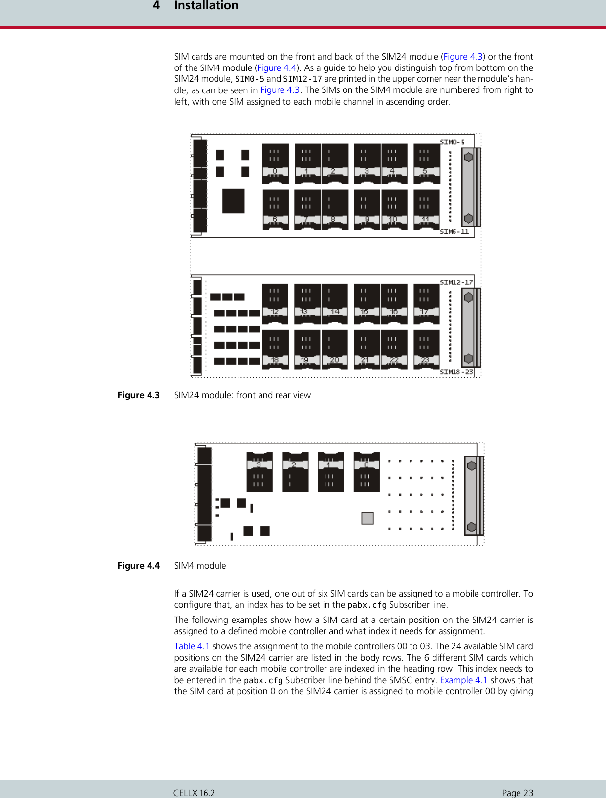
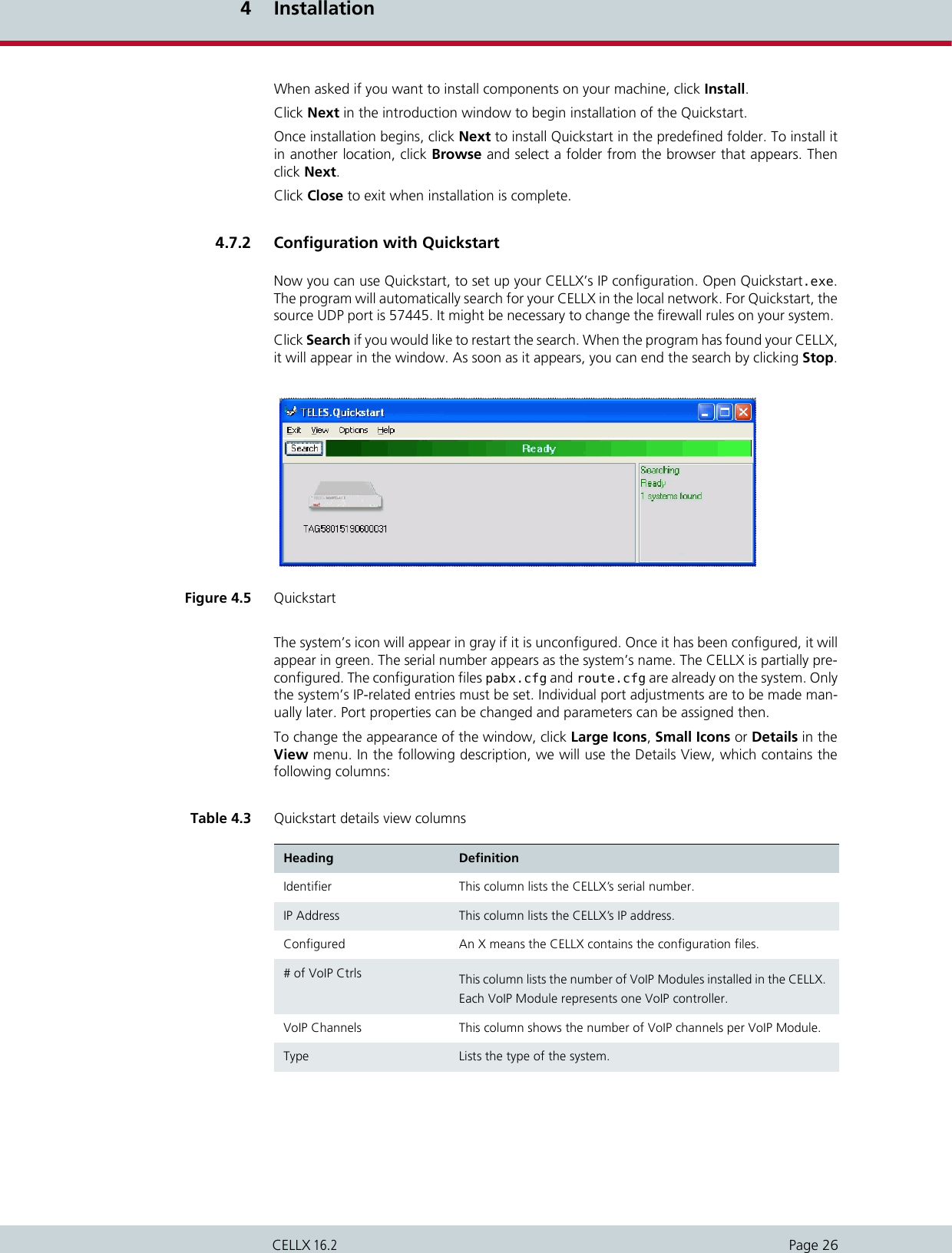
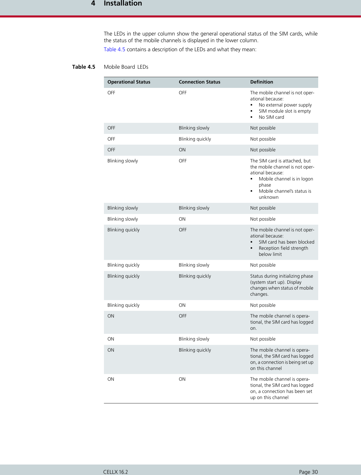
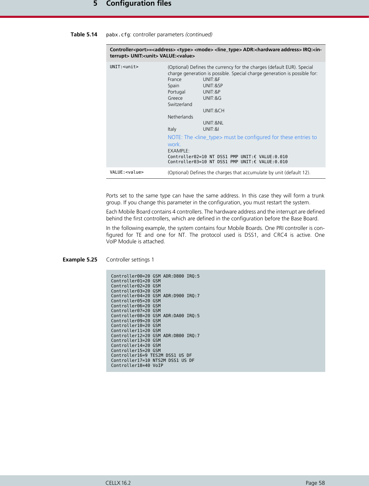
![4 InstallationPage 24CELLX 16.2it the index 1. The SIM card which is at position 1 on the SIM24 carrier is assigned to the mo-bile controller 01 by also giving it the index 1. SIM card number 10 on the SIM24 carrier isassigned to mobile controller 02 with the index 3. Analogously, SIM card number 11 is as-signed to mobile controller 03 with the index 3.The following corresponding example shows how SIM cards at position 4, 5, 6, and 7 on theSIM24 carrier are assigned to the mobile controller 08 to 11. They all get the index 2 in theSubscriber line.Table 4.1 SIM card assignment to mobile controllers 1 (SIM24 carrier)Index in Subscriber line 1 2 3 4 5 6Controller/Subscriber00 0 4 8 12 16 20Controller/Subscriber01 15 9 13 17 21Controller/Subscriber02 2610 14 18 22Controller/Subscriber03 3 7 11 15 19 23Example 4.1 SIM card assignment to mobile controllers 1 (SIM24 carrier)Subscriber00=TRANSPARENT GSM[0000,00000,+491770610000,1,1,1,SIM24] ALARMSubscriber01=TRANSPARENT GSM[0000,00000,+491770610000,1,1,1,SIM24] ALARMSubscriber02=TRANSPARENT GSM[0000,26202,+491770610000,3,1,1,SIM24] ALARM Subscriber03=TRANSPARENT GSM[0000,00000,+491770610000,3,1,1,SIM24] ALARMTable 4.2 SIM card assignment to mobile controllers 2 (SIM24 carrier)Index in Subscriber line 1 2 3 4 5 6Controller/Subscriber08 0 48121620Controller/Subscriber09 15913 17 21Controller/Subscriber10 2 610 14 18 22Controller/Subscriber11 3711 15 19 23Example 4.2 SIM card assignment to mobile controllers 2 (SIM24 carrier)Subscriber08=TRANSPARENT GSM[0000,00000,+491770610000,2,1,1,SIM24] ALARMSubscriber09=TRANSPARENT GSM[0000,00000,+491770610000,2,1,1,SIM24] ALARMSubscriber10=TRANSPARENT GSM[0000,26202,+491770610000,2,1,1,SIM24] ALARM Subscriber11=TRANSPARENT GSM[0000,00000,+491770610000,2,1,1,SIM24] ALARM](https://usermanual.wiki/Teles-Informationstechnologien/CDMA32VOIPUS/User-Guide-1599912-Page-26.png)
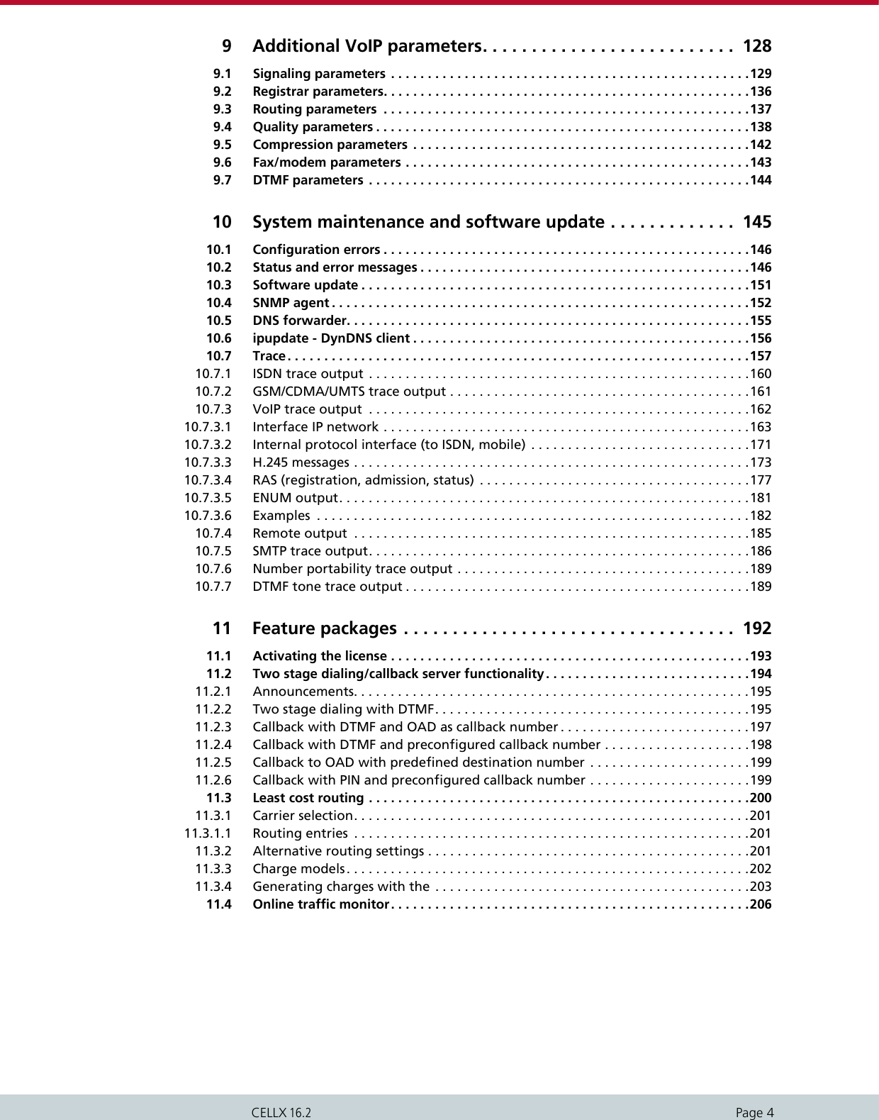
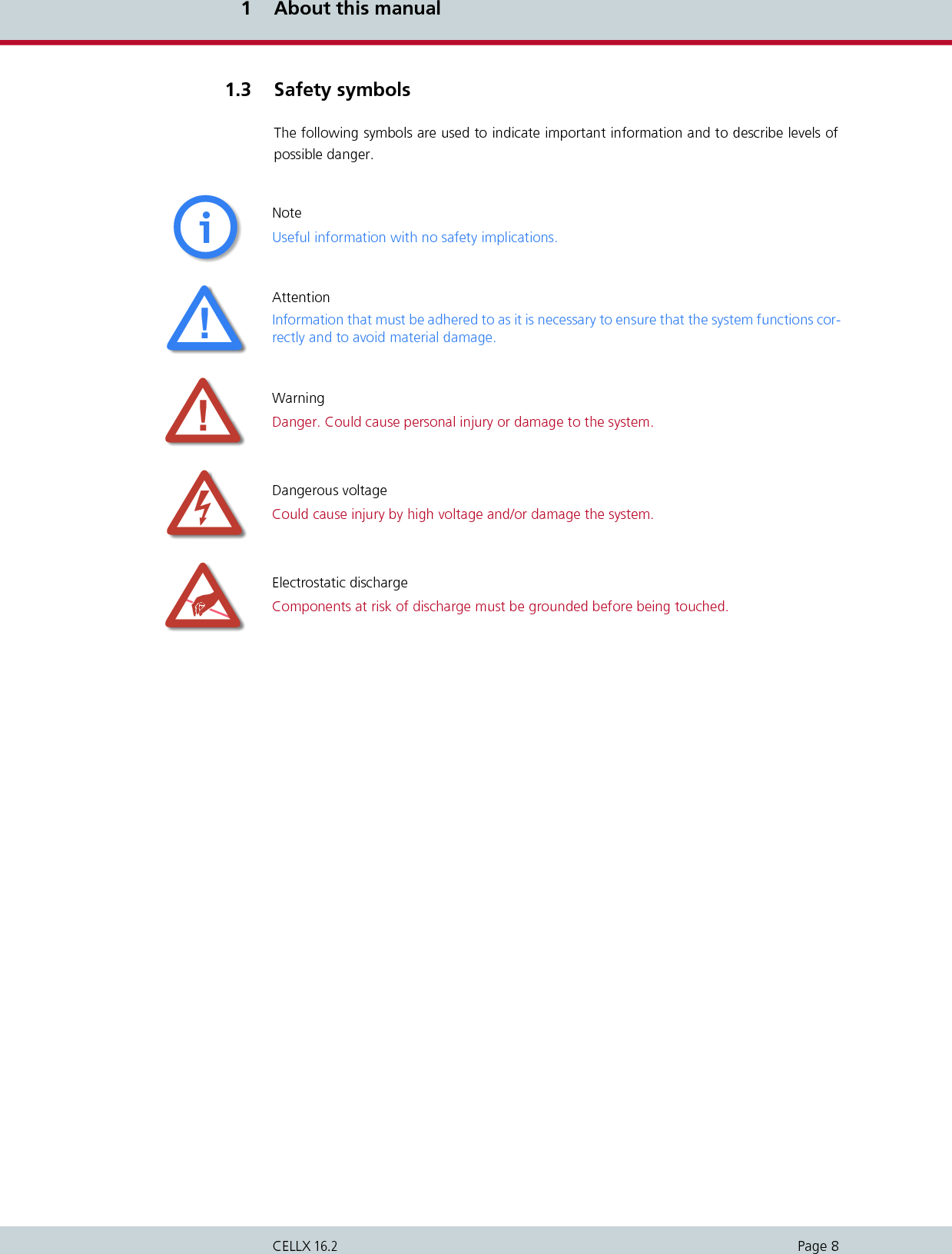
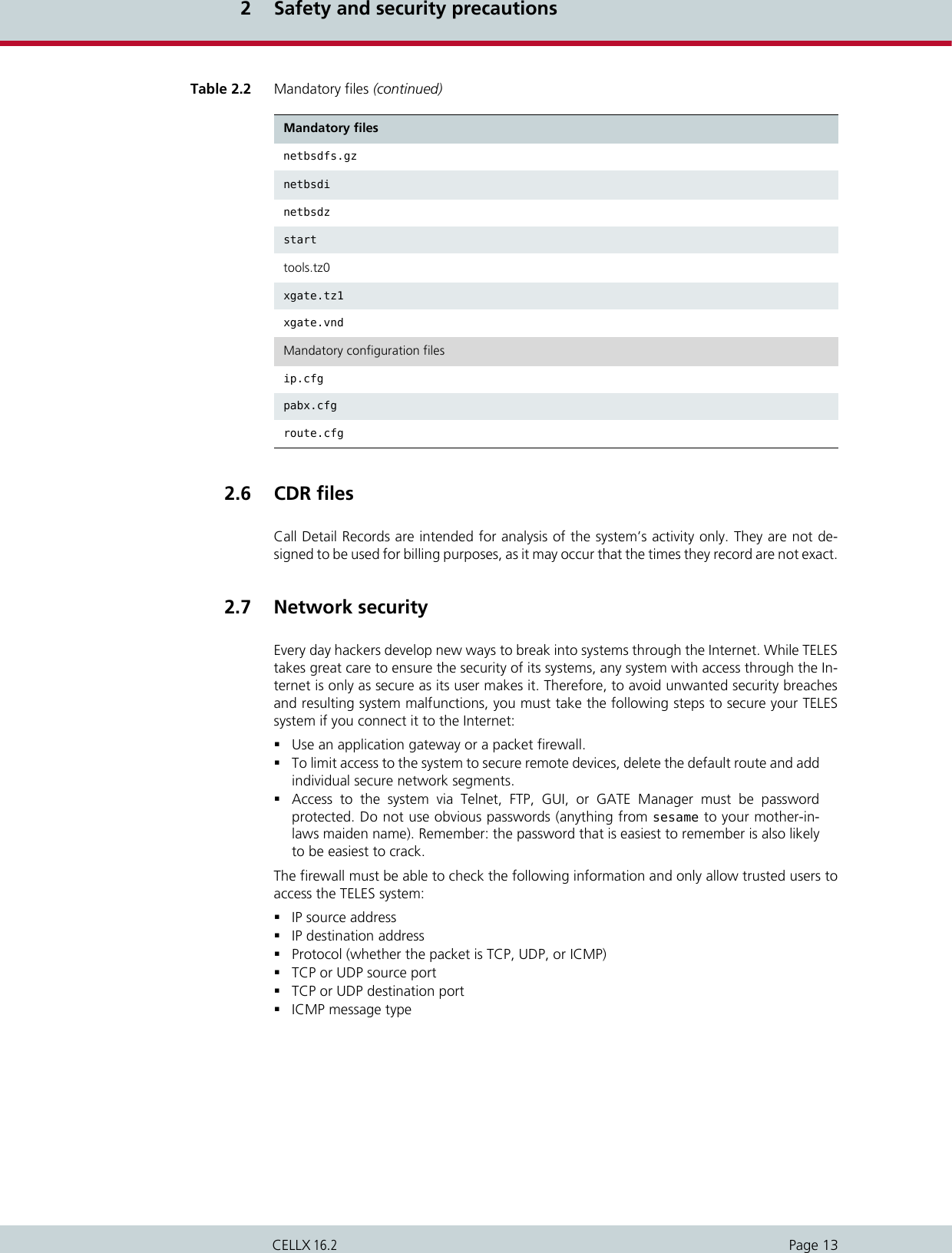
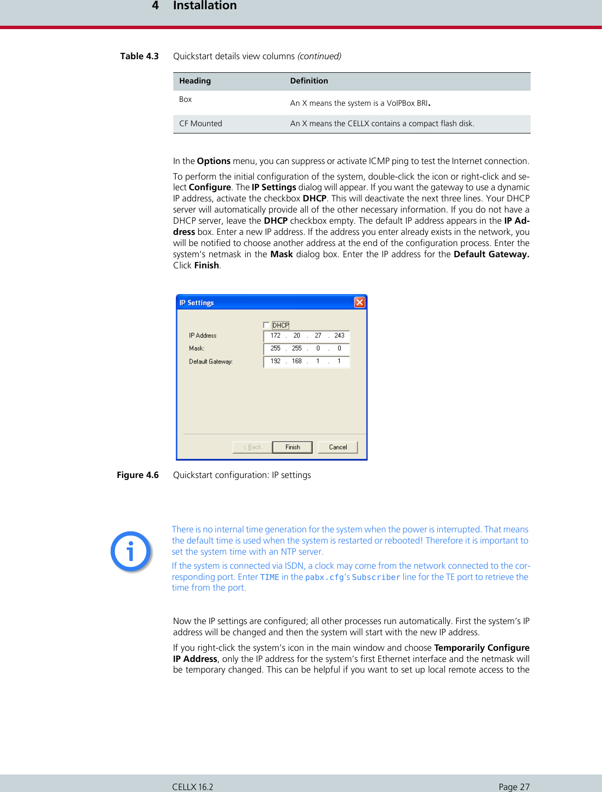
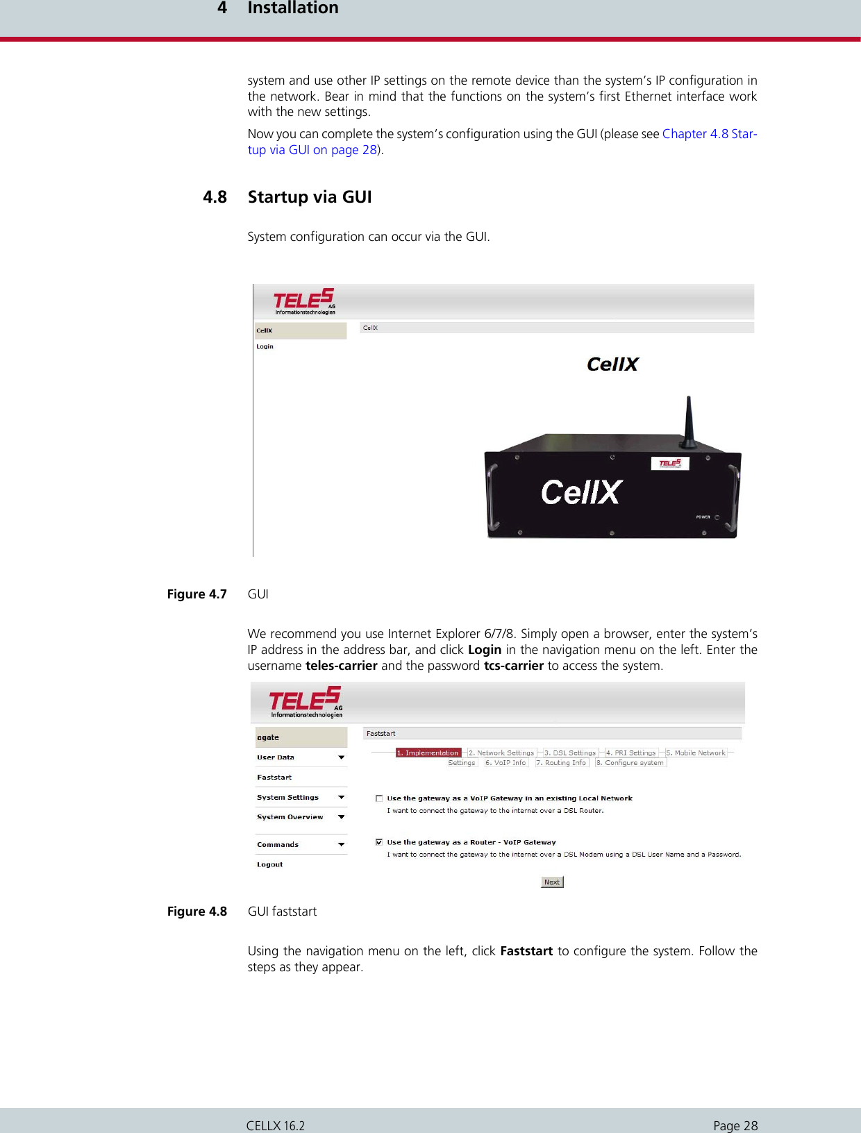
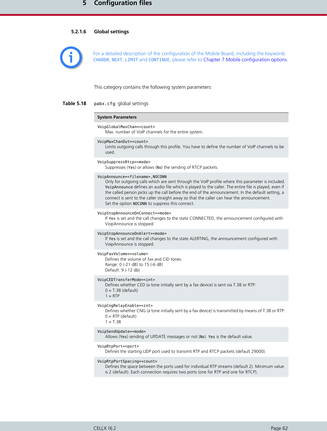
![4 InstallationPage 25CELLX 16.2In a SIM4 carrier, each SIM card corresponds with one mobile controller. In the pabx.cfgSubscriber line each SIM card always gets the index 1, as shown in the example below.4.5 Preparing for installationEach computer that is to communicate with the CELLX requires a network connection. DHCPcan be used to automatically assign an IP address and the netmask. If you don’t use DHCP,please have the following information for connection to your network available:IP address in the local network for the CELLX to be configuredNetmask for the CELLX to be configuredDefault gateway for CELLX to be configured4.6 Hardware connectionConnect your computer with the local networkConnect the CELLX with the local networkIf you choose to connect the CELLX to ISDN, use the ISDN connection cables includedin the package contents to connect the CELLX with your PBX and/or the PSTN accordingto the required port configuration.Connect the CELLX to the power supply.4.7 Startup with QuickstartQuickstart is an application that helps you to configure the IP settings of your CELLX quicklyand conveniently without changing any network settings on your computer. Quickstart can be installed on any of the following operating systems:Windows 2000Windows XPWindows VistaWindows 7If you are using any of these operating systems, please follow the instructions in this chapter.4.7.1 Installing QuickstartMake sure the GATE Manager is not running on your computer. To install Quickstart on yourcomputer, insert the CD and select Quickstart from the menu. Example 4.3 SIM card assignment to mobile controllers (SIM4 carrier)Subscriber00=TRANSPARENT GSM[0000,00000,+491770610000,1,1,1,SIM4] ALARMSubscriber01=TRANSPARENT GSM[0000,00000,+491770610000,1,1,1,SIM4] ALARMSubscriber02=TRANSPARENT GSM[0000,26202,+491770610000,1,1,1,SIM4] ALARM Subscriber03=TRANSPARENT GSM[0000,00000,+491770610000,1,1,1,SIM4] ALARMBear in mind that the preconfigured CELLX’s default IP address is 192.168.1.2. If it is already being used in your local network, you must run Quickstart without a connection to your local network. This can occur using a back-to-back Ethernet connection from your computer to the CELLX. If the desired IP address for the CELLX is not in your network, you must assign your computer a temporary IP address from this range.ii](https://usermanual.wiki/Teles-Informationstechnologien/CDMA32VOIPUS/User-Guide-1599912-Page-27.png)
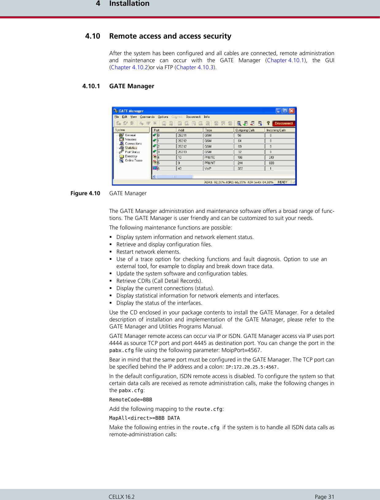
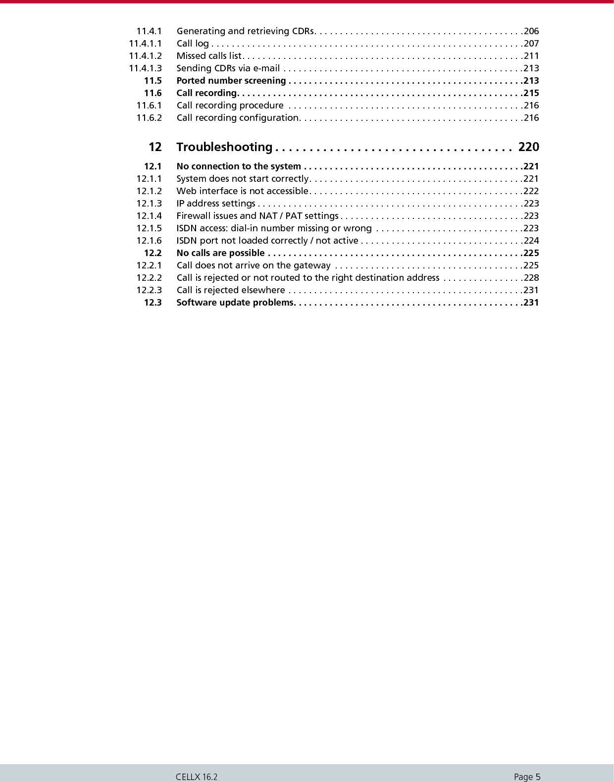
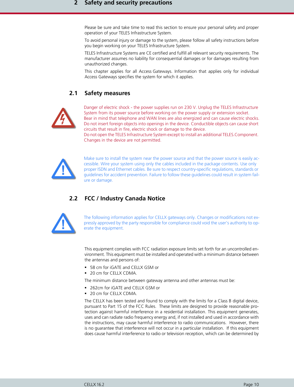
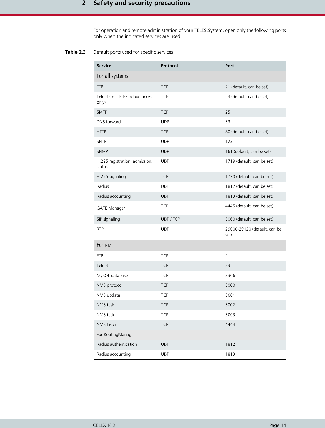
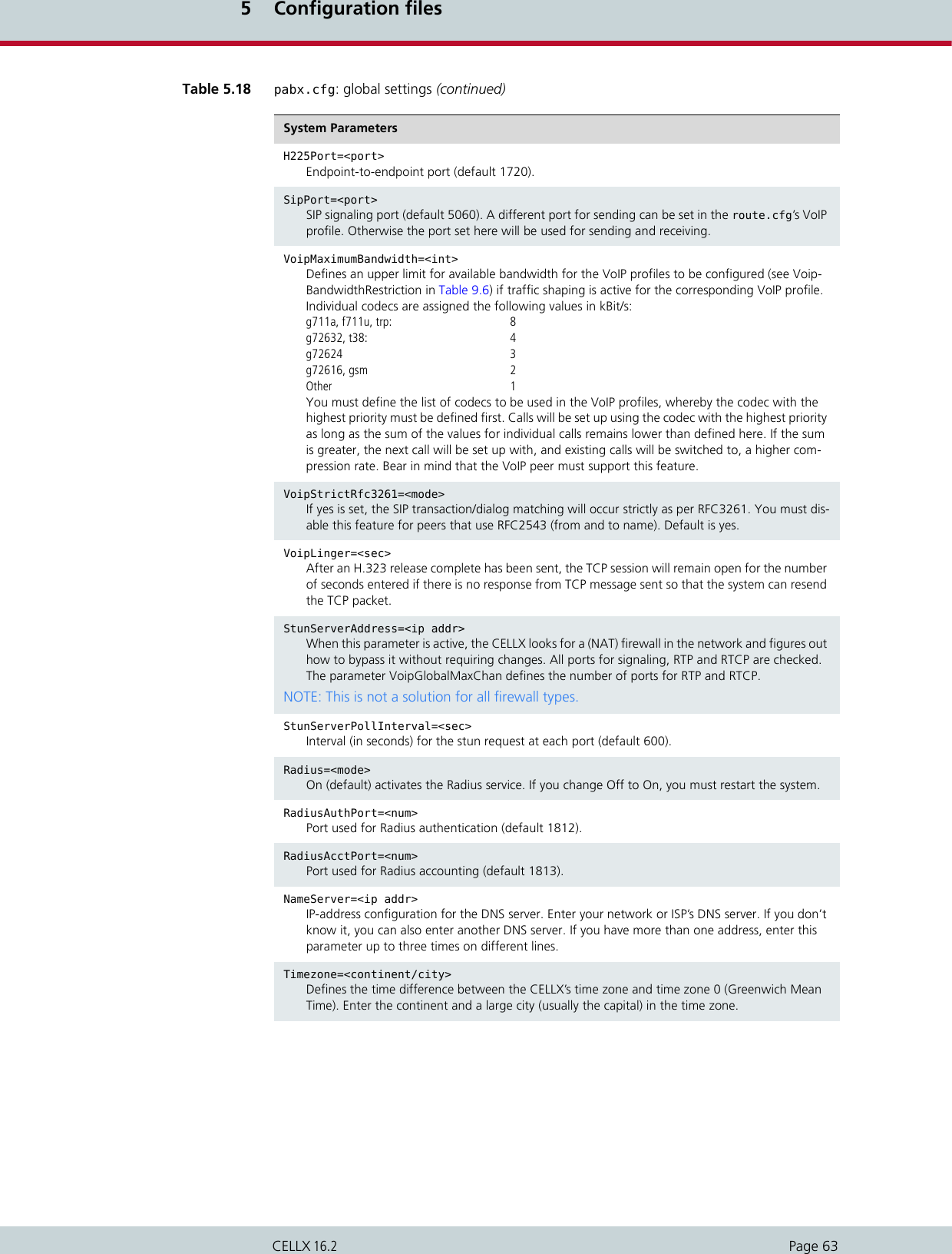
![4 InstallationPage 32CELLX 16.2MapAll?=BBB DATA 4.10.2 Graphical user interface (GUI)Remote access can occur via the GUI. Even users with little experience can easily configurestandard system settings with this interface. Simply open a browser and enter the system’s IPaddress in the address bar. Figure 4.11 GUIThe following administrative levels apply:Carrier mode (full access)User: teles-carrierPassword: tcs-carrierAll configuration pages can be accessed in this mode.Example 4.4 Carrier mode (full access)[httpd]PwdUser=k24X0sdc.uMcMPwdAdmin=k2UMj19qtovzIPwdCarrier=k2jryo6Xd5vN6Never copy these entries from one system to another, as the encryption is unique for each sys-tem.ii](https://usermanual.wiki/Teles-Informationstechnologien/CDMA32VOIPUS/User-Guide-1599912-Page-34.png)

![5 Configuration filesPage 37CELLX 16.2This chapter describes the basic setup and the most commonly used entries for the configu-ration files. Configuration of CELLXs is managed in the following three files: The default configuration with the IP address 192.168.1.2 is active when the files are not onthe system. You can configure the files using GATE Manager or via FTP (user teles, passwordtcs-ag). If you use the GUI to make configuration changes, the files will be adjusted automat-ically.Make sure you secure the system with new passwords following configuration and rememberto memorize the passwords! These configuration files contain all system-specific settings and are used when the systemstarts. Comments included in these files must begin with a semicolon. They do not need tobe at the beginning of a line. Configuration files must end with an empty line.Please save a backup of the files pabx.cfg and route.cfg before starting configuration.The configuration files follow these conventions: Individual files are divided into sections.These sections always begin with a line entry in square brackets. The basic required sectionsare in these files: Table 5.1 Configuration filesFile Functionip.cfg This file is for the basic configuration of the Ethernet interfaces.pabx.cfg This file is for system-specific and port-specific settings.route.cfg This file is for call-routing entries.Changing configuration data and/or SIM card positions may lead to malfunctions and/or mis-routing, as well as possible consequential damage. All changes are made at own risk. TELES is not liable for any possible damage out of or in relation with such changes. Please do there-fore thoroughly check any changes you or a third party have made to your configuration.iiiiTable 5.2 Required configuration file sectionsSection File Function[System] pabx.cfgroute.cfgip.cfgThis section contains the sys-tem’s basic settings. [Night<num>]EXAMPLE: [Night1][Night2]pabx.cfgroute.cfgThis section contains time de-pendent entries that only apply for limited times.[emac0] ip.cfg This section contains the IP configuration for the first Ethernet interface.](https://usermanual.wiki/Teles-Informationstechnologien/CDMA32VOIPUS/User-Guide-1599912-Page-39.png)
![5 Configuration filesPage 38CELLX 16.25.1 Configuration file ip.cfgThe basic settings for the two Ethernet interfaces are entered here. One interface usually suf-fices. The second interface can be used for special requirements, for example as a hub port,DSL router or vLAN interface. Generally, these settings are entered once and then left un-changed. This file contains the following sections, which must appear in the order given: 5.1.1 System section configurationThe [System] section contains entries that define the default gateway and/or special routingentries. To define the standard gateway, use the following entry to set the IP address:DefaultGw=<ip addr>Table 5.3 Sections in the ip.cfg fileSection Function[System] (required) This section contains entries that define the default gateway and/or special routing entries.[emac0] (required)[emac1] (optional)The Ethernet Media Access Controller section(s) define the physical Ethernet interface(s).[nat] (optional) This section includes settings for Network Address Translation.[bridge0] (optional) These section(s) contain settings for the second Ethernet con-troller in bridge mode.[pppoe<x>] (optional) These sections contain settings for direct connection between the system and the DSLAM when the PPPoE protocol is used. <x> can be 0 or 1.[firewall] (optional) This section contains settings for activating the system’s fire-wall.[altqd] (optional) This section enables prioritization of VoIP packets in the CELLX through an IP network using bandwidth control.[dhcpd] (optional) This sections contains a list of parameters and settings for the DHCP server in the system. It is divided into global settings for the server and parameters for the DHCP subnet.[xppp<x>] (optional) This section contains settings for point-to-point dial-up setup via ISDN.[vlan<x>] (optional) These section(s) contain settings for the virtual networks. <x> can be anything from 0 to 9.Example 5.1 System section configuration 1[System]DefaultGw=192.168.1.254](https://usermanual.wiki/Teles-Informationstechnologien/CDMA32VOIPUS/User-Guide-1599912-Page-40.png)
![5 Configuration filesPage 39CELLX 16.2If you must route specific net ranges to gateways other than what is defined in the defaultroute, make the following entries in the [System] section:Route=<target range> -netmask <ip mask> <ip gateway>If only certain routes apply, leave the line DefaultGw empty.5.1.2 Ethernet interface configurationThe system includes two Ethernet interfaces (emac0 and emac1). Only the first is active in thedefault configuration. Therefore, make sure you plug the cable into the right controller. Thesecond Ethernet interface can be configured as needed.The following settings are possible for the sections [emac0] (matched to the first Ethernetcontroller) and [emac1] (matched to the second Ethernet controller):IpAddress=<ip addr>/<netmask> The IP address is entered in decimal notation, followed by a slash (/) and the netmask in bitnotation.The following entry is used to allocate an IP address via DHCP: IpAddress=dhcpThe following entry is used in the [emac1] section if operation of the system occurs in bridgemode.IpAddress=up5.1.3 GUI settingsThe following parameter is used to change the GUI port in the section [httpd] (default 80):GuiPort=<num>Bear in mind that the passwords for different access levels are not set here. The encryptedpasswords are stored here and can only be changed via GUI (see Chapter 4.10.2 on page 32).Example 5.2 System section configuration 2[System]DefaultGw=192.168.1.254Route=10.0.0.0 -netmask 255.0.0.0 192.168.1.1Example 5.3 Ethernet interface configurationIpAddress=192.168.1.2/24Example 5.4 GUI settings[httpd]GuiPort=80PwdUser=k24X0sdc.uMcMPwdAdmin=k2UMj19qtovzIPwdCarrier=k2jryo6Xd5vN6](https://usermanual.wiki/Teles-Informationstechnologien/CDMA32VOIPUS/User-Guide-1599912-Page-41.png)
![5 Configuration filesPage 40CELLX 16.25.1.4 Bridge configurationA bridge can connect two networks with each other. A bridge works like a hub, forwardingtraffic from one interface to another. Multicast and broadcast packets are always forwardedto all interfaces that are part of the bridge. This can occur on the Ethernet or VLAN level:BrConfig=add <interface-x> add <interface-y> upActivating another Ethernet interface in this way is useful, for example, when the Ethernetswitch does not have any more ports available for connection of the system. You can simplyunplug a cable and plug it into the system’s second Ethernet interface.5.1.5 NAT configurationThe NAT (Network Address Translation) module translates IP addresses from the local net-work to an IP address or range on a public interface. All rules are defined in the [nat] section: Example 5.5 Bridge configuration[bridge0]BrConfig=add emac0 add emac1 upTable 5.4 NAT configuration map=<interface> <local network address/mask> -> <public network address/mask> <op-tional entries>This parameter maps the IP address in the local network to the IP address in the public network.<interface> Defines the translated interface or protocol:emac1 The system’s second Ethernet interfacepppoe0 Protocol used for DSL connectionsxppp<0> Protocol used for ISDN and CDMA dial-up connections<local network address/mask> The IP address is entered in decimal notation, followed by a slash (/) and the netmask in bit notation. The entire local net-work range is configured.<public network address/mask> Defines the public network range, with network address and mask (usually exactly one address), into which the local IP ad-dresses are to be translated. The IP address is entered in dec-imal notation, followed by a slash (/) and the netmask in bit notation.<optional entries> Special rules can be defined for some services or protocols. The system can serve as a proxy for FTP: proxy port ftp ftp/tcpSpecial ports for the public address(es) can be assigned for the protocols TCP and UDP. The range is defined by the start and end ports:portmap tcp/udp <start port>:<end port>If no optional entry is defined, all other addresses will be translated without special rules.rdr=<interface> <public network address/mask> port <port> -> <local network address/mask> port <port_number> <protocol>This parameter sends packets from one port and IP address to another.](https://usermanual.wiki/Teles-Informationstechnologien/CDMA32VOIPUS/User-Guide-1599912-Page-42.png)
![5 Configuration filesPage 41CELLX 16.2The following NAT settings are for a system in which PPPoE (DSL) is used toward the Internet.The local network range 192.168.1.0 Class C is translated with the following rules:The proxy mode is used for FTP. All other TCP and UDP packets are mapped to the external ports 40000 to 60000. There are no special rules for any other services.Incoming requests to port 80 and 443 in the public IP address 192.168.1.100 areredirected to ports 80 and 443 in the local IP address 192.168.1.100.5.1.6 PPPoE configurationThe protocol Point-to-Point over Ethernet is used for DSL communication with the DSLAM.That means the system can connect directly with a DSL modem. All necessary information for setup of the PPPoE connection is defined in the [pppoe<x>] sec-tion. That means username, password and authentication protocol are set here. The Ethernetinterface is emac1 and the gateway can also be defined. The parameter PppoeIf defines thephysical Ethernet interface used (always emac1). The settings are entered as follows: Bear inmind that configuration of the firewall, the NAT module and prioritization of the VoIP packetsmust be considered when routing voice and data through the DSL line.<interface> Defines the translated interface or protocol:emac1 The system’s second Ethernet interfacepppoe0 Protocol used for DSL connectionsProtocol used for ISDN and CDMA dial-up connections<public network address/mask> Defines the public network range, with network address and mask (usually exactly one address), into which the local IP ad-dresses are to be translated. The IP address is entered in dec-imal notation, followed by a slash (/) and the netmask in bit notation.<port> Defines the port number.<local network address/mask> The IP address is entered in decimal notation, followed by a slash (/) and the netmask in bit notation. The entire local net-work range is configured.<protocol> Defines the protocol. tcp and udp are possible.watch=<interface 1> <interface 2> ... <interface n>Enter all interfaces that you have configured. If an interface is activated, the NAT table is resetted to ensure correct IP address translation.Table 5.4 NAT configuration (continued)Example 5.6 NAT configuration[nat]map=emac1 192.168.1.0/24 -> 0/32 proxy port ftp ftp/tcpmap=emac1 192.168.1.0/24 -> 0/32 portmap tcp/udp 40000:60000map=emac1 192.168.1.0/24 -> 0/32rdr=emac1 0/0 port 80 -> 192.168.1.100 port 80 tcprdr=emac1 0/0 port 443 -> 192.168.1.100 port 443 tcp](https://usermanual.wiki/Teles-Informationstechnologien/CDMA32VOIPUS/User-Guide-1599912-Page-43.png)
![5 Configuration filesPage 42CELLX 16.2The following entry will create the interface pppoe0, with the username user and the pass-word pwd. The PAP authentication protocol is used. The default route occurs via DSL.5.1.7 Firewall settingsIn the following example, only port 4445 allows incoming connections from the IP address192.168.1.10. All others will be blocked.Example 5.7 PPPoE configuration[pppoe0]PppoeIf=emac1 User=userPwd=pwdAuthProto=papRoute=0.0.0.0The firewall settings provide options for limiting or denying access to and from the system. If you do not configure this section, the firewall is inactive and access is unlimited. Make sure you configure the firewall rules carefully. The rules are processed from top to bottom. If you use the option quick, you will break the sequence. We recomend that you put the most re-strictive rule at the end of the configuration.iiExample 5.8 Firewall settings 1[firewall]fw=pass in quick on emac0 proto tcp from 192.168.1.10/32 to any porteq 4445 flags S keepstate keep frags fw=block in log quick on emac0 allTable 5.5 Settings in the [firewall] section of the ip.cfg [firewall]fw=<mode> <direction> <list><mode> Two modes are possible for permitting or deny-ing access:pass permit accessblock deny access<direction> Possible directions are in and out:in external to internalout internal to external<list> All other entries specify the other settings for the corresponding firewall rules and are optional. The order in the line is as listed below:log Records non-matching packets.](https://usermanual.wiki/Teles-Informationstechnologien/CDMA32VOIPUS/User-Guide-1599912-Page-44.png)
![5 Configuration filesPage 43CELLX 16.2quickAllows short-cut rules in order to speed up the filter or override later rules. If a packet matches a filter rule that is marked as quick, this rule will be the last rule checked, allowing a short-circuit path to avoid processing later rules for this packet. If this option is missing, the rule is taken to be a "fall-through rule, meaning that the result of the match (block/pass) is saved and that pro-cessing will continue to see if there are any more matches.on <interface>The firewall rule is used only for the defined interface (for example emac0, pppoe0).from <networkaddress/mask>to <networkaddress/mask>from defines the source IP-address range for incoming packets. to defines the target IP-address range for outgoing packets. The IP address appears in decimal notation, followed by a slash (/) and the netmask in bit notation. any stands for all IP addresses (example: to any).NOTE: If you use the rule pass in/out in combination with the option from <ip> to <ip>, you must specify a protocol number with proto and a port number. If you not specify the port, the system may not be reachable. EXAMPLE:fw=pass in quick on pppoe0 proto tcp from any to any port eq 4445proto <protocol>defines the protocol, for which the rule is valid (example: proto tcp, proto udp, proto icmp).port eq <num><num> defines the port as number (example: port eq 4445).keep stateEnsures that the firewall checks packets from the beginning to the end of a session. This is nec-essary, as the firewall cannot process when a session begins or ends.flags SOnly syn. packets are accepted and recorded in the state table. In conjunction with keep state, packets from sessions that have been inactive will also be routed. The advantage of this entry is that random packets will not be accepted.keep fragsFragmented packets are also routed.Table 5.5 Settings in the [firewall] section of the ip.cfg (continued)[firewall]fw=<mode> <direction> <list>](https://usermanual.wiki/Teles-Informationstechnologien/CDMA32VOIPUS/User-Guide-1599912-Page-45.png)
![5 Configuration filesPage 44CELLX 16.25.1.8 Bandwidth controlIn many implementation scenarios, the CELLX in router mode (for example as DSL router)sends voice and data traffic through a connection with limited bandwidth. This can lead tolost voice packets that arrive too late to be used in the voice stream. To avoid lost packets,this QOS setting prioritizes packet transmission. You must set the priority for voice signalingand for the voice packets. That means you must prioritize SIP/H.323, RTP and RTCP. You willfind the ports used in Table 5.14, in the following entries:H225PortSipPortVoipRtp PortVoipRtpPortSpacingDifferent ports are used for RTP and RTCP, depending on the configuration.The parameter VoipRtpPort shows the first RTP port used. The corresponding RTCP port is thenext one up. The parameter VoipRtpPortSpacing shows the next RTP port (RTP port + portspacing).Example 5.9 Firewall settings 2[firewall]; loopbackfw=pass in quick on emac0 allfw=pass out quick on emac0 all; traffic to outgoingfw=pass out quick on pppoe0 proto tcp all flags S keep state keep fragsfw=pass out quick on pppoe0 proto udp all keep state keep fragsfw=pass out quick on pppoe0 proto icmp all keep state keep frags; incoming trafficfw=pass in quick on pppoe0 proto tcp from 10.4.0.0/16 to any port eq 21 flags S keep state keep fragsfw=pass in quick on pppoe0 proto tcp from 10.4.0.0/16 to any port eq 23 flags S keep state keep fragsfw=pass in quick on pppoe0 proto tcp from 10.4.0.0/16 to any port eq 4445 keep state ; icmp trafficfw=pass in quick on pppoe0 proto icmp all keep state; other will be blockedfw=block in log quick on pppoe0 allfw=block out log quick on pppoe0 allTable 5.6 Settings in the [altqd] section of the ip.cfg Interface=<interface> bandwidth <bw> priqDefines the interface for which the rule applies.<interface> Sets the interface for which prioritization applies (e.e. pppoe0).<bw> Sets the bandwidth that is available on the inter-face in Kbit/s (for example 256K).priq Priority qeueing. A higher priority class is always served first.classPrio=<interface> <class> root priority <prio>](https://usermanual.wiki/Teles-Informationstechnologien/CDMA32VOIPUS/User-Guide-1599912-Page-46.png)
![5 Configuration filesPage 45CELLX 16.2In the following example, prioritization is set for a thirty-channel VoIP connection. The SIP sig-naling port 5060 and the RTP/RTCP ports 29000 to 29059 are prioritized at level 7. All otherservices are set at level 0.Defines the priority of the filter entries.<class> Two types can be set:realtime_class (VoIP packets)regular_class (data packets)<prio> Enter a value between 0 and 15. The higher the value (for example 15), the higher the priority.Filter=<interface> <class> <values>Defines the individual rules for the class.<values> The individual values are divided into the follow-ing entries. A 0 can be entered as a wildcard, in which case all values are possible:<dest_addr> (can be followed by netmask <mask>)<dest_port><src_addr> (can be followed by netmask <mask>)<src_port><protocol tos value>:6 for TCP17 for UDPTable 5.6 Settings in the [altqd] section of the ip.cfg (continued)Interface=<interface> bandwidth <bw> priqExample 5.10 Bandwidth control[altqd]interface pppoe0 bandwidth 512K priqclass priq pppoe0 realtime_class root priority 7 filter pppoe0 realtime_class 0 5060 0 0 0 filter pppoe0 realtime_class 0 0 0 5060 0 filter pppoe0 realtime_class 0 29000 0 0 17 filter pppoe0 realtime_class 0 0 0 29000 17 filter pppoe0 realtime_class 0 29001 0 0 17 filter pppoe0 realtime_class 0 0 0 29001 17 .... filter pppoe0 realtime_class 0 29058 0 0 17 filter pppoe0 realtime_class 0 0 0 29058 17 filter pppoe0 realtime_class 0 29059 0 0 17 filter pppoe0 realtime_class 0 0 0 29059 17 class priq pppoe0 regular_class root priority 0 default](https://usermanual.wiki/Teles-Informationstechnologien/CDMA32VOIPUS/User-Guide-1599912-Page-47.png)
![5 Configuration filesPage 46CELLX 16.25.1.9 DHCP server settingsThe DHCP (Dynamic Host Configuration Protocol) server provides a mechanism for allocationof IP addresses to client hosts. The [dhcpd] section contains a list of parameters and settingsfor the DHCP server in the system. It is divided into global settings for the server and param-eters for the DHCP subnet.Table 5.7 Settings in the [dhcpd] section of the ip.cfg [dhcpd]; Global dhcpd parametersallow unknown-clients;All DHCP queries are accepted and the configured settings are transmitted to the clients.ddns-update-style none;Deactivates dynamic update of the domain name system as per RFC 2136.; Parameters for the Subnetsubnet <network address> netmask <mask for network range> {<list>}In <list> you can enter any of the following specific network settings activated by the DHCP server. Each oprion must begin in a new line and end with a semicolon (;).range <start IP address> <end IP address>;The DHCP network range is defined by the first and last address in the range. Client assignment begins with the last address.option broadcast-address <IP address>;Defines the broadcast address for the clients in the subnet.option domain-name "<string>";Defines the domain name used in the network.option domain-name-servers <IP address>;Defines the DNS-server address to be assigned (as per RFC 1035)All of the following optional entries defining server addresses are also transmitted as per RFC 1035. Separate multiple addresses per server with a comma: … <IP address>, <IP address>; (this also applies for all other optional entries with IP addresses).option netbios-name-servers <IP address>Defines the WINS-server address to be assigned.option ntp-servers <ip address>;Defines the NTP-server address to be assigned.option time-servers <ip address>;Defines the time-server address to be assigned (RFC 868).option routers <IP address>;Defines the router address to be assigned.option subnet-mask <net mask>;Defines the netmask to be assigned (as per RFC 950).option tftp-server-name "<link>";Defines the TFTP server name (option 66), as per RFC 2132.EXAMPLE: option tftp-server-name "http://192.168.0.9";](https://usermanual.wiki/Teles-Informationstechnologien/CDMA32VOIPUS/User-Guide-1599912-Page-48.png)
![5 Configuration filesPage 47CELLX 16.25.1.10 DNSmasq settingsDnsmasq is an easy to configure DNS forwarder. It is designed to provide DNS to a small net-work.Example 5.11 DHCP server settings[dhcpd]; Global dhcp parametersallow unknown-clients;ddns-update-style none;; Parameter for the Subnetsubnet 192.168.1.0 netmask 255.255.255.0 { range 192.168.1.3 192.168.1.20; option broadcast-address 192.168.1.255; option domain-name "company.de"; option domain-name-servers 192.168.1.100; option routers 192.168.1.2; option subnet-mask 255.255.255.0;}Table 5.8 Settings in the [dnsmasq] section of the ip.cfg [dnsmasq]bogus-privBogus private reverse lookups. All reverse lookups for private IP ranges (ie 192.168.x.x, etc) which are not found in /etc/hosts or the DHCP leases file are answered with "no such domain" rather than being forwarded upstream.filterwin2kLater versions of windows make periodic DNS requests which don't get sensible answers from the public DNS and can cause problems by triggering dial-on-demand links. This flag turns on an op-tion to filter such requests. The requests blocked are for records of types SOA and SRV, and type ANY where the requested name has underscores, to catch LDAP requests.user=<username>Specify the userid to which dnsmasq will change after startup. Dnsmasq must normally be started as root, but it will drop root privileges after startup by changing id to another user. Normally this user is "nobody" but that can be over-ridden with this switch.cache-size=<cachesize>Set the size of dnsmasq's cache. The default is 150 names. Setting the cache size to zero disables caching.clear-on-reloadWhenever /etc/resolv.conf is re-read, clear the DNS cache. This is useful when new nameservers may have different data than that held in cache.Example 5.12 DNSmasq settingsbogus-privfilterwin2kuser=telescache-size=150cler-on-reload](https://usermanual.wiki/Teles-Informationstechnologien/CDMA32VOIPUS/User-Guide-1599912-Page-49.png)
![5 Configuration filesPage 48CELLX 16.25.1.11 PPP configuration for mobile and ISDN dial-upThe point-to-point protocol is used for dial-up connections via GPRS/3G or CMDA, or via ISDNlines. The system can set up an mobile Internet connection for the companies’ local users oran ISDN data link between subsidiaries of the company.The mobile internet access can be used as regular internet access for small companies or asan internet back up solution.The ISDN dial-up can be used to transmit VoIP calls.The advantages of VoIP over ISDN can be seen especially in corporate implementation. Forexample, it is useful when a very high number of connections occurs between subsidiaries andone subsidiary does not have a broadband Internet connection. An ISDN B-channel can beconnected to the Internet and up to six voice calls can occur simultaniously over one ISDN line.All necessary information for setup of the PPP connection is defined in the section [xp-pp<num>].Table 5.9 Settings in the [xppp] section of the ip.cfg [xppp<num>]Dad=<num>Enter the dial-up number. Only digits can be defined here. Any required special characters (* or #) can be set in the mapping entry.User=<username>Enter a username.Pwd=<password>Enter a password.Route=<ip-addr>Enter the target IP address range, for example 0.0.0.0 (default route).AuthProto=<protocol>Enter chap or pap for the protocol used for authentication.AutoUp=<int>Defines if the PPP interface is activated automatically after system start. The following values are possible:0 = No automatic PPP activation (default)1 = Automatic PPP activationIdleTO=<sec>Enter the number of seconds without traffic before the interface tears down the connection.MTU=<int>Maximum Transfer Unit. We recommend the following default values:1500 for ISDN dial-up and 120 for CDMA dial-up.Rfc1662=<val>Framing to be used:0 for ISDN or 1 for CDMALcpTO=<msec>Allows you to change the value of the LCP timeout. The timeout-value must be specified in milli-seconds (default 1000).StartDelay=<sec>Time in seconds the system will wait to start the ppp process.](https://usermanual.wiki/Teles-Informationstechnologien/CDMA32VOIPUS/User-Guide-1599912-Page-50.png)
![5 Configuration filesPage 49CELLX 16.2Make sure you configure the firewall and NAT options accordingly.5.1.12 VLAN configurationA VLAN (Virtual Local Area Network) is a virtual LAN within a physical network. Each VLAN isassigned a unique number (VLAN ID) and defined in the [vlan<x>] section with Tag: value between 1 and 4095Priority: value between 0 and 7 (0 is lowest and 7 is the highest priority)[vlan0]IfConfig=vlan <tag>,<priority> vlanif <interface>The following entry will create the interface vlan1, with VLAN tag 10 and priority 7, on theEthernet interface emac0. Following this configuration, IP addresses (and/or other protocols)can be assigned to the vlan1 interface.DNS=<bitmask>Enter here to which of the carrier’s DNS server the gateway shall send the DNS request. The fol-lowing values are possible:1 = primary DNS server2 = secondary DNS server3 = both serversOwnIP=<IP address>A temporay IP address assigned to the interface (such as 0.0.0.0). This address is valid until an IP address has been assigned to the interface by the carrier. Not needed for the xppp0 interface.PeerIP=<IP address>The IP address that is configured for the peer (such as 0.0.0.1). Not needed for the xxxp0 interface, each other interface has to have a different peer IP address.Example 5.13 PPP configuration for ISDN and CDMA dial-up[xppp0]Dad=12345User=userPwd=pwdRoute=0.0.0.0AuthProto=chapIdleTO=60MTU=1500Rfc1662=0LcpTO=500StartDelay=10AutoUp=1Table 5.9 Settings in the [xppp] section of the ip.cfg (continued)[xppp<num>]Example 5.14 VLAN configuration[vlan1]IfConfig=vlan 10,7 vlanif emac0IpAddress=192.168.199.1](https://usermanual.wiki/Teles-Informationstechnologien/CDMA32VOIPUS/User-Guide-1599912-Page-51.png)
![5 Configuration filesPage 50CELLX 16.25.1.13 Examples5.1.13.1 Default configurationIn the following example, the system’s IP address is 192.168.1.1, the netmask is255.255.255.0, and the standard gateway is 192.168.1.254.5.1.13.2 Active ethernet bridgeIn the following example a two-port Ethernet bridge is configured. The system’s IP address is192.168.1.1, the netmask is 255.255.255.0, and the standard gateway is 192.168.1.254,The emac1 interface is active and both Ethernet interfaces are set to bridge mode in the[bridge0] section.Example 5.15 Default configuration[System]DefaultGw=192.168.1.254[emac0]IpAddress=192.168.1.1/24Example 5.16 Active ethernet bridge[System]DefaultGw=192.168.1.254[emac0]IpAddress=192.168.1.1/24[emac1]IpAddress=up[bridge0]BrConfig=add emac0 add emac1 up](https://usermanual.wiki/Teles-Informationstechnologien/CDMA32VOIPUS/User-Guide-1599912-Page-52.png)
![5 Configuration filesPage 51CELLX 16.25.1.13.3 Integrated DSL-router scenario for VoIPIn the following example, the system is connected to the local IP network through emac0. TheDSL modem is connected to the emac1 interface, which enables the system to connect direct-ly to the Internet without an additional router when the connection is used only for VoIP data.A DHCP server is used for dynamic IP-address allocation.Example 5.17 Integrated DSL-router scenario for VoIP traffic with an active DHCP server and firewall[System][emac0]IpAddress=192.168.0.2/24[emac1]IpAddress=up[pppoe0]PppoeIf=emac1 User=usertelekomPwd=pwdAuthProto=chapRoute=default[nat]map=pppoe0 192.168.0.0/24 -> 0/32 proxy port ftp ftp/tcpmap=pppoe0 192.168.0.0/24 -> 0/32 portmap tcp/udp 40000:60000map=pppoe0 192.168.0.0/24 -> 0/32[firewall]; loopbackfw=pass in quick on emac0 allfw=pass out quick on emac0 all; traffic to outgoingfw=pass out quick on pppoe0 proto tcp all flags S keep state keep fragsfw=pass out quick on pppoe0 proto udp all keep state keep fragsfw=pass out quick on pppoe0 proto icmp all keep state keep frags; incoming trafficfw=pass in quick on pppoe0 proto tcp from 10.4.0.0/16 to any port eq 21 flags S keep state keep fragsfw=pass in quick on pppoe0 proto tcp from 10.4.0.0/16 to any port eq 23 flags S keep state keep fragsfw=pass in quick on pppoe0 proto tcp from 10.4.0.0/16 to any port eq 4445 keep state ; icmp trafficfw=pass in quick on pppoe0 proto icmp all keep state; other will be blockedfw=block in log quick on pppoe0 allfw=block out log quick on pppoe0 all[dhcpd]; Global dhcp parametersallow unknown-clients;ddns-update-style none;; Parameter for the Subnetsubnet 192.168.1.0 netmask 255.255.255.0 { range 192.168.1.3 192.168.1.20; option broadcast-address 192.168.1.255; option domain-name "company.de"; option domain-name-servers 192.168.1.100; option routers 192.168.1.2; option subnet-mask 255.255.255.0;](https://usermanual.wiki/Teles-Informationstechnologien/CDMA32VOIPUS/User-Guide-1599912-Page-53.png)
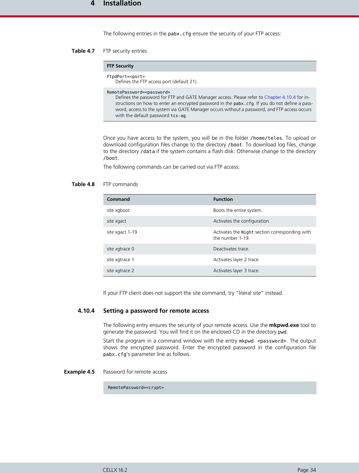
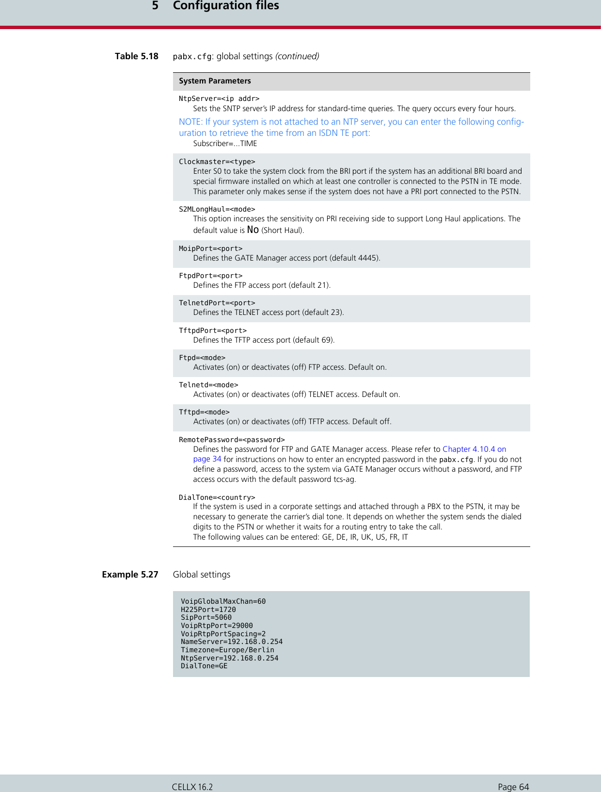
![5 Configuration filesPage 52CELLX 16.25.1.13.4 VLAN scenarioIn the following example, the system is connected to the IP backbone through emac0. OneComputer is connected to the emac1 interface. You can separate voice and data traffic withtwo different VLANs (vlan0 with tag 10 for voice, vlan1 with tag 11 for data). All traffic com-ing from emac1 will be sent to vlan1. Voice and data will not be mixed.5.2 Configuration file pabx.cfgThe pabx.cfg file contains system-specific settings and the port configuration. It is dividedinto the [System] and [Night<num>] sections.5.2.1 System settingsThe [System] section is divided into several categories to ensure clarity. Global settingsLog filesControllersSubscribersIP configurationThe following subchapters contain a detailed description of these categories.5.2.1.1 Global SettingsThe entry in this category is responsible for the life-line (bypass) functionality of the PRI port’srelay when the system is on. When the system is off, both PRI ports are connected to eachother, which means that it provides a transparent connection between the PBX and the PSTNif the system is installed between the PBX and the PSTN. When the system is on, all routingalgorithms are active.Bypass=ON/OFFON: PRI relay is on (system controls both PRI ports).Example 5.18 VLAN scenario[System][emac0]IpAddress=192.168.1.12/16[emac1]IpAddress=up[vlan0]IfConfig=vlan 10,7 vlanif emac0IpAddress=10.0.1.2/24[vlan1]IfConfig=vlan 11,1 vlanif emac0IpAddress=172.16.4.5/16[bridge0]BrConfig=add vlan1 add emac1 up](https://usermanual.wiki/Teles-Informationstechnologien/CDMA32VOIPUS/User-Guide-1599912-Page-54.png)
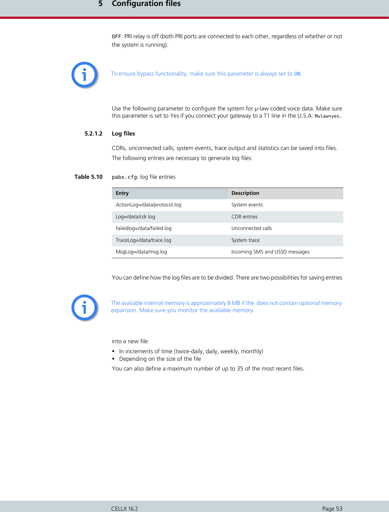
![5 Configuration filesPage 54CELLX 16.2A dash (-) appears in place of information that is to be ignored.In the following entry, the files cdr.log and failed.log are renamed every day or when thefile reaches 180kB, whichever comes first. Up to 7 CDR files will be saved on the system. Ifthe file size reaches 180kB on one day, the second file will have the same date. Only the run-ning number will be increased.In the following entry, the file protocol.log is renamed every day or when the file reaches 60kB. Up to 21 failed files will be saved on the system.In the following entry, the file trace.log is renamed every day when the file has reached600kB. Up to seven log files will be saved on the system.Table 5.11 pabx.cfg: log parameters Log=/data/<file.log> <saved> <size> <number><file> The name of the log file is generated as follows: [file]yymmdd[0-9|A-Z].log.<saved> Refers to the frequency with which the file is saved. The following op-tions are possible:halfdaily Every day at 11:59 and 23:59daily Every day at 23:59weekly Sunday at 23:59monthly The last day of the month at 23:59<size> Regardless of the value entered in <saved>, the file will be saved when the <file size> has been reached (in kB).NOTE: We recommend a file size of a multiple of 60kB.<number> Refers to the number of files that will be saved in the system (between 5 and 35) before the first file is overwritten. This setting is useful not only for limited file size, but also for files that store events. Normally size can be limited for these files, for example 5 files of 1MB each. If the fifth file is full, the first one will automatically be overwritten.Example 5.19 Log files renamed 1Log=/data/cdr.log daily 180 7failedlog=/data/failed.log daily 180 7Example 5.20 Log files renamed 2ActionLog=/data/protocol.log daily 60 21Example 5.21 Log files renamed 3TraceLog=/data/trace.log daily 600 7](https://usermanual.wiki/Teles-Informationstechnologien/CDMA32VOIPUS/User-Guide-1599912-Page-56.png)
![5 Configuration filesPage 57CELLX 16.2The individual ports are defined with the following parameters.Table 5.14 pabx.cfg: controller parameters Controller<port>=<address> <type> <mode> <line_type> ADR:<hardware address> IRQ:<in-terrupt> UNIT:<unit> VALUE:<value><port> Defines the running (physical) port number.<address> Defines the configured (virtual) port address. In the default configuration, PRI TE ports are 9 and PRI NT ports are 10. VoIP ports are 40.<type> Defines the connection type:TES2M PRI external (terminal endpoint)NTS2M PRI internal (network termination)VOIP VoIP moduleGSM GSM portCDMA CDMA portUMTS UMTS portTE BRI external (if you change from NT to TE or vice versa, you must change the DIP switches for the respective port on the 4BRI Board)NT BRI internal DTMF virtual controller for activating DTMF tone detection<mode> Defines the protocol variation for PRI and BRI lines:DSS1 CASR2 (only for PRI lines)<line_type> Switches CRC4 mode for PRI lines on or off:CRC4 CRC4 onDF double frame: CRC4 offAdditional entry for T1 only:T1 US Defines this controller as T1. Bear in mind that if one con-troller is defined as T1, all controllers must be thus de-fined. If you configure T1, you must also enter CHMAX[23] in the corresponding Subscriber lines.T1 EXAMPLE:MULAW=YesController00=20 TES2M DSS1 T1 US Controller01=21 NTS2M DSS1 T1 US...Subscriber00 = TRANSPARENT ROUTER CHMAX[23]Subscriber01 = TRANSPARENT ROUTER CHMAX[23]ADR:<hardware ad-dress>(Optional) Defines the hardware address used for the first controller on an additional Mobile Board. These entries are preconfigured and cannot be changed.IRQ:<interrupt> (Optional) Defines the interrupt used for the first controller on an addi-tional Mobile Board. These entries are preconfigured and cannot be changed.](https://usermanual.wiki/Teles-Informationstechnologien/CDMA32VOIPUS/User-Guide-1599912-Page-59.png)
![5 Configuration filesPage 59CELLX 16.25.2.1.5 SubscribersVarious functions for individual interfaces (ISDN or VOIP) are defined in each controller’s Sub-scriber line. The order of the subscriber lines is the same as the order of the controller lines(see Chapter 5.2.1.4 on page 56). Most changes become active following a restart. If it suf-fices to activate the configuration, this is noted in the parameter description.Additional parameters for mobile controllers are described in Table 5.16 and Table 5.17. Theparameters listed in Table 5.16 are required for mobile controllers and those listed in Table5.17 are optional, depending on the implementation scenario.Table 5.15 pabx.cfg: subscriber parameters Subscriber<port>=<list><port> Refers to the running (physical) port number.The <list> variable may contain one or more of the following keywords:DEFAULT The standard configuration will be used. No other parameters in this table are set.TRANSPARENT Only the number is sent as caller ID (without the virtual port address). Activate configuration suffices to activate changes. If TRANSPARENT is not set, the address of the incoming port is added to the A party number as a prefix.CASR2[<name>] Activates the profile defined in the corresponding [CASR2] section.ALARM Activates the monitoring mode for the respective port. If a relevant error occurs at the port, the error is written in the protocol.log file. Depending on the configuration, a remote connection to the number defined for AlarmCallback is established and/or an SNMP trap is gen-erated. Activate configuration suffices to activate changes.SWITCH Changes internal port handling. In the default configuration, the VoIP controller is set to NT. You can use this parameter to change it from NT to TE. Restart the system to activate the changes.CHMAX[xx] Defines the number of channels per controller, for example 5 for the virtual DTMF controller. A maximum of five concurrent channels are possible for DTMF detection.CHSTART[xx]CHSTART[xx,<mode>]Defines the channel where the search for availabe B-channels for out-going calls starts. Three optional modes are possible for the mode of search: CYC, LIN, INV:CYC A round-robin search for the next free B channel oc-curs. The first call receives the first B channel, the second call the second B channel and so on. When the respective B channel is occupied, then the next one is selected. LIN The search for the next free B channel occurs linear-ly. The search always begins at the specified B chan-nel. When that B channel is busy, the next one is selected until a free B channel is found.INV The search for the next free B channel occurs in-versely and always begins at the specified B channel. When that B channel is busy, the previous one is se-lected.DTMF[<sec>,/<dir>/<file>]Please refer to Chapter 11.2.1 Announcements.](https://usermanual.wiki/Teles-Informationstechnologien/CDMA32VOIPUS/User-Guide-1599912-Page-61.png)
![5 Configuration filesPage 60CELLX 16.2Required mobile parametersSpecific settings for each mobile interface appear in square brackets behind the keywordsGSM, UMTS or CDMA. These parameters are separated with a comma. Example 5.26 Subscriber settings 1Subscriber00=TRANSPARENT ROUTER ALARMSubscriber01=TRANSPARENT ROUTER ALARMSubscriber02=TRANSPARENT ROUTER SWITCH CHMAX[16] ALARMTable 5.16 Required mobile parameters in pabx.cfg Subscriber<port>=<type>[<pin>,<lain>,<SMSC>,<sim>,<loudGSM>,<loudPCM>,SIM<x>,...]<port> Refers to the running (physical) port number.<type> Enter GSM, CDMA or UMTS depending on your hardware configuration.<pin> Defines the SIM card’s PIN. The PIN is always four digits. If no PIN is defined for a SIM card, the PIN 0000 must be used.NOTE: An error message appears in the protocol.log file when a PIN is incorrectly configured.<lain> Defines the LAIN (Local Area Identification Number) – the mobile network to be used. The LAIN consists of the MCC (Mobile Country Code) and the MNC (Mobile Network Code). Setting this parameter prevents roaming into another mobile network. If the LAIN is set at 00000, roaming will not be prevented. The LAIN configuration prevents accidental logon of the SIM card with another net-work and the use of false SIM cards.<SMSC> Defines the SMS center’s access number. The number must always begin with + and the country code.<SIM> Defines the SIM card to be used. You can enter the values 1, 2, 3, 4, 5, 6 (op-tional when using the 24 SIM card carrier). Default 1. Do not change the de-fault entry if your gateway is equipped with SIM4 carriers . Activate configuration suffices to activate changes.NOTE: Please see the example following Table 5.17 for information on numbering SIM cards.<loudGSM> Defines the volume level for the mobile line. The values 0 to 3 are possible. 0 is loudest and 3 is the least loud.Activating echo cancellation (for GSM modules only):Depending on the base station (BTS) one of three algorithms will work for this feature. The algorithms must be tested during activation to determine which one fits the base station type.The following values are added to the volume setting:- 16 -> algorithm 1 - 32 -> algorithm 3 - 48 -> algorithm 6 EXAMPLE 1: If the volume level is set at 1, and algorithm 1 is used for echo can-cellation, the configuration for <loudGSM> is 17:Subscriber00=… GSM[0000,00000,+000000,1,17,1,SIM4] …EXAMPLE 2: If the volume level is set at 2, and algorithm 6 is used for echo can-cellation, the configuration for <loudGSM> is 50:Subscriber00=… GSM[0000,00000,+000000,1,50,1,SIM4] …](https://usermanual.wiki/Teles-Informationstechnologien/CDMA32VOIPUS/User-Guide-1599912-Page-62.png)
![5 Configuration filesPage 61CELLX 16.2Optional mobile parametersIn addition to the usual parameters, you can enter the following optional mobile parameters.Separate each parameter with a comma. <loudPCM> Defines the volume level to the fixed network. The values 0 to 7 are possible. 7 is loudest and 0 is the least loud.SIM4 Indicates that the gateway is equipped with SIM4 carriers. Table 5.16 Required mobile parameters in pabx.cfg (continued)Subscriber<port>=<type>[<pin>,<lain>,<SMSC>,<sim>,<loudGSM>,<loudPCM>,SIM<x>,...]Table 5.17 Optional mobile parameters in pabx.cfg Parameter DescriptionBAND(<int>) Defines the GSM frequency band and (<int>) can have the following values:1 = Mono-band mode 850MHz (Q24CL001 modules only)2 = Mono-band mode 900MHz (Q24CL001 modules only)3 = Mono-band mode 1800MHz (Q24CL001 modules only)4 = Mono-band mode 1900MHz (Q24CL001 modules only)5 = Dual-band mode 850/1900MHz (Q24CL001 and GE864-QUAD modules)6 = Dual-band mode 900/1800MHz (Q24CL001 and GE864-QUAD modules)7 = Dual-band mode 900/1900MHz (Q24CL001 and GE864-QUAD modules)8 = Dual-band mode 850/1800MHz (GE864-QUAD modules only)After changing the band settings, you must restart the system to activate the changes.NOTE: The BAND parameter can only be used with quad-band GSM module-type Q24CL001. These quad-band GSM modules are avail-able as of hardware revision 1.61 (May, 2007). There is no default band setting! If there is no BAND configuration in the pabx.cfg when the system is started, the last band stored on the module will be used. This can cause the system to attempt to register the SIM with the wrong GSM band.BNDS<int> For UMTS Boards with module type UC864-G only:Selects the UMTS or GSM or auto network0 = auto (default)1 = GSM2 = UMTS BNDU(<int>) For UMTS Boards with module type UC864-G only:Configures BAND selection in the UMTS network0 = 850/1900/2100 MHz (default)1 = 850 MHz2 = 1900 MHz3 = 2100 MHz](https://usermanual.wiki/Teles-Informationstechnologien/CDMA32VOIPUS/User-Guide-1599912-Page-63.png)
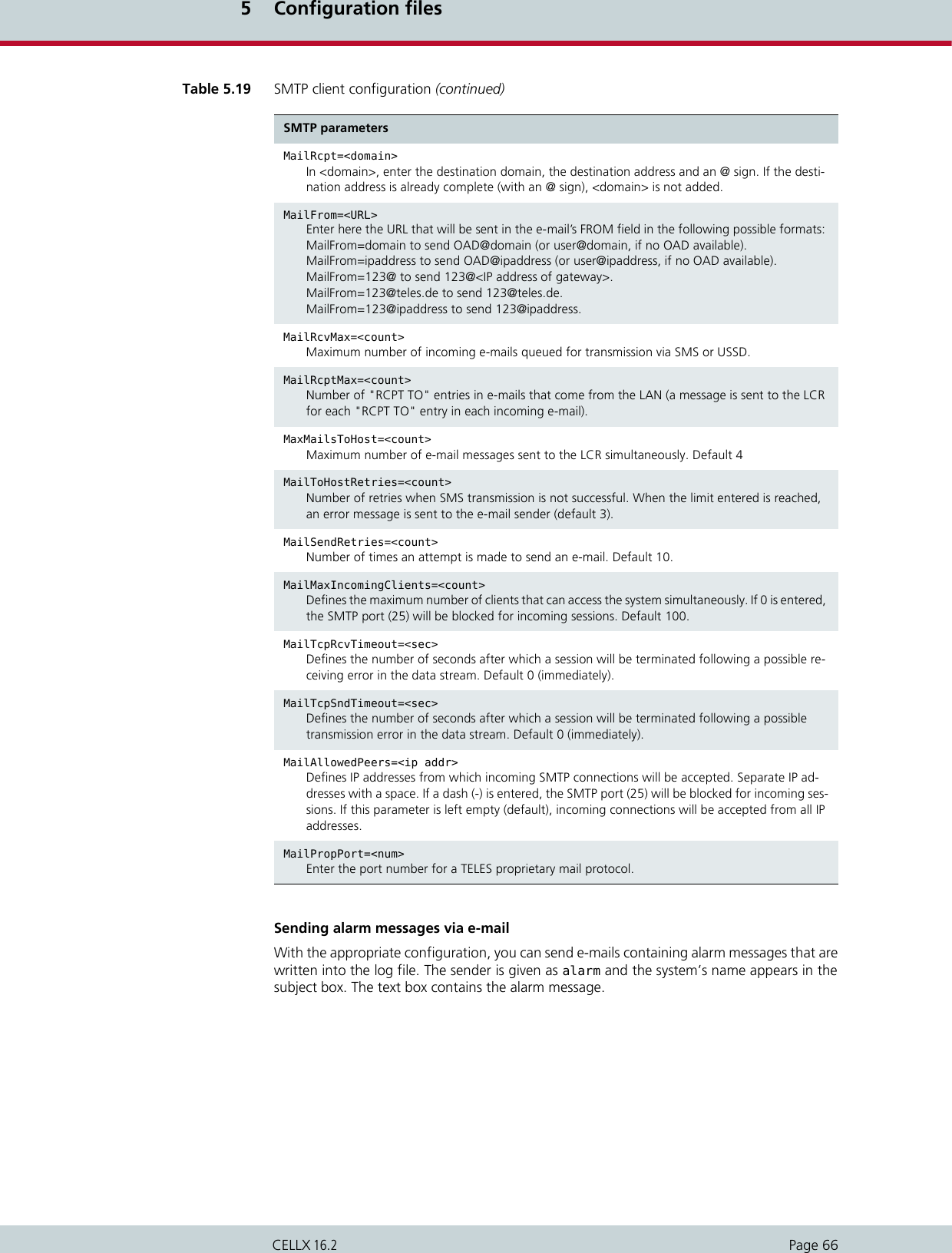
![5 Configuration filesPage 65CELLX 16.25.2.2 SMTP-client configurationThe following entries in the pabx.cfg’s [Mail] section are used to send e-mail messages fromthe CELLX. The connection to the SMTP server can be used to send CDR files, incoming SMSto an e-mail account or alarm messages.The following features are possible:Sending SMS via e-mailReceiving SMS in an e-mail, SMS or in a fileSending and receiving USSD text messagesDisplaying incoming calls via e-mailSetting up connections using e-mailSending automatic SMS for unconnected callsSending CDRs via e-mailSending alarm messages via e-mailThere is no internal time generation for the system when the power is interrupted. That means the default time is used when the system is restarted or rebooted! Therefore it is important to set the system time with an NTP server. Alternatively, if the system is connected via BRI or PRI, a clock may come from the network connected to the corresponding port. Enter TIME in the pabx.cfg’s subscriber line of the TE port and then activate the configuration to activate this clock.iiYou must restart the system after making changes to activate the settings.iiTable 5.19 SMTP client configuration SMTP parametersSmtpServer=<ip addr>In <ip addr>, enter the IP address of the destination SMTP server that is to receive the e-mail messages. MailUserIn=<username>Enter a username for incoming e-mail authentication.MailUserOut=<username>Enter a username for outgoing e-mail authentication.MailPwdIn=<password>Enter a password for incoming e-mail authentication.MailPwdOut=<password>Enter a password for outgoing e-mail authentication.MailPortIn=<num>Enter a TCP port for incoming email (default 25).MailPortOut=<num>Enter a TCP port for outgoing email (default 25).MailAuthEncr=<type>Enter an encryption method for e-mail authentication (default base64).](https://usermanual.wiki/Teles-Informationstechnologien/CDMA32VOIPUS/User-Guide-1599912-Page-67.png)
![5 Configuration filesPage 67CELLX 16.2The following entry in the configuration file activates this function.5.2.3 Number portability settingsThe [NumberPortability] section includes the parameters necessary for communication withthe database server. For a description of the functionality and configuration of this feature,please see Chapter 11.5 Ported number screeningExample 5.28 Sending alarm messages via e-mai...ActionLog=/data/protocol.log daily 1000 5 @<e-mail account>...You must restart the system after making changes to activate the settings.Table 5.20 Number portability settings Number portability parametersMNPQAddress=<ip addr>For iMNP or direct queries to Enquire: Enter the IP address to which the number portability query is to be sent.MNPQPort=<port>For iMNP or direct queries to Enquire: Enter the tcp port to which the number portability query is to be sent.MNPQAddress2=<ip addr>For iMNP or direct queries to Enquire: Enter the IP address to which the second number portability query is to be sent when ! appears in the mapping entry. A second database will then be queried, for example if the first one is not online.MNPQPort2=<port>For iMNP or direct queries to Enquire: Enter the tcp port to which the second number portability query is to be sent.MNPQSum=<mode>For iMNP: This parameter must be activated (Yes) if an iMNP is used.E2EMRSAddress=<ip addr>For direct queries to End2End: Enter the IP address to which the number portability query is to be sent.E2EMRSPort=<port>For direct queries to End2End: Enter the udp port to which the number portability query is to be sent. ii](https://usermanual.wiki/Teles-Informationstechnologien/CDMA32VOIPUS/User-Guide-1599912-Page-69.png)
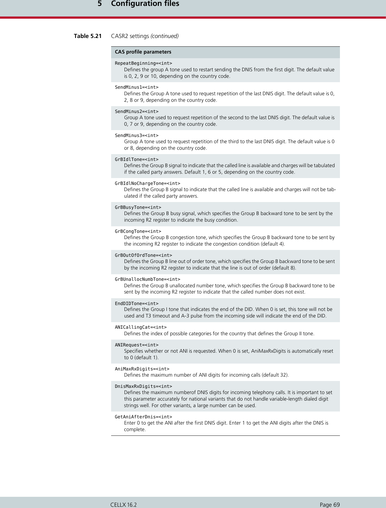
![5 Configuration filesPage 68CELLX 16.25.2.4 SNMP settingsThe Simple Network Management Protocol facilitates network management and monitoringof CELLX network devices and their functions. For a detailed description of SNMP configura-tion, please refer to Chapter 10.4 SNMP agent.5.2.5 Time-controlled configuration settingsThe [Night<num>] section is reserved for prospective time-controlled configuration changes.In the pabx.cfg file, the Night sections contain all of the system’s Subscriber entries.5.2.6 .CASR2 settingsIf you are working with Channel Associated Signaling, you must activate a CAS profile in therelevant Controller and Subscriber entries and define a profile for each Subscriber en-try in a separate [CASR2:<name>] section. Generally you will need to set only the country code 55 for Brazil. The default country codeis 0, which sets the ITU-T standard. You must restart the system after making changes to activate the settings.iiTable 5.21 CASR2 settings CAS profile parametersCountryCode=<num>Defines set of pre-configured R2 parameters according to the E.164 country code (for Brazil 55, etc.) When not defined or set at 0, the ITU-T standard set of parameters will be used. Default 0.CDbit=<int>Specifies the default setting of the C and D bits when the port transmits line signals. The default setting for C is 0 and for D is 1. Generally they will not need to be changed.Iabcd=<int>Specifies whether any of the A B C or D bits are inverted. Default is 0. Generally it will not need to be changed.BlockBeforeIdle=<int>Set to 1 when backward blocking is required (before going to idle) after the clear forward has been received (default 0).AnsTone=<int>Defines the Group A tone used to respond to incoming calls and switch to Group B tones (default 3).ANIReqCatTone=<int>Defines the group A tone used to request the calling-party category before the ANI digits. The default value is 5 or 6, depending on the country code.ANIReqAniTone=<int>Defines the Group A tone used to request the next ANI digit. The default value is 1, 2, 4, 5 or 9, depending on the country code.](https://usermanual.wiki/Teles-Informationstechnologien/CDMA32VOIPUS/User-Guide-1599912-Page-70.png)
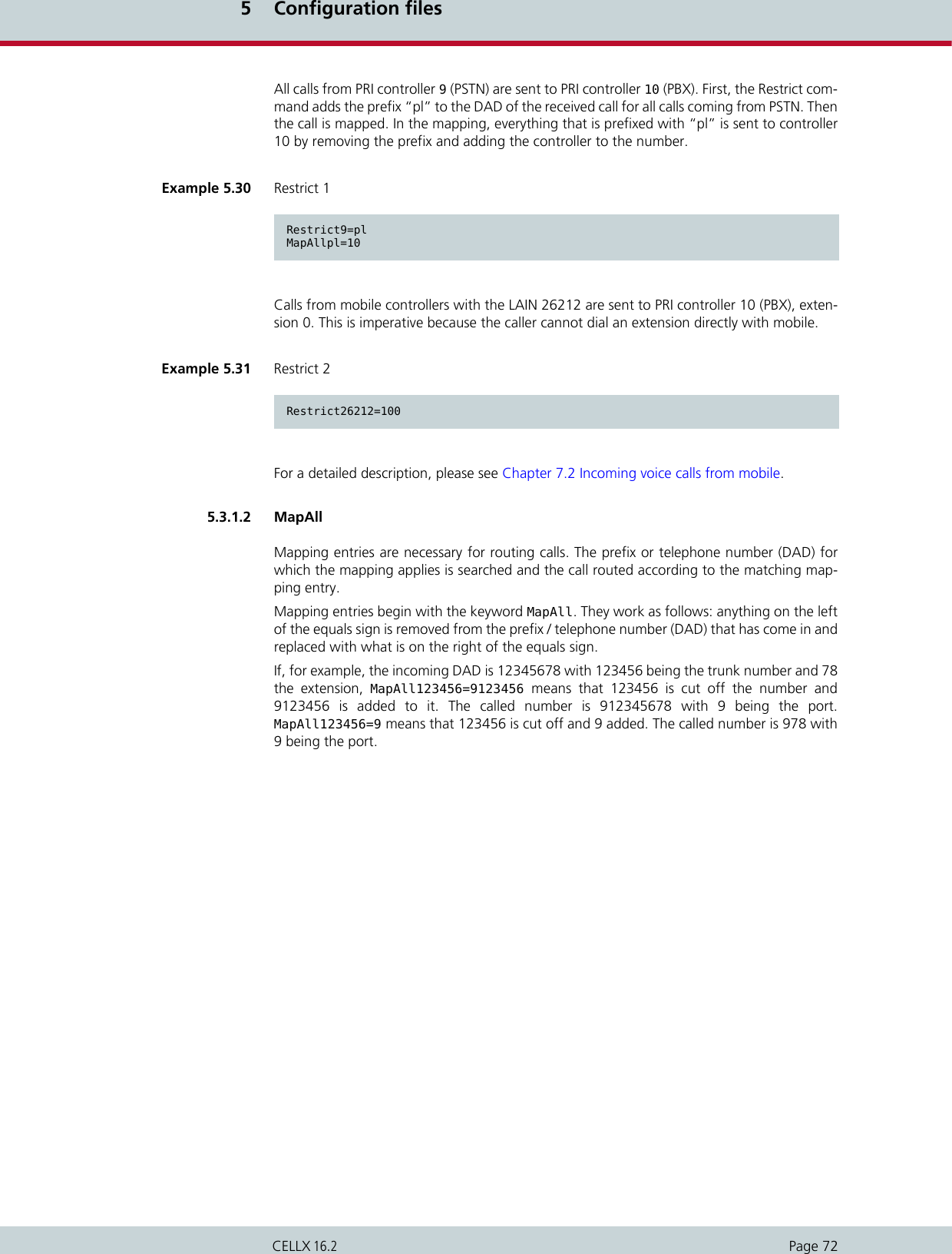
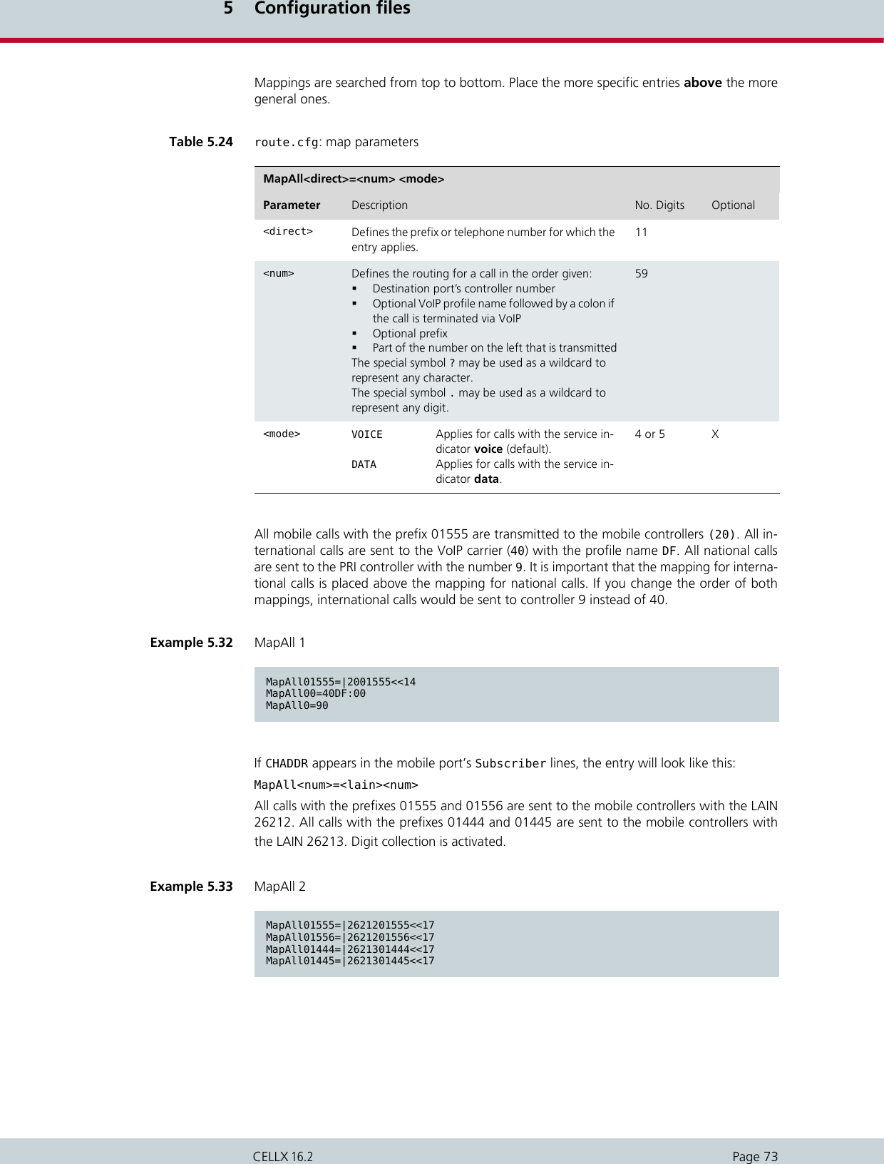
![5 Configuration filesPage 70CELLX 16.25.3 Configuration file route.cfgThe system’s routing information is saved in the route.cfg. The file contains the followingsections:5.3.1 Entries in the [System] sectionThe[System]section contains the following entries.5.3.1.1 RestrictRestrict entries are used to handle calls in a mapping based on the controller / controllergroup where the calls originate. A Restrict entry can be used, for instance, to route all callscoming from PSTN directly to the PBX. If no called party number (DAD) is transmitted, Re-strict can also be used to make the call mappable, for instance for calls coming from GSM.Example 5.29 CASR2 settingsController00=9 TES2M CASR2...Subscriber00 = TRANSPARENT ROUTER CASR2[BRAZIL1] ALARMSubscriber01 = TRANSPARENT ROUTER CASR2[BRAZIL2] ALARM...[CASR2:BRAZIL1]CountryCode=55[CASR2:BRAZIL2]CountryCode=55You must restart the system after making changes to activate the settings.iiTable 5.22 Sections in the route.cfg file Section Function[System] Contains all routing entries (MapAll, Restrict, Redirect) that are to be active when the default configuration is used.[Night<num>] Contains all routing entries (MapAll, Restrict, Redirect), and VoIP, gate-keeper and registrar profiles that are to be active with the defined time configuration. Bear in mind that you must also copy all routing and profile settings that may already appear in the das System section or in the indi-vidual profile sections, even if they do not change![VoIP:<name>] Contains all settings necessary for communication with the VoIP peer.[GateKeeper:<name>] Contains all settings for the gatekeeper. This profile is then assigned to the VoIP profiles.[Registrar:<name>] Contains all settings to register with the registrar.](https://usermanual.wiki/Teles-Informationstechnologien/CDMA32VOIPUS/User-Guide-1599912-Page-72.png)
![5 Configuration filesPage 71CELLX 16.2The Restrict parameter adds a prefix to a DAD before the DAD is mapped. Restrict pa-rameters are always handled before the MapAll parameters and always require a matchingMapAll parameter.The left side of the equals sign in the Restrict parameter contains the controller numberplus an optional trunk number or a specific calling number (OAD). The special symbol ? maybe used as a wildcard to represent any character. The right side contains the prefix that is tobe put in front of the DAD and an optional service indicator.In the route.cfg, the list of Restrict parameters is searched from bottom to top for amatching controller plus optional trunk number / OAD. Because the search is done bottomup, place the more specific Restrict entries below the more general ones. Once a matchhas been found, the DAD is prefixed with the contents of the <pl> variable. Then the call ismapped.Table 5.23 route.cfg: restrict parameters Restrict<ns>[R][T]=<pl> <sin>Parameter Description No. Digits Optional<ns> Contains the controller number plus an optional trunk number or a specific calling number (OAD). The special symbol ? may be used as a wildcard to represent any character. 59[R] For calls that are redirected with Redirect3, the original OAD can be changed again using RestrictR. Only in combination with service indica-tor 15.X[T] For calls that are redirected with Redirect2, the original OAD can be changed again using RestrictT. Only in combination with service indica-tor 15.X<pl> Stands for a virtual placeholder. The DAD is prefixed with the contents of this variable.59<sin> The service indicator variable sin restricts the com-mand to a service. Without a sin, the Restrict com-mand is valid for all services.Possible service indicator values are:00 All services01 Telephony02 Analog services03 X.21-services04 Telefax group 405 64 kbps videotext or TELES-specific SMS services06 TELES-specific USSD services07 Data transfer 64 kbps08 X.25-services09 Teletext 6410 Mixed mode15 Used internally for calling-party (OAD) manipulation.16 Video telephone2](https://usermanual.wiki/Teles-Informationstechnologien/CDMA32VOIPUS/User-Guide-1599912-Page-73.png)
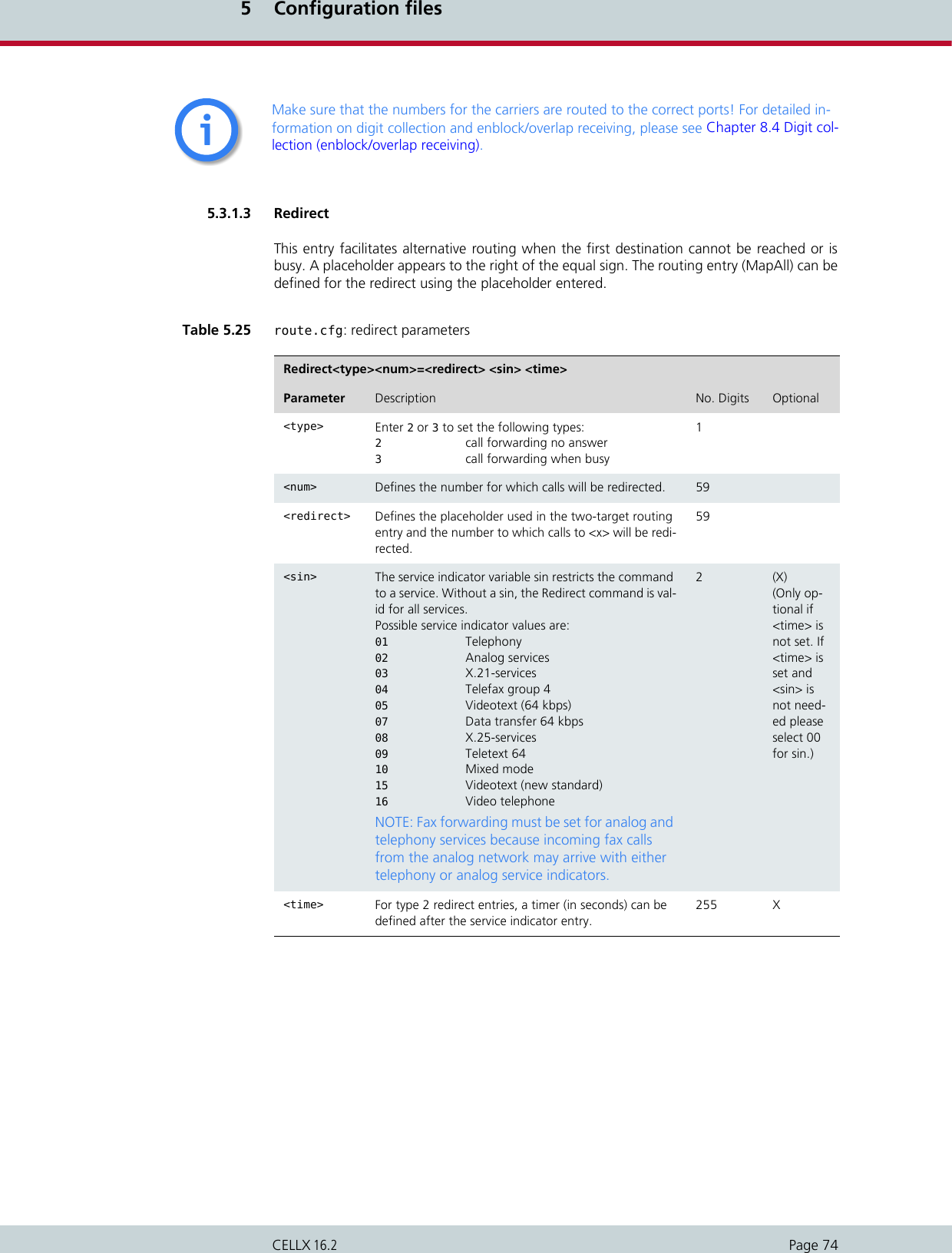
![5 Configuration filesPage 75CELLX 16.2In the following example, all mobile calls with the prefix 01555 are transmitted to the mobilecarrier with the LAIN 26212. Digit collection is activated. If the carrier cannot be reached oris busy, the redirect command activates the second target mapping with the placeholder Aand the call is automatically sent to PRI controller 9.In the following example, calls to 26212 that remain unanswered for 12 seconds and calls to26213 that remain unanswered for 20 seconds are redirected through the PRI port.Excluding busy calls or specific cause values from redirectDefines a hexadecimal cause value according to DSS1. When connections to the destinationare rejected because of the reason defined by the cause value, the CELLX sends a busy signalto the attached PBX. Alternative routing is not carried out.To avoid second-choice routings when the called-party number is busy, set the following pa-rameter in the first-choice port’s Subscriber line in the pabx.cfg:BUSY[<cause>]Defines a hexadecimal cause value according to DSS1. When connections to the destinationare rejected because of the reason defined by the cause value, the CELLX sends a busy signalto the attached PBX. Alternative routing is not carried out. You can also define a range ofconsecutive cause values: BUSY[<cause>,<cause>]An exclamation point (!) in front of a cause value means all cause values except the one listed.For example, BUSY[!95], means all cause values except 95 will be rejected with a busy signal.In the following example, all outgoing calls over controller 04 are rejected with the cause val-ue 91 when the called party is busy. Alternative routing is not carried out.5.3.1.4 Setting the time-controlled sectionsIf you use a time-configured route on the system, please see Chapter 5.2.1.3 for a definitionof individual configuration zones. The active route is configured in the route.cfg file.Example 5.34 Redirect 1MapAll01555=|2621201555<<17Redirect326212=AMapAllA=9Example 5.35 Redirect 2MapAll01555=|2621201555<<17MapAll01556=|2621301556<<17Redirect226212=A 01 12Redirect226213=A 01 20MapAllA=9Example 5.36 Called party is busySubscriber04=....BUSY[91]](https://usermanual.wiki/Teles-Informationstechnologien/CDMA32VOIPUS/User-Guide-1599912-Page-77.png)
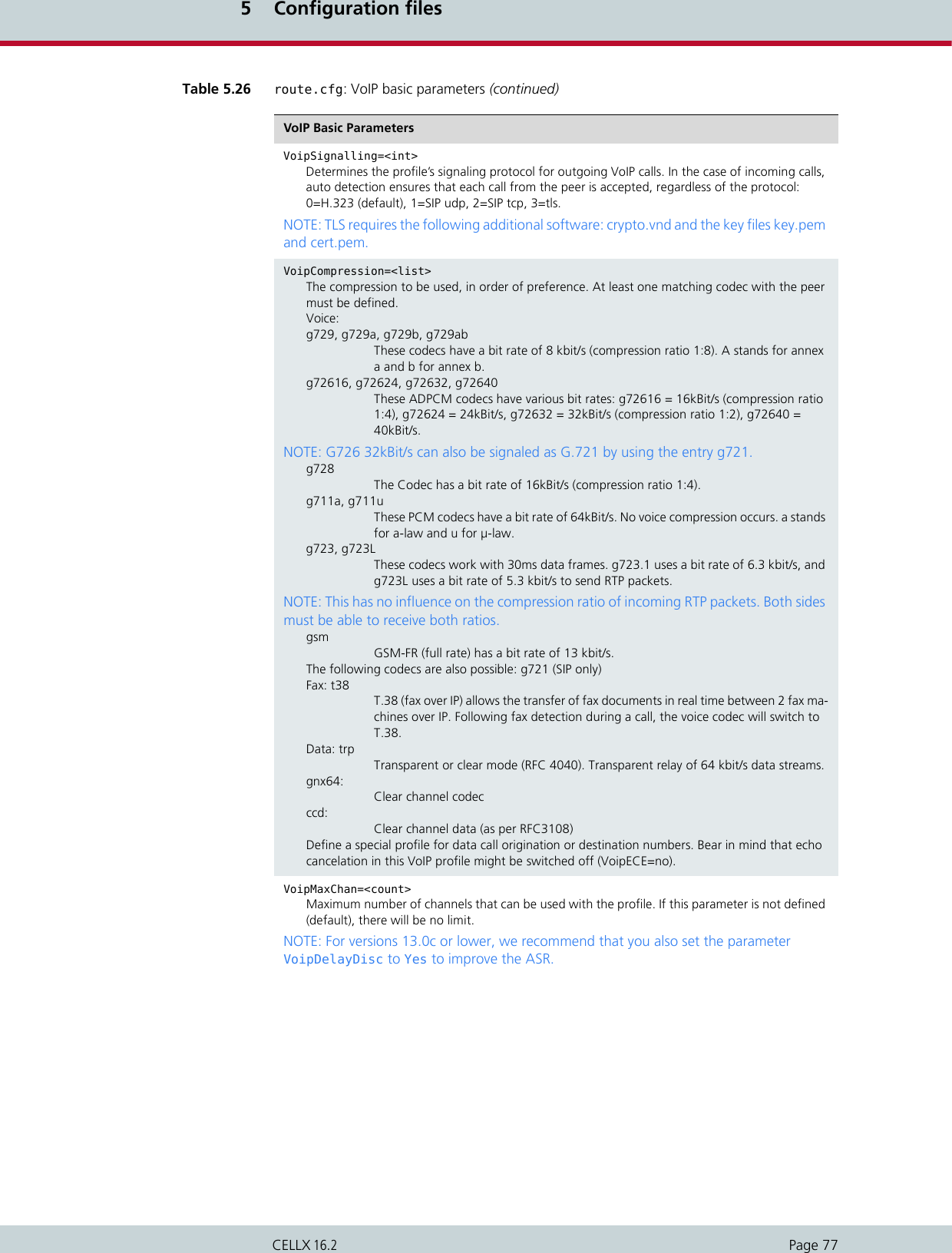
![5 Configuration filesPage 76CELLX 16.2The following example contains three sections ([System], [Night1] and [Night2]), in which theroute changes. All international calls are sent to the VoIP carrier DF in the default configura-tion. Digit collection is actived. In the time span for [Night1], these international calls are rout-ed to VoIP carrier Ni, and in the time span for [Night2] they are routed through the PRIcontroller to the carrier with the prefix 010xx. National calls are always sent to VoIP carrier DFand local calls are routed to the outside line.5.3.2 VoIP profilesThis section includes all of the most important parameters for communication with the VoIPpeer.Basic parametersExample 5.37 Setting the time-controlled sections[System]MapAll00=|40DF:00<<24MapAll0=|40DF:0<<24MapAll?=9?[Night1]MapAll00=|40Ni:00<<24MapAll0=|40DF:0<<24MapAll?=9?[Night2]MapAll00=9010xx00MapAll0=|40DF:0<<24MapAll?=9?Any defined Night configurations must be set in the files pabx.cfg and route.cfg. If there are no changes in these sections, you must copy them from the System section. The complete Subscriber section must appear in the Night section of the pabx.cfg (see Chapter 5.2.5 on page 68). The active route must appear in the route.cfg (see Chapter 5.3 on page 70).iiTable 5.26 route.cfg: VoIP basic parameters VoIP Basic Parameters[Voip:<name>]Name of the routing profile. The name must begin with a letter. Use a short and meaningful name.VoipDirection=<mode>Defines the direction in which VoIP calls can be set up. Possible options: In, Out, IO, None).VoipPeerAddress=<ip addr> or <name>The peer’s IP address or name. Default is 0 (if it is not set, please set the parameter VoipIpMask to 0x00000000).VoipIpMask=<ip mask>The subnetmask is used to determine the size of the IP address range for incoming traffic. The syntax is 0x followed by the mask in hexadecimal notation. Example of a Class C mask entry: 0xffffff00. Default is 0xffffffff (only incoming traffic is accepted from the defined peer address).](https://usermanual.wiki/Teles-Informationstechnologien/CDMA32VOIPUS/User-Guide-1599912-Page-78.png)
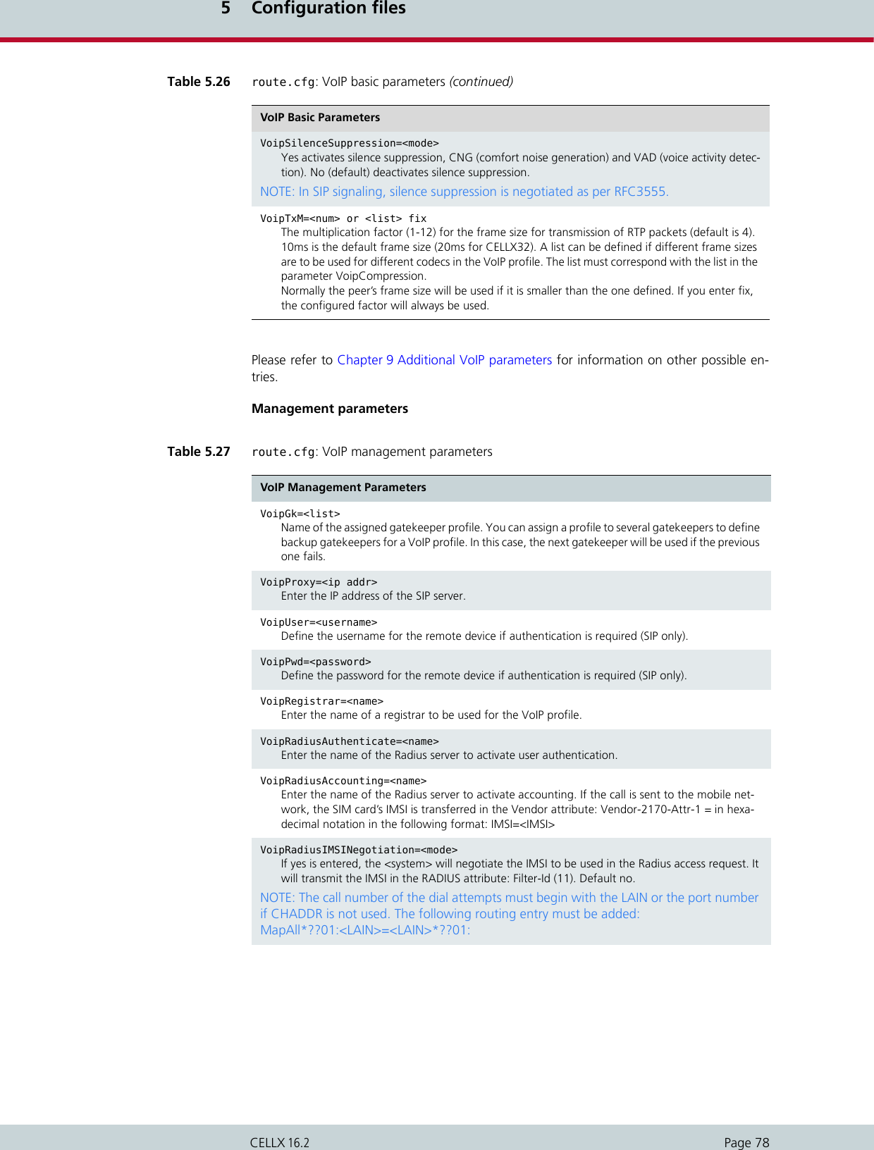
![5 Configuration filesPage 79CELLX 16.25.3.3 Gatekeeper profilesGatekeeper profiles are used to connect the CELLX to several systems by using a gatekeeperif the protocol is H.323. It is possible to configure different gatekeepers for different destina-tions and to define backup gatekeepers. These gatekeeper profiles are then assigned to theVoIP profiles.VoipIpLogging=<mode>Enter Yes to activate recording IP addresses in the CDRs (default is No). The first IP address is the signaling address and the second is the RTP address, followed by the the codec and the frame size used. The IMSI appears after the IP addresses if the keyword IMSI is defined in the pabx.cfg.Example of a CDR entry:21.08.07-11:01:42,21.08.07-11:01:58,40,912345,192.168.0.2:192.168.0.2,G729,10,0101,16,10,0Example of a failed log entry:21.08.07-11:11:30,40,91234,192.168.0.2:192.168.0.2,G729,10,0101,ff,2,1VoipStatLogging=<mode> When Yes is entered, statistic values (for example fraction lost, round trip time, and so on) for the VoIP profile are saved into the protocol.log file every ten minutes. This is helpful during problem analysis when IP issues occur (default = No).VoipHold=<mode>Determines the behavior of the HOLD feature if a PBX sends an Re-INVITE message for HOLD to the gateway.transparent: HOLD is sent to PSTNnotify: HOLD is sent as notification to the telephone exchangeignore: HOLD is not sent to the telephone exchange - the gateway suppresses the messages to PSTNVoipSelectProfilesBySignalling=<Yes/No>When Yes is entered, VoipSignalling=<int> is taken as the criterion for selecting a voip-profile for an incom-ing voip call, i.e. the signalling for this voip call must match the VoipSignalling param-eter in this profile. Default No.Table 5.27 route.cfg: VoIP management parameters (continued)VoIP Management ParametersTable 5.28 route.cfg: gatekeeper parameters Gatekeeper Parameters[Gatekeeper:<name>]Name of the gatekeeper profile.RasPort=<port>Indicates the port the gatekeeper uses (default 1719) for registration, admission and status.OwnRasPort=<port>Indicates the port the system uses (default 1719) for registration, admission and status.RasPrefix=<list>CELLX’s defined prefix(es). Use a space to separate entries.RasId=<name>The alias used for gatekeeper registration.GkId=<name>The gatekeeper’s alias.](https://usermanual.wiki/Teles-Informationstechnologien/CDMA32VOIPUS/User-Guide-1599912-Page-81.png)
![5 Configuration filesPage 80CELLX 16.25.3.4 Registrar profilesRegistrar profiles are used to register the CELLX with a SIP registrar. It is possible to configuredifferent registrars for different destinations and to define backup registrars. These registrarprofiles are then assigned to the VoIP profiles.GkPwd=<name>Password to log onto the gatekeeper. If you do not use authentication, leave this entry blank.GkAdd=<ip addr>The gatekeeper’s IP address.GkTtl=<sec>Gatekeeper time to live (default 0 means infinite).GkMaxChan=<count>Max. number of channels used for this gatekeeper. If this parameter is not defined (default), there will be no limit.GkDynMaxChan=<mode>The static number of available channels in the gatekeeper profile (GkMaxChan=<count>) is re-placed with a dynamic number of active mobile ports (up to the number entered in GkMaxChan) when Yes is entered here. Default is No.GkUseStun=<mode>Enter yes (default) to use the STUN values for the GK profile.GkTerminalAliasWithPrefix=<mode>Some gatekeepers may require that prefixes are listed in the Terminal Alias section. Enter Yes to activate this function; default value is No). GkTerminalTypeWithPrefix=<mode>Enter no to deactivate sending the Dialed Prefix Information in the Registration Request (default yes).GkDynRai=<mode>When yes is entered, the GK receives an RAI (resource availability indication) when a status change occurs on the available mobile channels. When no is entered, the RAI is sent with each ARQ (admission request) and DRQ (disengaged request). Default is no.GkNoResourceAvailableIndication=<mode>With this parameter the <system> will not send RAI indications to the Gatekeeper. Default No.Table 5.28 route.cfg: gatekeeper parameters (continued)Gatekeeper ParametersTable 5.29 route.cfg: registrar parameters Registrar Parameters[Registrar:<name>]The name of the registrar profile.RegId=<name or ip addr>Host name or IP address used in the register’s request header. Bear in mind that the DNS service must be active if you enter the host name.RegOwnId=<name@ip addr/domain>Typically a host name or telephone number followed by an @ sign and a domain name or IP ad-dress. The entry used in the From: field. The default setting is RegUser@RegId.](https://usermanual.wiki/Teles-Informationstechnologien/CDMA32VOIPUS/User-Guide-1599912-Page-82.png)
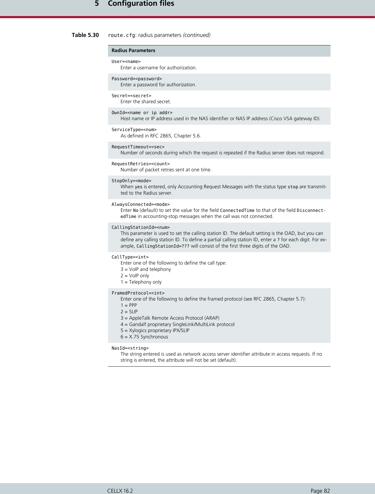
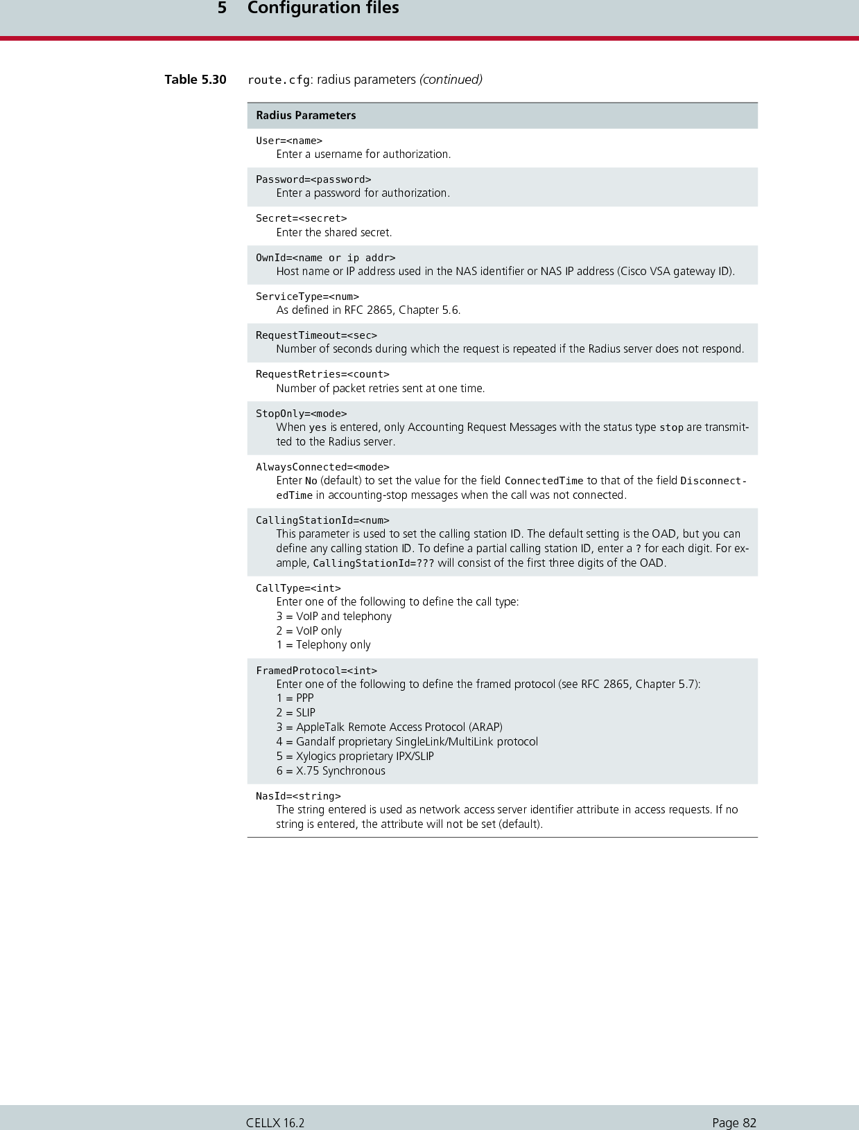
![5 Configuration filesPage 81CELLX 16.25.3.5 Radius profilesRadius profiles are used to connect the CELLX to a Radius server. You can use a Radius serverfor different destinations and for access and/or accounting. These Radius profiles are then as-signed to the VoIP profiles.RegSameCallID=<mode>When Yes is set (default), the same caller ID is always used for SIP registration. Set No to change the caller ID for each SIP registration.RegContact=<name or ip addr>Used in the Contact: field.RegContactParam=<string>Sets additional header-parameters in the contact field (for example the q-value: RegContact-Param=q=1.0).RegUser=<name>Enter a username for authorization.RegPwd=<password>Enter a password for authorization.RegProxy=<ip addr>Enter an alternative IP address if you want the request to be sent to an address other than the one entered in RegId.RegExpires=<sec>Enter the number of seconds registration is to be valid. Default 0 means infinite.RegPing=<sec>Interval (in seconds) for the registrar ping. The CELLX sends an empty UDP packet to the registrar’s IP address. The packet is essentially an alive packet to avoid possible firewall problems.RegSignalling=<int>Determines the profile’s signaling protocol for registration with the SIP registrar. 1=SIP udp (default)2=SIP tcp3=SIP tlsRegUseReceived=<mode> Enter Yes when an CELLX appears behind a NAT and STUN cannot be used. Default No..RegSameCallID=<mode> The same call ID is used for SIP registration Enter No to change the call ID for every reregistration. (default Yes).Table 5.29 route.cfg: registrar parameters (continued)Registrar ParametersTable 5.30 route.cfg: radius parameters Radius Parameters[Radius:<name>]The name of the Radius server profile assigned to one or more VoIP profiles.Host=<name or ip addr>Radius server’s host name or IP address. Bear in mind that the DNS service must be active if you enter the host name.](https://usermanual.wiki/Teles-Informationstechnologien/CDMA32VOIPUS/User-Guide-1599912-Page-83.png)
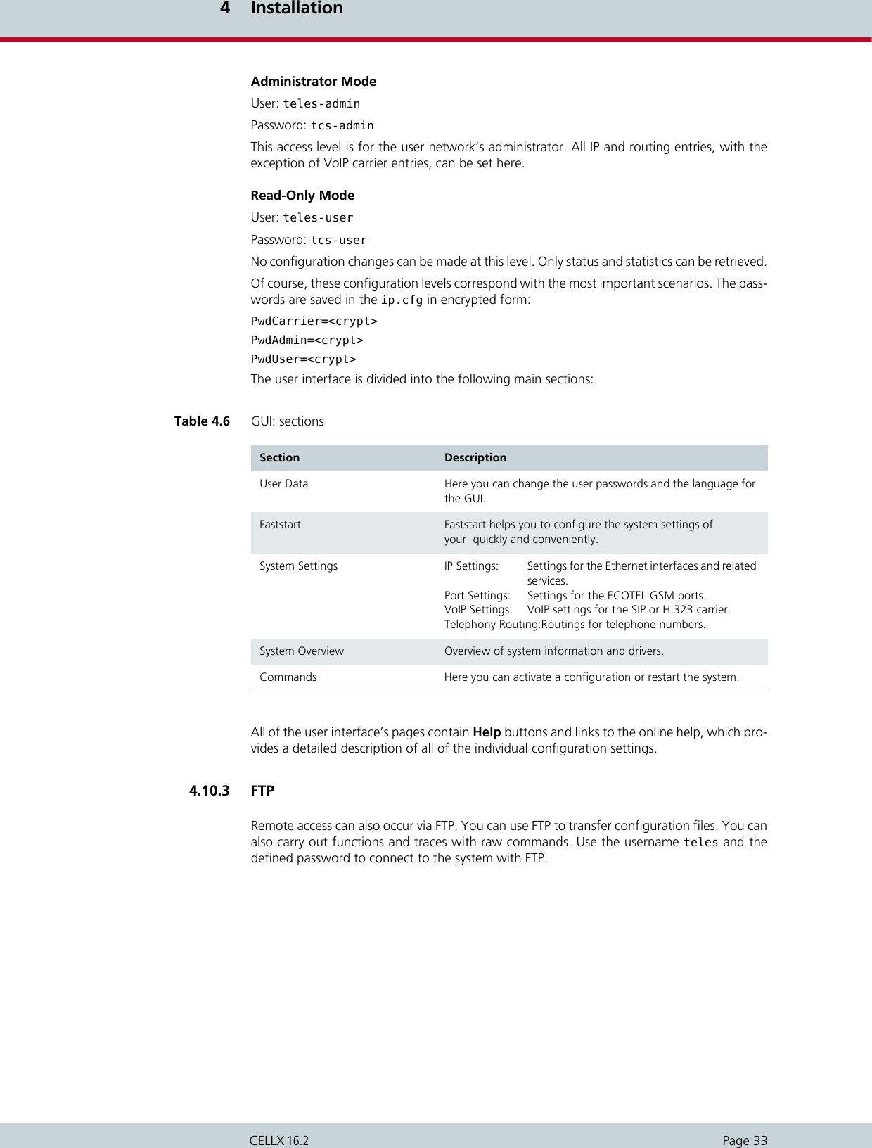
![6 Routing examplesPage 84CELLX 16.26.1 CELLX integration in an H.323 carrier networkIn the following example, an CELLX32 is integrated in a carrier network via H.323. The systemcontains six SIM cards for each mobile channel, and the SIM 24 Carrier is used. All calls com-ing from VoIP are routed to the mobile network. Four VoIP Modules with 16 media channelseach are attached in the system. H.323 is used as the signaling protocol and a gatekeeper isused in the VoIP network. Because the gatekeeper assigns and authorizes the peer, only oneVoIP profile is necessary. Since the peers may use various compression algorithms, you candefine several if you so choose. The codec with the highest priority is G.729. If the peer doesnot support it, G.726 32Bit/sec, G.711a, G.711u are also possible. Silence suppression is ac-tive. The gatekeeper’s IP address is 192.168.0.10. This gatekeeper profile can handle up to30 simultaneous VoIP calls. This value is dynamic and changes depending on the number ofactive SIM cards. The CELLX’s alias is iGATE01. The prefix list is 01555 01556 01444 01445.The gatekeeper’s alias is GK1 and no password is used. Calls with the prefixes 01555 and01556 are sent to the carrier with the LAIN 26212 at controllers 0-15. Calls with the prefixes01444 and 01445 are sent to the carrier with the LAIN 26313 (controllers 16-31). Digit col-lection is activated, so that incoming calls with overlap dialing are not transmitted until thenumber is complete or a wait timer (5 seconds) has run out. The NEXT parameter makes surethat calls are distributed evenly to the individual mobile channels in the trunk group. The pa-rameter CHADDR ensures that calls are not misrouted, since the controller definition changesto the SIM card’s LAIN when a SIM card is mistakenly used for another mobile controller.Problems can occur when SMS messages are also sent, as service center numbers are defini-tively configured. The parameter LIMIT is set so that the system automatically switches to themobile controllers’ SIM cards when the active SIM card has been used for 3600 seconds. Theparameter CONTINUE makes sure the mobile channel switches to the first SIM card after thelimit has been reached on the last SIM card. The SIM card will not switch until currently activecalls have been disconnected.Figure 6.1 CELLX integration with SIM card switching in an H.323 carrier networkExample 6.1 CELLX integration with SIM card switching in an H.323 carrier network (pabx.cfg)Subscriber00 = TRANSPARENT ROUTER GSM[0000,00000,+00000,1,1,1,SIM24] CHADDR LIMIT[3600,3600,3600,3600,3600,3600] CONTINUE ALARM NEXTSubscriber01 = TRANSPARENT ROUTER GSM[0000,00000,+00000,1,1,1,SIM24] CHADDR LIMIT[3600,3600,3600,3600,3600,3600] CONTINUE ALARM ....Subscriber34 = TRANSPARENT ROUTER SWITCH CHMAX[16] ALARMSubscriber35 = TRANSPARENT ROUTER SWITCH CHMAX[16] ALARMChargeUnitGenerate=1LimitWODisc=ON](https://usermanual.wiki/Teles-Informationstechnologien/CDMA32VOIPUS/User-Guide-1599912-Page-86.png)
![6 Routing examplesPage 85CELLX 16.26.2 CELLX as a second-generation LCR with VoIPIn the following example of a PBX connection, all mobile calls are terminated through the mo-bile channels. Eight mobile channels form a group for one mobile network. One SIM card isavailable on each mobile channel. Digit collection is activated, so that incoming calls withoverlap dialing are not transmitted until the number is complete or a wait timer (5 seconds)has run out. The NEXT parameter makes sure that calls are distributed evenly to the individualmobile channels in the trunk group. If all of a carrier’s SIM cards are busy, rerouting(redirect3) via PSTN is automatically initiated. All international calls are terminated to VoIP(40). The system contains two VoIP Modules, for a total of 32 media channels. The VoIP car-rier profile DF and the SIP protocol are used. National calls are routed through the carrier withthe prefix 010xx. All other calls are sent to the PSTN unchanged. All calls from the PSTN orfrom a VoIP carrier are sent directly to the NT controller, to which the PBX is attached. All in-coming calls from the mobile networks are routed to the PBX’s central number (001). For theExample 6.2 CELLX integration with SIM card switching in an H.323 carrier network (route.cfg)[System]DTMFWaitDial=5MapAll01555=|2621201555<<17MapAll01556=|2621201556<<17MapAll01444=|2621301444<<17MapAll01445=|2621301445<<17[Voip:DF]VoipDirection=InVoipPeerAddress=10.0.0.0VoipIpMask=0xffff0000VoipSignalling=0VoipCompression=g729 g72632 g711a g711uVoipSilenceSuppression=YesVoipMaxChan=30VoipTxM=2VoipGk=GK1[Gatekeeper:GK1]RasPort=1719OwnRasPort=1719RasId=iGATE01RasPrefix=01555 01556 01444 01445GkId=GKGkAdd=192.168.0.10GkPwd=GkTtl=300GkMaxChan=30GkDynMaxChan=Yes](https://usermanual.wiki/Teles-Informationstechnologien/CDMA32VOIPUS/User-Guide-1599912-Page-87.png)
![6 Routing examplesPage 86CELLX 16.2VoIP profile DF, the system uses the registrar reg and registers with user@sip-carrier.de,username user and password pwd. SIP UDP is used for signaling. A maximum of 30 mediachannels with the G.729 codec can be used. The Peer is sip-carrier.de.Figure 6.2 CELLX as a second-generation LCR with VoIPExample 6.3 CELLX as a second-generation LCR with VoIP (pabx.cfg)Subscriber00 = TRANSPARENT ROUTER GSM[0000,00000,+00000,1,1,1,SIM4] CHADDR ALARM NEXTSubscriber01 = TRANSPARENT ROUTER GSM[0000,00000,+00000,1,1,1,SIM4] CHADDR ALARM ....Subscriber08 = TRANSPARENT ROUTER GSM[0000,00000,+00000,1,1,1,SIM4] CHADDR ALARM NEXTSubscriber09 = TRANSPARENT ROUTER GSM[0000,00000,+00000,1,1,1,SIM4] CHADDR ALARM ....Subscriber16 = TRANSPARENT ROUTER ALARMSubscriber17 = TRANSPARENT ROUTER ALARMSubscriber18 = TRANSPARENT ROUTER SWITCH CHMAX[16] ALARMSubscriber19 = TRANSPARENT ROUTER SWITCH CHMAX[16] ALARM](https://usermanual.wiki/Teles-Informationstechnologien/CDMA32VOIPUS/User-Guide-1599912-Page-88.png)
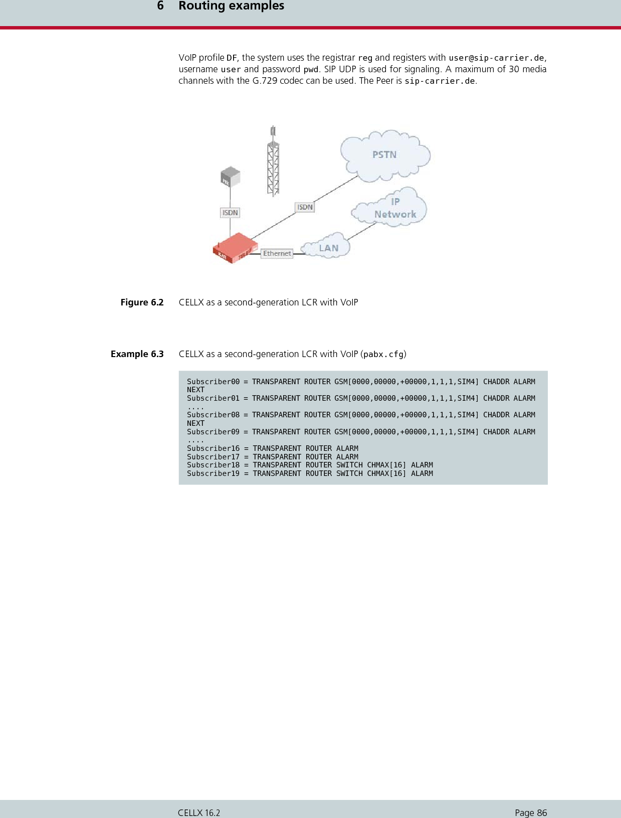
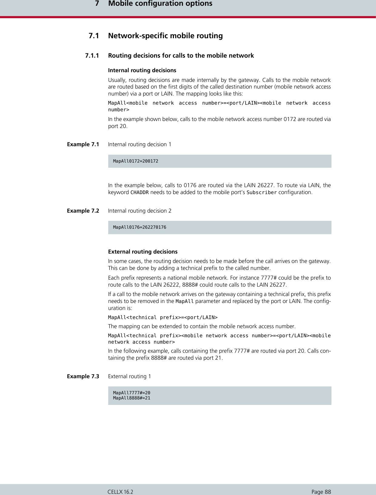
![7 Mobile configuration optionsPage 89CELLX 16.2In the following example, calls which come in with the prefix 9999# and the mobile networkaccess number 0176 are routed via the LAIN 26227 to 0176.7.1.2 Using the LAIN as the mobile port addressUse the LAIN as controller with the CHADDR parameter to prevent logging onto the wrongSIM card. This will ensure that routing is network specific. The following example is based onthe German country code. One carrier’s LAIN is 26212 and the other carrier’s LAIN is 26213.Example 7.4 External routing 2MapAll9999#0176=262270176Example 7.5 Using the LAIN as the mobile port address (pabx.cfg)...Controller00=20 GSMController01=20 GSMController02=20 GSMController03=20 GSMController04=20 GSMController05=20 GSMController06=20 GSMController07=20 GSM...Subscriber00=TRANSPARENT ROUTER GSM[0000,00000,+49556,1,1,1,SIM4] CHADDR ALARMSubscriber01=TRANSPARENT ROUTER GSM[0000,00000,+49556,1,1,1,SIM4] CHADDR ALARMSubscriber02=TRANSPARENT ROUTER GSM[0000,00000,+49556,1,1,1,SIM4] CHADDR ALARMSubscriber03=TRANSPARENT ROUTER GSM[0000,00000,+49556,1,1,1,SIM4] CHADDR ALARMSubscriber04=TRANSPARENT ROUTER GSM[0000,00000,+49555,1,1,1,SIM4] CHADDR ALARMSubscriber05=TRANSPARENT ROUTER GSM[0000,00000,+49555,1,1,1,SIM4] CHADDR ALARMSubscriber06=TRANSPARENT ROUTER GSM[0000,00000,+49555,1,1,1,SIM4] CHADDR ALARMSubscriber07=TRANSPARENT ROUTER GSM[0000,00000,+49555,1,1,1,SIM4] CHADDR ALARM...If you remove the keyword CHADDR from the pabx.cfg, you must restart the system. Control-lers belonging to the same trunk group must have the same address. You must delete all rout-ing entries based on port addresses when using the LAIN as controller.Example 7.6 Using the LAIN as the mobile port address (route.cfg)...MapAll01555=2621201555...MapAll01556=2621301556...ii](https://usermanual.wiki/Teles-Informationstechnologien/CDMA32VOIPUS/User-Guide-1599912-Page-91.png)
![7 Mobile configuration optionsPage 90CELLX 16.27.1.3 Fixed LAIN for a mobile portEnter CHADDR[<addr>] to remove a mobile controller belonging to an LAIN group from thestandard routing process (for example for specific routes or only for SMS transmission). Theport address can be set to <addr>.7.2 Incoming voice calls from mobileIncoming mobile calls (service indicator 01 represents voice calls) can be routed to a specifiednumber. This enables each mobile controller to receive a unique identifier. It will then bemapped to a number.The mobile controllers can also have the same identifier, so that all voice calls (service indica-tor 01) from controller 20 are sent to number 1111 at port 9. This number could, for example,serve a call center.7.3 Blocking portsThis function allows you to block a port, so that the corresponding mobile channel is omittedfrom the distribution of calls. The function is particularly useful when mobile channels fail orSIM cards cannot be immediately replaced. To disable the port for outgoing calls enter the keyword CHINC[01,01] in the Subscriberline and restart the system. In the following example, port 04 is blocked for outgoing calls.Example 7.7 Fixed LAIN for a mobile portSubscriber05=TRANSPARENT ROUTER GSM[0000,00000,+49555,1,1,1,SIM4] CHADDR[444] ALARMMapAllSMS=444 DATAThe value entered for <addr> may not exceed 6 digits.iiExample 7.8 Incoming voice calls from mobile 1Restrict20=90123 01Restrict21=91234 01Example 7.9 Incoming voice calls from mobile 2Restrict20=91111 01](https://usermanual.wiki/Teles-Informationstechnologien/CDMA32VOIPUS/User-Guide-1599912-Page-92.png)
![7 Mobile configuration optionsPage 91CELLX 16.2To enable the port for outgoing calls, remove the entry and enter Activate Configuration.7.4 Mobile user PBX callbackWhen the CELLX is implemented in a corporate network and connected to a PBX or betweena PBX and the outside line, the following configuration entry activates a feature, that uses amobile caller’s OAD to connect with the last PBX extension the caller unsuccessfully dialed.DialBack=<hours>The callback list is active for the number of hours entered. DialBackMinutes=<minutes>The callback is active for the number of minutes entered. After that time, the callback recordis deleted in the system.DialBackStopOnConnect=<mode>Deletes (On) the dialback record once a dialback call is connected. Off deactivates this behav-ior.DialBackCompare=<digits> Shows the number of digits at the end of a phone number that are compared during dialbackhandling. The default value is 10. Comparison of the end part of numbers is necessary whenthe same number is displayed differently (when, for instance, one version includes the countrycode, but the other doesn’t).For calls coming from VoIP, add the following parameter to the used VoIP profile:VoipOadIn=<name of profile used for callback>:Enter the name of the VoIP profile that you use to call back the extension.In the following example, the callback list is active for the previous five hours. The Germancountry code is used for the LAINs. All calls with the prefixes 1111 and 2222 are terminatedthrough the carrier with the LAIN 26212. Calls with the prefix 3333 are terminated throughthe carrier with the LAIN 26213.Example 7.10 Blocking ports...Subscriber04=TRANSPARENT ROUTER [0000,00000,<SMSC>,1,1,1,SIM4] CHADDR ALARM CHINC[01,01]...Incoming calls are always possible. The status is not displayed in the GATE Manager.iiExample 7.11 Mobile user PBX callbackDialBack=5MapAll1111=262121111MapAll2222=262122222MapAll3333=262133333](https://usermanual.wiki/Teles-Informationstechnologien/CDMA32VOIPUS/User-Guide-1599912-Page-93.png)
![7 Mobile configuration optionsPage 92CELLX 16.27.5 Optional mobile quality parametersThe following parameters can be set for specific carriers if SIM cards for different mobile net-works are used and different configurations must be set.For all controllers without a LAIN, the following default setting applies: GSM=Up to four additional carrier-specific entries may be set:GSM1=<Lain1> ALFI[<val1/val0>]...GSM2=<Lain2> ...GSM3=<Lain3> ...GSM4=<Lain4> ...Up to four LAIN-specific configurations are possible. The user must enter the index (1 to 4).The LAIN appears as the first entry behind the equal sign. Everything else follows.The following table describes specific signaling and quality parameters for configuration ofthe mobile interface. Make sure that no Restrict entries are configured for these mobile controllers.iiBear in mind that for iGATE UMTS you must use the keyword UMTS= instead of GSM=!The following syntax applies: UMTS1=<Lain1> ALFI[<val1/val0>]...iiThere is no automatic default behavior for this feature! All options must always be entered. We recommend that you enter GSM= settings, as all controllers without a LAIN or with a de-fault address use these options!iiTable 7.1 Optional mobile parameters GSM=... (for iGATE GSM) or UMTS= … (for iGATE UMTS)Enter any of the following parameters after the equal sign for the following functions. Entries may appear in any order, but all entries must appear in the same line and in double-digit notation as fol-lows:GSM=RSSI[10] STOP[18,08] ANNOUNCE[00,08] FAX[a2] ASR[20,35]or UMTS=RSSI[10] STOP[18,08] ANNOUNCE[00,08] FAX[a2] ASR[20,35]ALERT[<sec>] Set this parameter to generate an alert signal in the D channel im-mediately after the dial-end signal. If you enter optional square brackets containing a number of seconds, the alert signal will oc-cur when the number entered has passed following setup.](https://usermanual.wiki/Teles-Informationstechnologien/CDMA32VOIPUS/User-Guide-1599912-Page-94.png)
![7 Mobile configuration optionsPage 93CELLX 16.2ANNOUNCE Set this parameter to define what happens when a recorded an-nouncement is detected:No ANNOUNCE entry (default)A D-channel PROGRESS message stating Inband Information Available will be generatedANNOUNCE[<cause>]The connection will be rejected with the defined ISDN cause value. Do not enter the cause value ff!ANNOUNCE[00,<sec>]A timeout for voice detection is defined in seconds (default value: 120 seconds). After the interval entered has passed, the connection is torn down.ANNOUNCE[ff]The call will be connected as soon as an announcement is de-tected.FORWARD[<cause>] For GE864-QUAD modules onlyThe connection will be rejected with the defined ISDN cause value when call forwarding is detected.NOTE: The GSM network must support this feature for it to work.ASAL Announcement Stop during ALert: Set this parameter to release calls if the GSM network sends an alert message, after which voice is detected (for example the B-party rejects the call, which is then forwarded to the B-party’s voicemail following the ring state).The parameter ANNOUNCE[<cause>] must be set to activate this parameter.MINV[<count>] Minimum Voice detections: Parameter used with ASAL to define the number of voice detections in a row before the call is released (for example GSM-network background noise detected as voice). The default value is 1, but 2 is recommended.The parameters ANNOUNCE[<cause>] and ASAL must be set to activate this parameter.ASR[<limit>,<calls>]Allows you to change the default value (40 calls at 30% ASR). For a definition of ASR, see Chapter 11.4.1 Generating and retrieving CDRs.CDC[<seconds>,<count>]Call duration check. When more than (<count>) connected calls in a row occur with a call duration lower than <seconds>, an alarm is generated and the port is restarted.FAX[<cause>] This entry allows you to reject fax calls with the defined cause val-ue.RSSI[<limit>] Configure this parameter to set a limit for the reception field strength. When the reception field strength falls below this limit, the mobile channel will be blocked. If the field strength is above the limit, the mobile channel will log on with the mobile carrier again. The values used are 0 to 31, which represent the following field strengths: -113dBm to -51 dBm. An error is generated in the protocol log. The result must be divided by 2.EXAMPLE: To define a field strength of -95 dBm, subtract -95 from-113 and divide the result by 2:- 113dB - (-95dB) = -18dB / 2 = 9Enter RSSI[9]Table 7.1 Optional mobile parameters (continued)GSM=... (for iGATE GSM) or UMTS= … (for iGATE UMTS)](https://usermanual.wiki/Teles-Informationstechnologien/CDMA32VOIPUS/User-Guide-1599912-Page-95.png)
![7 Mobile configuration optionsPage 94CELLX 16.2STOP[<val1>,<val2>]This entry allows you to define a maximum number of connection setups that always result in a recorded message (<val1>) without an alert detection or call-connected signal. The second value (<val2>) counts calls that connect immediately without an Alert detection. The mobile port is blocked when the defined value is reached and an entry is recorded in the log file (...Err: Voice). In this way inactive SIM cards that are forwarded to a recording (with or without a connect from the mobile carrier) can be detected and blocked so that they are removed from the routing process. The default status of this function is off.NOCP When this option is configured and the call is from ISDN to GSM, the Call Proceeding signaling message will be eliminated from sig-naling. This may be necessary if the ISDN peer does not support Call Proceeding. Bear in mind that the peer’s Setup Ack Timer is usually set at 5 seconds, which means that an Alert must be gen-erated as follows: GSM=ALERT[5] (for iGATE GSM)UMTS=ALERT[5] (for iGATE UMTS)FMIN[xxx] FMAX[yyy] Sets the frequency range for ringtone detection (default 400-444 Hz).EXAMPLE:GSM=FMIN[400] FMAX[444] (for iGATE GSM)UMTS=FMIN[400] FMAX[444] (for iGATE UMTS)ALFI[<val1/val0>] GSM module GE864-QUAD only. Switches the digital filter on (val=1) the Telit module to suppress frequencies below 250 Hz per LAIN during alerting. (switch off val=0)Please use the parameter to enable alert-tone detection for dual tone LAINs only (please see Chapter 7.5 Optional mobile quality parameters).VOICE[<sec>] The voice channel in the switching matrix is connected after <sec> (default immediately). The voice channel is activated no later than the point at which the call is connected.WND9 Voice detection is activated in the GSM module if the GSM net-work signals WND9 (voice). If this parameter is not set, voice de-tection is activated immediately when the GSM call is initialized.Module Q24xx only.WND2A Generates Alert when WIND:2 is received. Module Q24xx only.WND2N Suppresses voice detection after WIND:2 is received. Module Q24xx only.MINA[<count>] Defines the number of alert tones that are required before an Alert is detected.Table 7.1 Optional mobile parameters (continued)GSM=... (for iGATE GSM) or UMTS= … (for iGATE UMTS)](https://usermanual.wiki/Teles-Informationstechnologien/CDMA32VOIPUS/User-Guide-1599912-Page-96.png)
![7 Mobile configuration optionsPage 95CELLX 16.27.6 Deactivating mobile rerouting Use the following entries in the pabx.cfg to deactivate rerouting for rejected calls.REDIAL[<percent>,<waitmin>,<waitmax>,<callingmin>,<callingmax>,<connectmin>,<connectmax>,<cfg>]Repeats a call to the same B-party number as soon as the A party hangs up. This parameter is useful for improving call statistics:Percent: Percentage of calls (including alert only)through the gateway that are redialed.Waitmin: Minimum number of seconds thegateway waits before redial.Waitmax: Maximum number of seconds thegateway waits before redial.Callingmin: Minimum number of seconds thegateway waits before call setup for redial. Werecommend no more than 8 seconds.Callingmax: Maximum number of seconds thegateway waits before call setup for redial. Werecommend no less than 15 seconds.Connectmin: Minimum connect time (in seconds) ifcall is connected.Connectmax: Maximum connect time (in seconds)before call is disconnected.Cfg: Enter a value 1 – 4; valid for the 1= line to 4= linefor the iGATE GSM, or for the 1= line to 4= line forthe iGATE UMTS. CPSA[0|1] When CPSA ist set to 0, the GSM port is forced to register the SIM card to it’s home network, which is identified by the first 5 or 6 digits of the IMSI. This may result in a faster registration process. CPSA[1] is the default value.Table 7.1 Optional mobile parameters (continued)GSM=... (for iGATE GSM) or UMTS= … (for iGATE UMTS)Table 7.2 Deactivating mobile rerouting ParametersAllClassNext=<mode>Enter AllClassNext=Off to deactivate rerouting for all rejected calls, regardless of the cause value (default not configured).NOTE: You cannot configure both AllClassNext and Class2Next simultaneously!Class2Next=offEnter Class2Next=Off to deactivate rerouting for calls rejected with a class 2 cause value (default not configured).NOTE: You cannot configure both AllClassNext and Class2Next simultaneously!SelfNext=<int>Set this parameter to reroute a failed call through the same port. <int> defines the number of call attempts. Recommended values for <int> are 2 or 3. Bear in mind that this parameter must be used in conjunction with the parameter AllClassNext=Off. Default not configured.EXAMPLE: SelfNext=3AllClassesNext=Off](https://usermanual.wiki/Teles-Informationstechnologien/CDMA32VOIPUS/User-Guide-1599912-Page-97.png)
![7 Mobile configuration optionsPage 96CELLX 16.27.7 Setting autodialWhen the following configuration is set, the gateway calls a defined list of phone numbersautomatically. Save the script in a text file with the extension *.ad.The autodial process starts automatically when the script file has been copied to /boot or /data. The file extension is renamed *.ax and is deleted when process has ended. A log file*.al is generated in the course of the process. The file contains whether the call was success-ful, the number called, the call duration for successful calls, and the cause value for failedcalls. To abort the process, simply delete the *.ax file.The following settings are possible:OPTION CALLDURATION: Enter an interval in seconds to define the length of the call.OPTION CALLRETRIES: Enter the number of call attempts for each number.OPTION CONFIGURATION: Refers to the number of the = configuration.OPTION NOALARM: Set this option to suppress sending alarms when connected to avGATE.D<sec>: Enter a value to define the duration for calls to this number.P<sec>: Enter a value to define the pause between calls.7.8 Disconnecting calls after ringWhen the following parameter is configured, the call will be disconnected once the numberof configured seconds have passed after the mobile network has sent the first ring:AWSTime=<sec>7.9 Checking ports/mobile channelsMonitoring ASR for mobile portsASR monitoring of the last 40 calls occurs for all mobile ports. If the ASR (ASR2) is lower than30 percent, an alarm is generated at the corresponding port and the port is blocked. The portis then restarted and a corresponding entry appears in the protocol.log file (ASR). The port isthen unblocked.The following entry in the pabx.cfg causes the mobile port to block automatically when thiserror occurs three times in a row:ASRBlock=OnWhen ASRBlock=Off is used, the port will be restarted and will remain open.The following parameter in the pabx.cfg file allows you to change the default value (30%for 40 calls): GSM=ASR[<percent>,<number of calls>] (for iGATE GSM)Example 7.12 Setting autodialOPTION CALLDURATION 155-170OPTION CALLRETRIES 2 OPTION CONFIGURATION 1OPTION NOALARM 017222921 D10 P30017222922 D10 P30017222923 D10 P30017222924 D10 P30](https://usermanual.wiki/Teles-Informationstechnologien/CDMA32VOIPUS/User-Guide-1599912-Page-98.png)
![7 Mobile configuration optionsPage 97CELLX 16.2UMTS=ASR[<percent>,<number of calls>] (for iGATE UMTS)7.10 Defining special characters for voice callsIn cases in which the called number includes special characters (for example * or #), it may benecessary to define the call type used in the mobile network (command or voice call). Calls toGSM or CDMA that begin with * or #, are sent as command calls by default. For voice callsbeginning with * or #, you must define the call type voice in the mapping entry with a > sign.The routing entry will look like this:MapAll<num>=<LAIN>><num>Example 7.13 Monitoring ASR for mobile ports (iGATE GSM)GSM=ASR[20,35]Example 7.14 Monitoring ASR for mobile ports (iGATE UMTS)UMTS=ASR[20,35]Example 7.15 Defining special characters for voice callsMapAll222=11111>*222](https://usermanual.wiki/Teles-Informationstechnologien/CDMA32VOIPUS/User-Guide-1599912-Page-99.png)
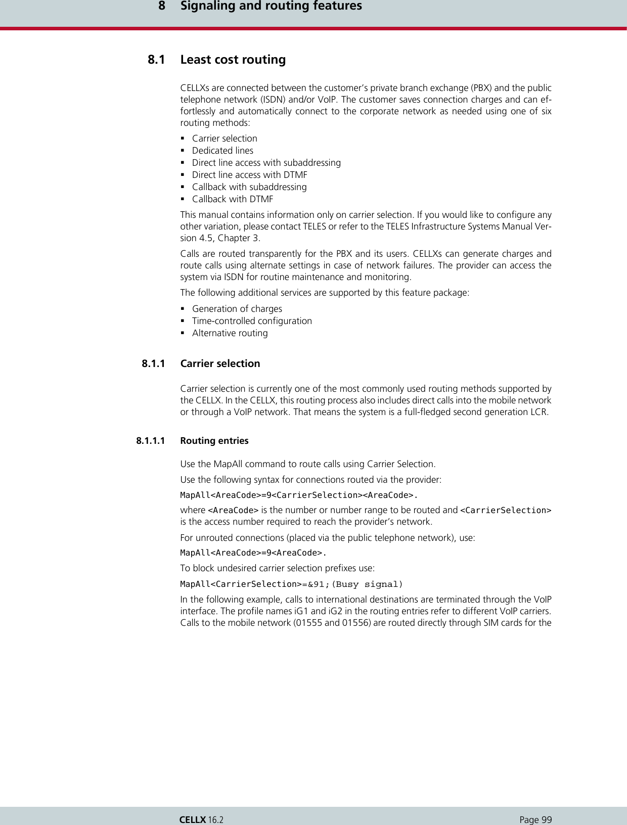
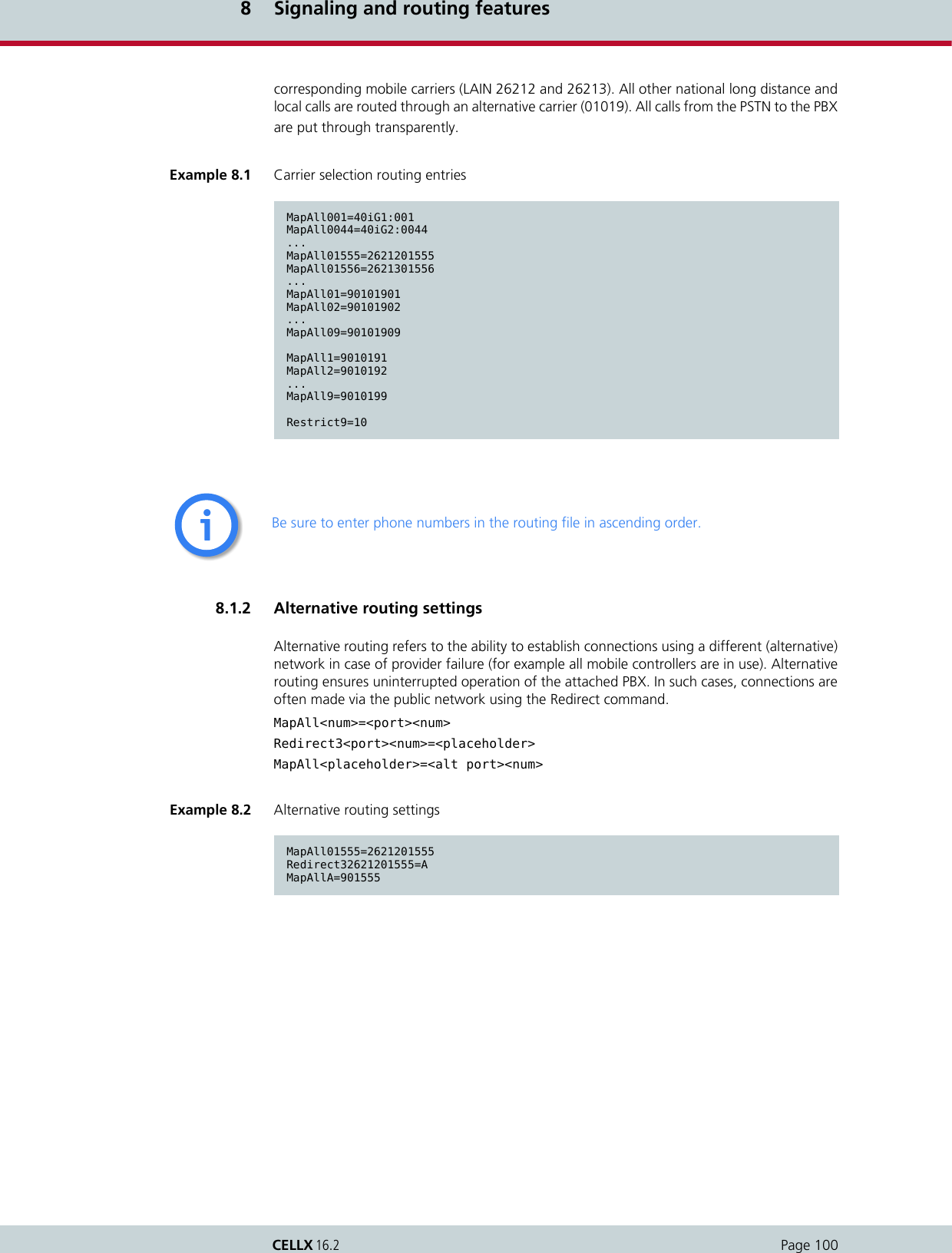
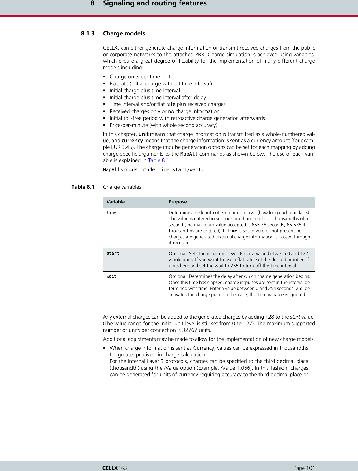
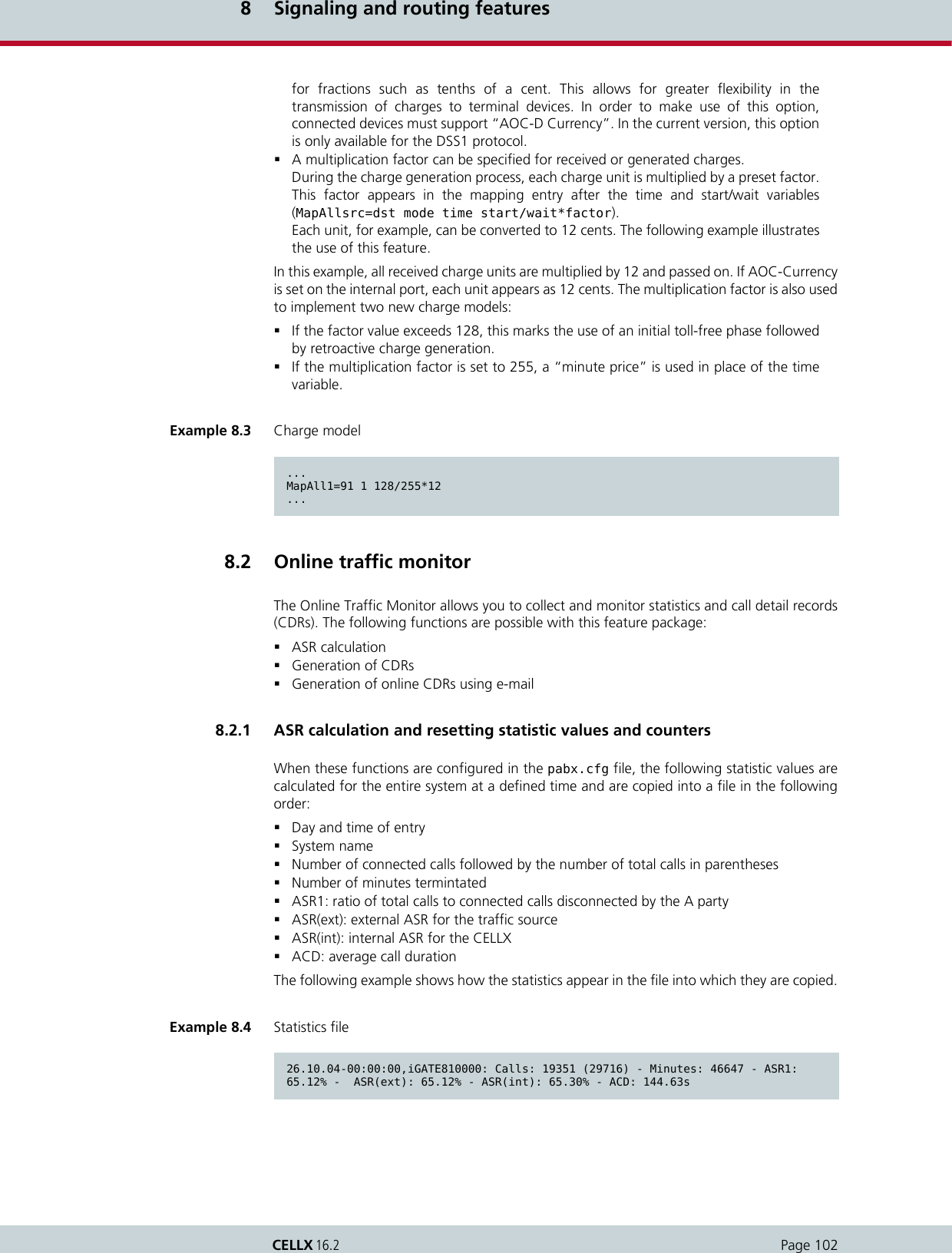
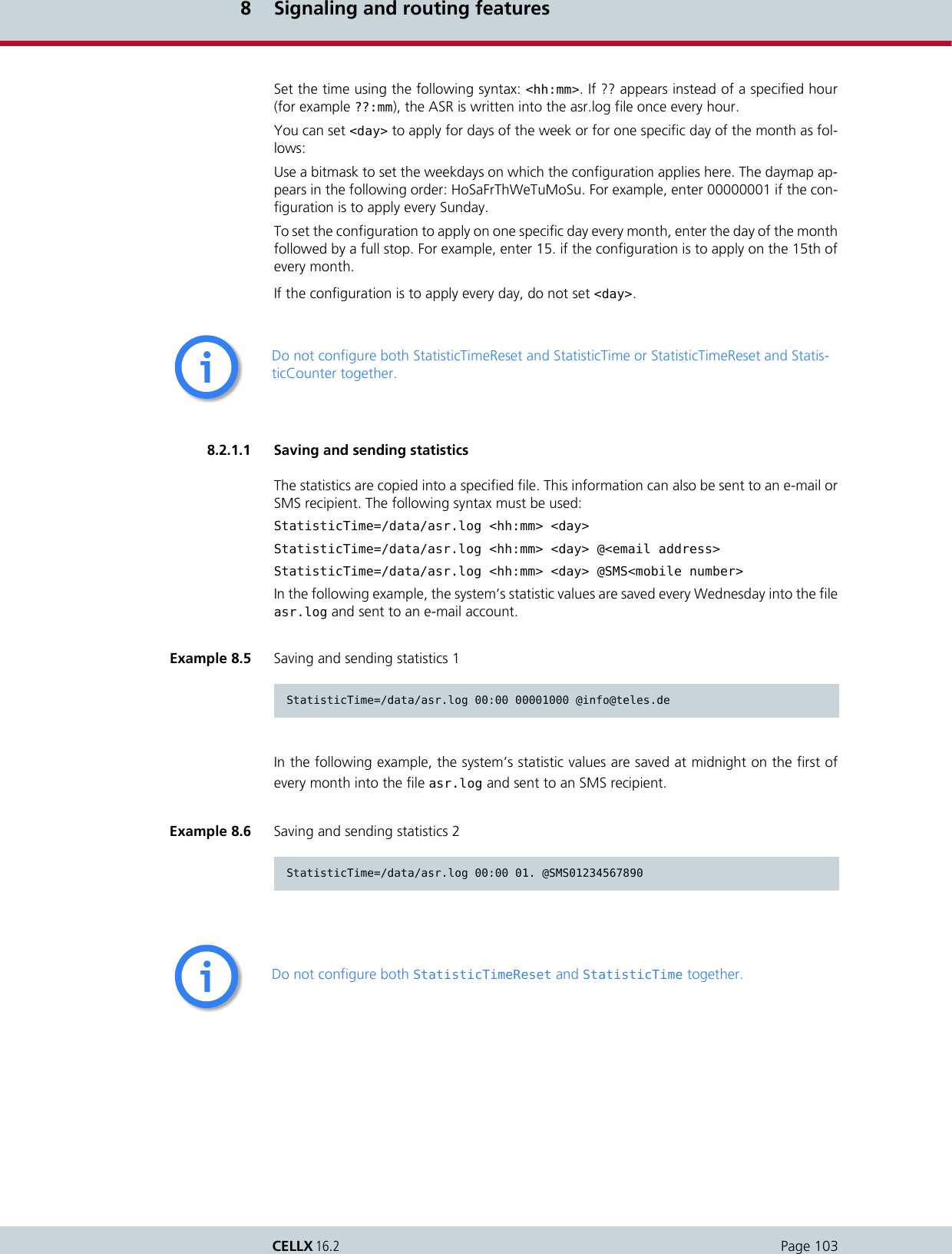
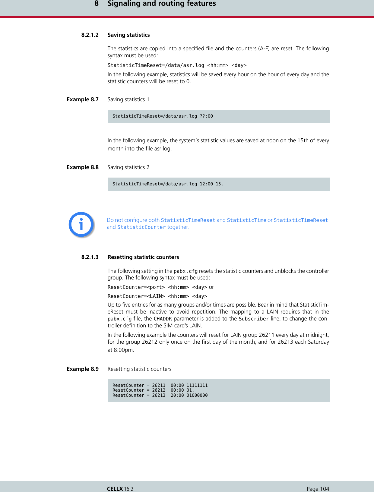
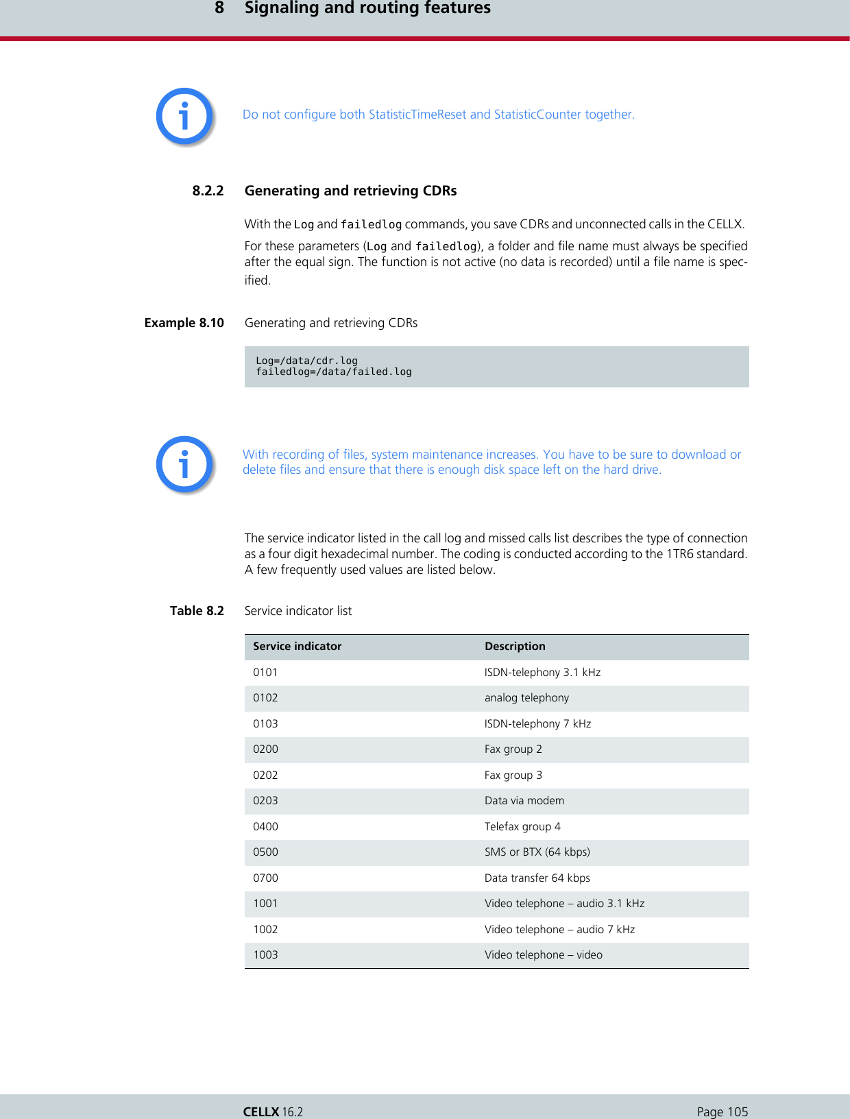
![8 Signaling and routing featuresPage 106CELLX 16.2For detailed information on how to automatically divide the files (for example on a daily basis),please refer to the Chapter 5.2.1.2 Log files.8.2.2.1 Call logThe following entry in the pabx.cfg configuration file activates the capability to generateCDRs in the CELLX:Log=/data/cdr.logThe cdr.log file is stored in the data directory. New entries are always added to the end of thefile. The file is open only during editing. Each line represents an outgoing call with the following information separated by commas:Table 8.3 Call log entries Column Description0Version1Start time (format DD.MM.YY-hh.mm.ss)2End time (format DD.MM.YY-hh.mm.ss)3Source. The following format applies: [node number:automatically set internal channel number]4Destination. The following format applies: [node number:automatically set in-ternal channel number]5IMSI6IP logging signaling: RTP7Audio codec used8Frame size9Service indicator (please see Chapter 8.2.2 Generating and retrieving CDRs)10 Call duration11 Cause values12 Charge from the public line (in units)13 Charge generated from the system (in units)14 Cell ID15 RSSI](https://usermanual.wiki/Teles-Informationstechnologien/CDMA32VOIPUS/User-Guide-1599912-Page-108.png)
![8 Signaling and routing featuresPage 107CELLX 16.2Sample log fileThe example below shows a sample log file.Differentiating between ports in the same trunk groupTo differentiate between ports with the same number in the CDRs, a specific node numbermust be defined. You can expand the subscriber configuration line with the keywordNODE[<num>] for this purpose. <num> can be a string of between 1 and 15 characters:Subscriber<xx>=... NODE[<num>]In the below formula, <num> consists of a four-digit number that is included in the CDR.Example 8.11 Sample log fileV1,25.11.09-10:16:20,25.11.09-10:16:27,[0000:01]9,[0006:01]111,123456789123451,,,,0102,7,1f,0,,3663,10V1,25.11.09-10:35:16,25.11.09-10:35:26,[0000:01]9,[0004:01]111,123456789123452,,,,0102,10,1f,0,3,38922,14V1,25.11.09-10:38:30,25.11.09-10:38:41,[0000:01]9,[0004:01]111,123456789123453,,,,0102,11,90,0,3,38922,14Example 8.12 Differentiating between ports in the same trunk group (CDR entry)V1,25.11.09-10:16:20,25.11.09-10:16:27,[0000:01]9,[0006:01]111,123456789123451,,,,0102,7,1f,0,,3663,10](https://usermanual.wiki/Teles-Informationstechnologien/CDMA32VOIPUS/User-Guide-1599912-Page-109.png)
![8 Signaling and routing featuresPage 108CELLX 16.2The following example shows the pabx.cfg configuration file changed according to the for-mula.Differentiating between SIM cardsThe CDR can contain the IMSI (International Mobile Subscriber Identity), which identifies eachSIM card used.Example 8.13 Differentiating between ports in the same trunk group (pabx.cfg entry)...Subscriber00=TRANSPARENT ROUTER GSM[0000,00000,<SMSC>,1,1,1,SIM24] CHADDR ALARM NEXT NODE[0001]Subscriber01=TRANSPARENT ROUTER GSM[0000,00000,<SMSC>,1,1,1,SIM24] CHADDR ALARM NEXT NODE[0002]Subscriber02=TRANSPARENT ROUTER GSM[0000,00000,<SMSC>,1,1,1,SIM24] CHADDR ALARM NEXT NODE[0003]Subscriber03=TRANSPARENT ROUTER GSM[0000,00000,<SMSC>,1,1,1,SIM24] CHADDR ALARM NEXT NODE[0004]Subscriber04=TRANSPARENT ROUTER GSM[0000,00000,<SMSC>,1,1,1,SIM24] CHADDR ALARM NEXT NODE[0005]Subscriber05=TRANSPARENT ROUTER GSM[0000,00000,<SMSC>,1,1,1,SIM24] CHADDR ALARM NEXT NODE[0006]Subscriber06=TRANSPARENT ROUTER GSM[0000,00000,<SMSC>,1,1,1,SIM24] CHADDR ALARM NEXT NODE[0007]Subscriber07=TRANSPARENT ROUTER GSM[0000,00000,<SMSC>,1,1,1,SIM24] CHADDR ALARM NEXT NODE[0008]Subscriber08=TRANSPARENT ROUTER GSM[0000,00000,<SMSC>,1,1,1,SIM24] CHADDR ALARM NEXT NODE[0009]Subscriber09=TRANSPARENT ROUTER GSM[0000,00000,<SMSC>,1,1,1,SIM24] CHADDR ALARM NEXT NODE[0010]Subscriber10=TRANSPARENT ROUTER GSM[0000,00000,<SMSC>,1,1,1,SIM24] CHADDR ALARM NEXT NODE[0011]Subscriber11=TRANSPARENT ROUTER GSM[0000,00000,<SMSC>,1,1,1,SIM24] CHADDR ALARM NEXT NODE[0012]Subscriber12=TRANSPARENT ROUTER GSM[0000,00000,<SMSC>,1,1,1,SIM24] CHADDR ALARM NEXT NODE[0013]Subscriber13=TRANSPARENT ROUTER GSM[0000,00000,<SMSC>,1,1,1,SIM24] CHADDR ALARM NEXT NODE[0014]Subscriber14=TRANSPARENT ROUTER GSM[0000,00000,<SMSC>,1,1,1,SIM24] CHADDR ALARM NEXT NODE[0015]Subscriber15=TRANSPARENT ROUTER GSM[0000,00000,<SMSC>,1,1,1,SIM24] CHADDR ALARM NEXT NODE[0016]...Example 8.14 Differentiating between SIM cards (CDR entry)V1,25.11.09-10:35:16,25.11.09-10:35:26,[0000:01]9,[0004:01]111,123456789123451,,,,0102,10,1f,0,3,38922,14](https://usermanual.wiki/Teles-Informationstechnologien/CDMA32VOIPUS/User-Guide-1599912-Page-110.png)
![8 Signaling and routing featuresPage 109CELLX 16.2The following example shows the pabx.cfg configuration file changed according to the for-mula.Activating peer data for VoIP callsTo generate a VoIP-call CDR entry that includes IP addresses for the remote device’s signalingand voice data, audio codec and frame size, the entry VoipIpLogging=Yes must be includedin the VoIP profile. If the entry also contains the mobile controller’s IMSI, it will appear beforethe IP addresses.Example 8.15 Differentiating between SIM cards (pabx.cfg entry)...Subscriber00=TRANSPARENT ROUTER GSM[0000,00000,<SMSC>,1,1,1,IMSI,SIM24] CHADDR ALARM NEXTSubscriber01=TRANSPARENT ROUTER GSM[0000,00000,<SMSC>,1,1,1,IMSI,SIM24] CHADDR ALARM NEXTSubscriber02=TRANSPARENT ROUTER GSM[0000,00000,<SMSC>,1,1,1,IMSI,SIM24] CHADDR ALARM NEXTSubscriber03=TRANSPARENT ROUTER GSM[0000,00000,<SMSC>,1,1,1,IMSI,SIM24] CHADDR ALARM NEXTSubscriber04=TRANSPARENT ROUTER GSM[0000,00000,<SMSC>,1,1,1,IMSI,SIM24] CHADDR ALARM NEXTSubscriber05=TRANSPARENT ROUTER GSM[0000,00000,<SMSC>,1,1,1,IMSI,SIM24] CHADDR ALARM NEXTSubscriber06=TRANSPARENT ROUTER GSM[0000,00000,<SMSC>,1,1,1,IMSI,SIM24] CHADDR ALARM NEXTSubscriber07=TRANSPARENT ROUTER GSM[0000,00000,<SMSC>,1,1,1,IMSI,SIM24] CHADDR ALARM NEXTSubscriber08=TRANSPARENT ROUTER GSM[0000,00000,<SMSC>,1,1,1,IMSI,SIM24] CHADDR ALARM NEXTSubscriber09=TRANSPARENT ROUTER GSM[0000,00000,<SMSC>,1,1,1,IMSI,SIM24] CHADDR ALARM NEXTSubscriber10=TRANSPARENT ROUTER GSM[0000,00000,<SMSC>,1,1,1,IMSI,SIM24] CHADDR ALARM NEXTSubscriber11=TRANSPARENT ROUTER GSM[0000,00000,<SMSC>,1,1,1,IMSI,SIM24] CHADDR ALARM NEXTSubscriber12=TRANSPARENT ROUTER GSM[0000,00000,<SMSC>,1,1,1,IMSI,SIM24] CHADDR ALARM NEXTSubscriber13=TRANSPARENT ROUTER GSM[0000,00000,<SMSC>,1,1,1,IMSI,SIM24] CHADDR ALARM NEXTSubscriber14=TRANSPARENT ROUTER GSM[0000,00000,<SMSC>,1,1,1,IMSI,SIM24] CHADDR ALARM NEXT...If you remove the keyword IMSI from the pabx.cfg, you must restart the system.ii](https://usermanual.wiki/Teles-Informationstechnologien/CDMA32VOIPUS/User-Guide-1599912-Page-111.png)
![8 Signaling and routing featuresPage 110CELLX 16.2The following entry shows the route.cfg configuration file changed according to the for-mula.The following CDR entry includes IP addresses for signaling and voice data, audio codec andframe size.CDRs for callback and two stage callsIn the case of CDR entries for Two stage dialing/Callback calls, the beginning and endingtimes for the first call leg is always used as the call time. The call time in seconds appears firstfor the first leg, followed by a slash and the connection time for the second leg.Specific cause valuesThe CELLX will generate cause values that represent an event, such as exceeding a definedlimit.Example 8.16 Activating peer data for VoIP calls (route.cfg entry)[Voip:DF]VoipDirection=IOVoipPeerAddress=192.168.0.2VoipIpMask=0xffffffffVoipCompression=g729 t38VoipMaxChan=30VoipSilenceSuppression=Yes VoipSignalling=0VoipTxM=4VoipIPLogging=YesExample 8.17 Activating peer data for VoIP calls (CDR entry)V1,24.11.09-16:52:20,24.11.09-16:52:22,[0008:01]401419,[0006:01]IN777,123456789123451,172.20.25.103:172.20.25.103,G711a,20,0101,2,10,0,,34193,11Example 8.18 CDR entry for callback and two stage callsV1,24.11.09-17:15:29,24.11.09-17:15:57,[0002:01]CB,[0008:01]DLA,,172.20.25.103:172.20.25.103,G711a,20,0102,28/3,90,0,,,Table 8.4 Specific cause valuesCause value Description0a One of the following limits has been reached: Unit limit defined in the port’s subscriber line0b Maximum call duration assigned via vGATE has been reached.0c Maximum call duration based on mapping entry settings has been reached.](https://usermanual.wiki/Teles-Informationstechnologien/CDMA32VOIPUS/User-Guide-1599912-Page-112.png)
![8 Signaling and routing featuresPage 111CELLX 16.28.2.2.2 Missed calls listAll incoming calls that are not connected can be recorded in a list to facilitate return calls.Recording is activated using the failedlog=<name> entry in the pabx.cfg. Specify a filename, for example failedlog=failed.log. Once this setting is made, recording begins at once.Each line represents an unaccepted incoming call with the following information separatedby commas.0d Maximum number of minutes per SIM assignment via vGATE has been reached.10, 1f Normal call termination (disconnected by calling party).To avoid sending these values as the reason for call teardown, translate the cause values to standard values Chapter 8.14 Changing cause values.Table 8.4 Specific cause valuesCause value DescriptioniiTable 8.5 Failed log entries Column Description0Version1Start time (format DD.MM.YY-hh.mm.ss)2Source. The following format applies: [node number:automatically set internal channel number]3Destination. The following format applies: [node number:automatically set inter-nal channel number]4IMSI5IP logging signaling: RTP6Audio codec used7Frame size8Service indicator (please see Chapter 8.2.2 Generating and retrieving CDRs)9Cause values10 Call duration (if the call does not result in an Alerting, the entry will be -1)11 Number of call attempts12 Cell ID13 RSSI](https://usermanual.wiki/Teles-Informationstechnologien/CDMA32VOIPUS/User-Guide-1599912-Page-113.png)
![8 Signaling and routing featuresPage 112CELLX 16.2The reason the connection could not be established is specified using DSS1 codes:91 – (user busy)ff – call not answered (disconnected by calling party)When callback with DTMF is configured and no connection is established to the B subscriber,an entry recording the A subscriber’s connection time is generated in the failed.log file.The CDR contains the IP addresses for signaling and voice data. The first IP address is the sig-naling address and the second one is the RTP address.The IMSI is written behind the IP ad-dresses if the keyword IMSI is defined in the pabx.cfg.In the case of missed-call entries for Two stage dialing/Callback calls, dur is the connectiontime for the first leg.8.2.2.3 Sending CDRs via e-mailWith an appropriate configuration, you can send corresponding CDRs of outgoing and in-coming calls as e-mail. Bear in mind that the mail server must be configured in the [Mail] sec-tion of the pabx.cfg, as described in Chapter 5.2.2 SMTP-client configuration. The sender isgiven as cdr and the system’s name appears in the subject box. The text box contains the CDRExample 8.19 Failed.log fileV1,24.11.09-16:13:08,[0006:01]IN,[0008:01]GSM,123456789123456,,,,0101,92,-1,1,34193,9V1,24.11.09-16:33:34,[0006:01]IN,[0008:01]GSM,123456789123456,,,,0101,92,-1,1,34193,12V1,24.11.09-16:35:19,[0006:01]IN,[0008:01]GSM,123456789123456,,,,0101,92,-1,1,34193,11V1,24.11.09-16:35:59,[0006:01]IN,[0008:01]GSM,123456789123456,,,,0101,92,-1,1,34193,11V1,24.11.09-16:37:29,[0006:01]IN,[0008:01]GSM,123456789123456,,,,0101,92,-1,1,34193,11V1,24.11.09-16:39:17,[0006:01]IN,[0008:01]GSM,123456789123456,,,,0101,ff,7,1,34193,11Example 8.20 Failed.log entry 1V1,24.11.09-16:39:17,[0006:01]IN,[0008:01]GSM,123456789123456,,,,0101,ff,7,1,34193,11Example 8.21 Failed.log entry 2V1,24.11.09-16:52:20,24.11.09-16:52:22,[0008:01]401419,[0006:01]IN777,262032441017556,172.20.25.103:172.20.25.103,G711a,20,0101,2,10,0,,34193,11Example 8.22 Failed.log entry 3V1,25.11.09-14:11:10,[0002:01]CB,DLA,,,,,0102,11,14,1,,](https://usermanual.wiki/Teles-Informationstechnologien/CDMA32VOIPUS/User-Guide-1599912-Page-114.png)
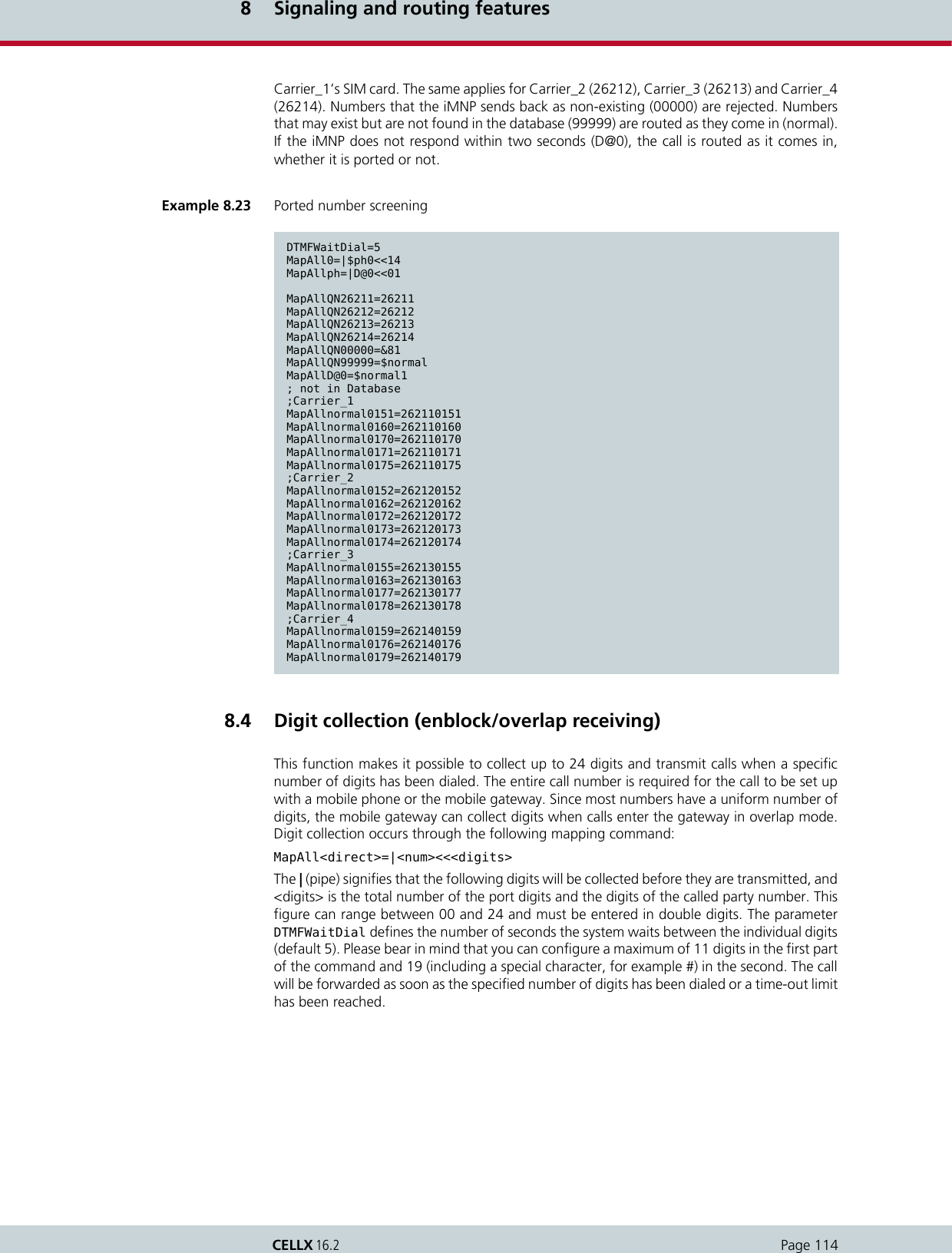
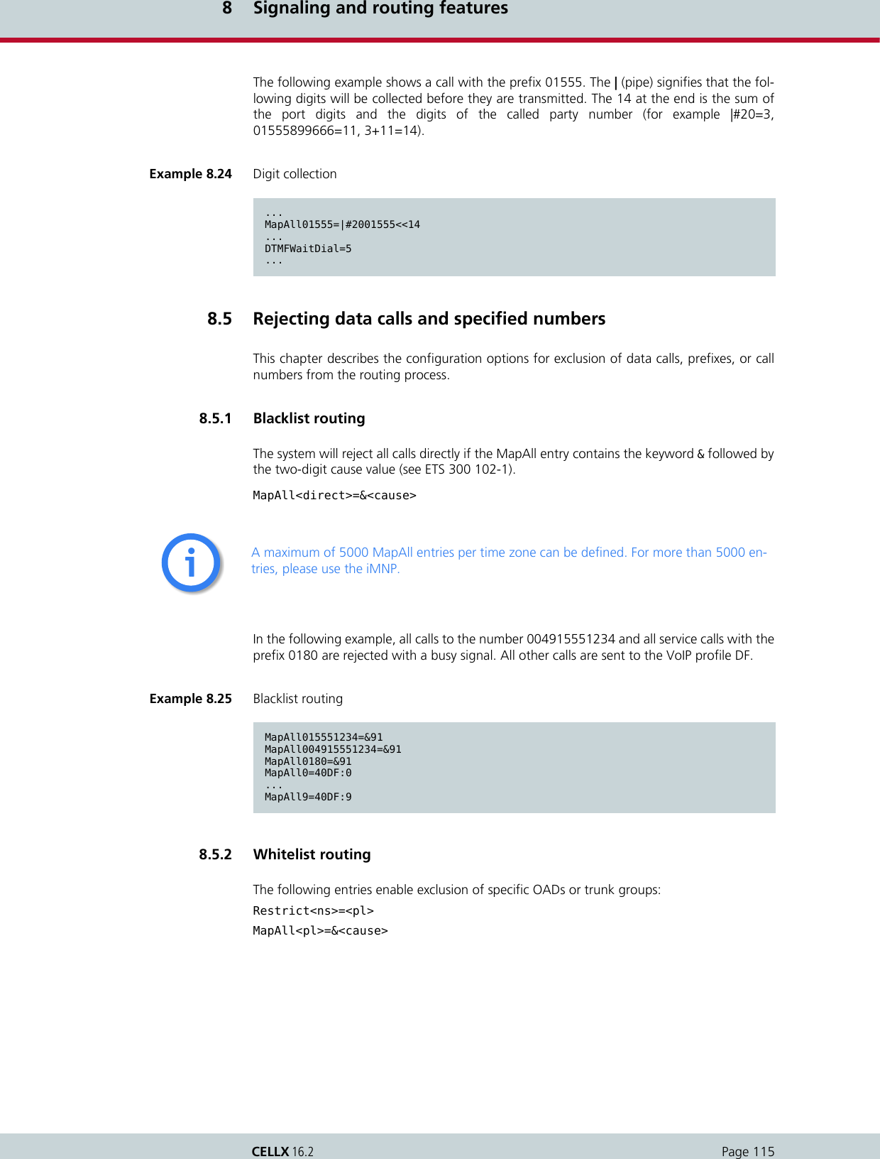
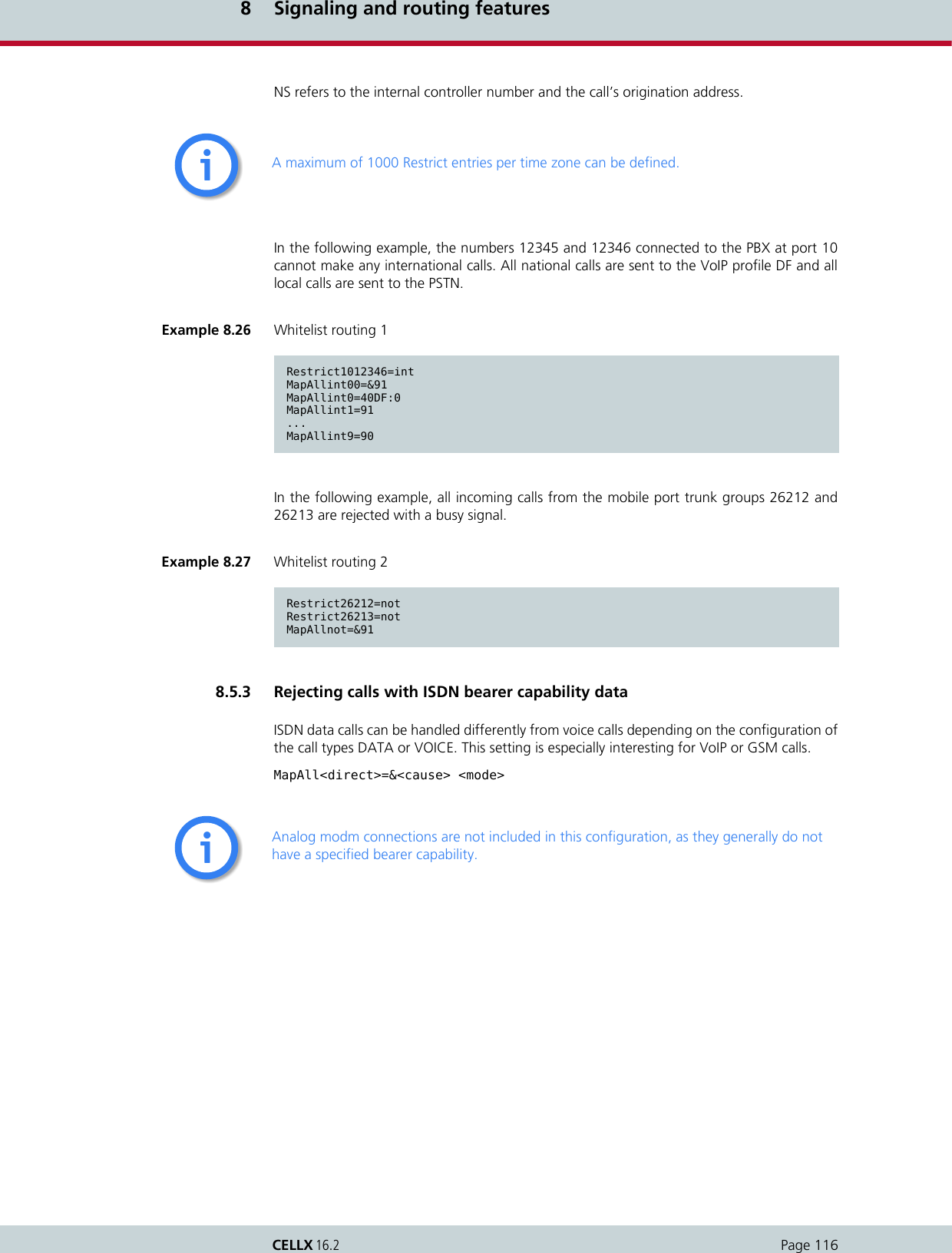
![8 Signaling and routing featuresPage 117CELLX 16.2In the following example, all ISDN data calls are rejected with the cause value AA (switchingequipment congestion). All calls with the prefix 0170 are routed to the mobile trunk group26211 and all other calls are routed through VoIP.8.5.4 Specific routing of data calls via VoIPIn the ISDN network, data calls have a special service type. When an ISDN PBX is connectedto a VoIP network, it must continue to work without any problems (for example PBX remotemaintenance calls or ISDN terminal adapter). In the case of VoIP, a specific RTP payload typeis used: trp, ccd or gnx64.In the following example, two VoIP profiles are configured, so that all calls are routed, regard-less of whether they are data calls or voice over IP calls. The first one is for outgoing voice callsand all calls from VoIP to ISDN. The second profile is exclusively for outgoing data calls, sothat signaling consists solely of clear mode in SDP.8.6 CLIP and CLIR8.6.1 Routing CLIP and CLIR callsThis function allows you to route calls with Calling Line Identification Presentation (CLIP) dif-ferently from calls with Calling Line Identification Restriction (CLIR). For example, all CLIP callscan be rejected, so that only calls that do not present the calling number or calls without acalling party number (for example analog) are transmitted through the CELLX.Example 8.28 Rejecting calls with ISDN bearer capability dataMapAll0=&aa DATA...MapAll9=&aa DATA... MapAll0170=262110170MapAll0=40DF:0...MapAll9=40DF:9Example 8.29MapAll0=40DATA:0 DATA...MapAll9=40DATA:9 DATAMapAll0=|40DF:0<<24...MapAll9=|40DF:9<<24Restrict40=InMapAllIn=10[Voip:DF]VoipDirection=IO...VoipCompression=g711a g729 trp t38...[Voip:DATA]VoipDirection=Out...VoipCompression=trpVoipECE=No...](https://usermanual.wiki/Teles-Informationstechnologien/CDMA32VOIPUS/User-Guide-1599912-Page-119.png)
![8 Signaling and routing featuresPage 118CELLX 16.2Use the following configuration to define the various routing methods.InsertCLIR=On activates this mode. 01 is the service indicator for telephony (analog and ISDN)and is used to differentiate these calls from remote administration calls. Restrict9=OK 01means that all telephony calls without a calling number are put through. Restrict|9=OK 01means that all CLIR telephony calls are put through. Restrict90=FAIL 01 means that all CLIPtelephony calls are rejected with No Channel Available as rejection cause when they aremapped to MapInFAIL=&aa. 8.6.2 Routing calls without CLIRUse this function to bypass CLIR for calls through the defined mobile port. The following con-figuration in pabx.cfg activates this function.8.6.2.1 Setting CLIRSetting a hash (#) in front of a call number makes it possible to suppress the presentation ofthe origination number of calls regardless of how the call comes into the system.The following syntax is used: MapAll<num>=#<port><num>.The following example shows an appropriate configuration. With this entry, all calls begin-ning with 00491555 are sent to the port with the address 22 and the presentation of thenumber is restricted.Example 8.30 Routing CLIP and CLIR calls...InsertCLIR=On...Restrict9=OK 01Restrict|9=OK 01Restrict90=FAIL 01...MapInOK00491555=2200491555MapInFAIL=&aa...Example 8.31 Routing calls without CLIRSubscriber<xx>=...GSM[...,!CLIR]...When this function is configured, the SIM’s telephone number (and not originating telephone) is always transmitted to the B subscriber.iiExample 8.32 Setting CLIRMapAll00491555=#2200491555](https://usermanual.wiki/Teles-Informationstechnologien/CDMA32VOIPUS/User-Guide-1599912-Page-120.png)
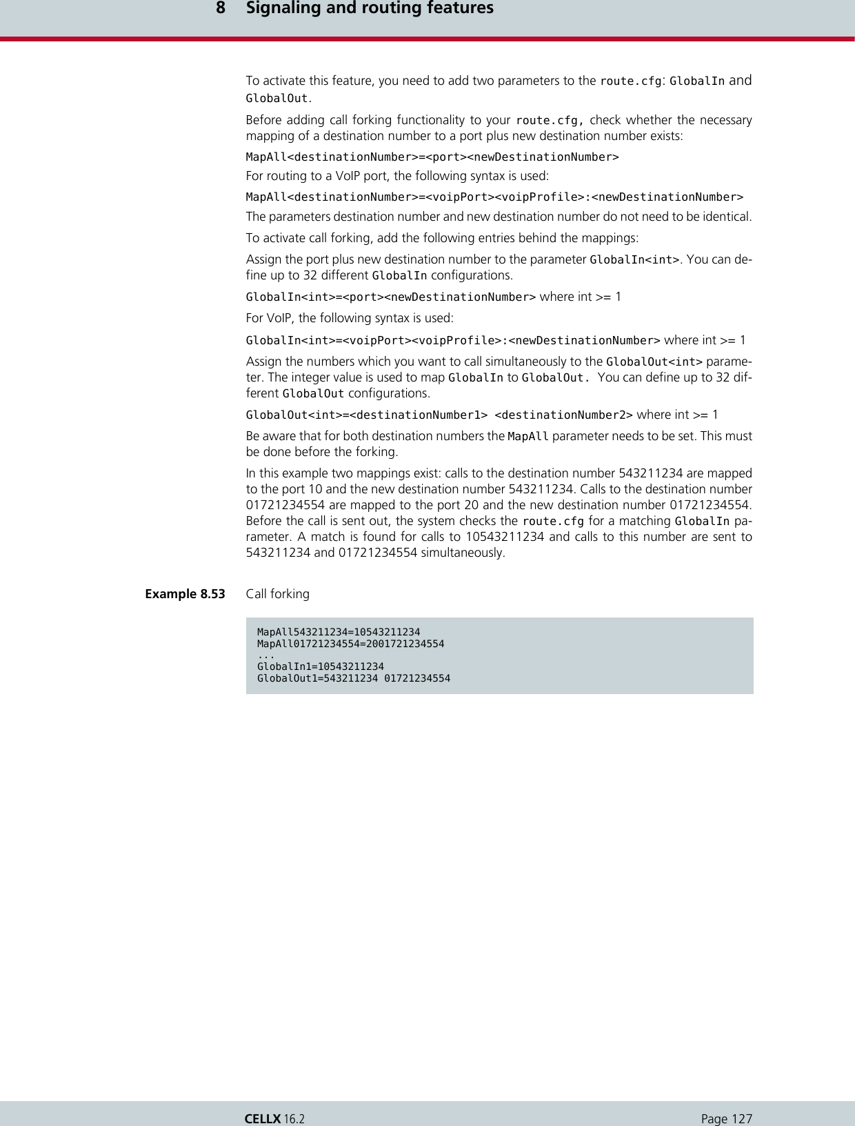
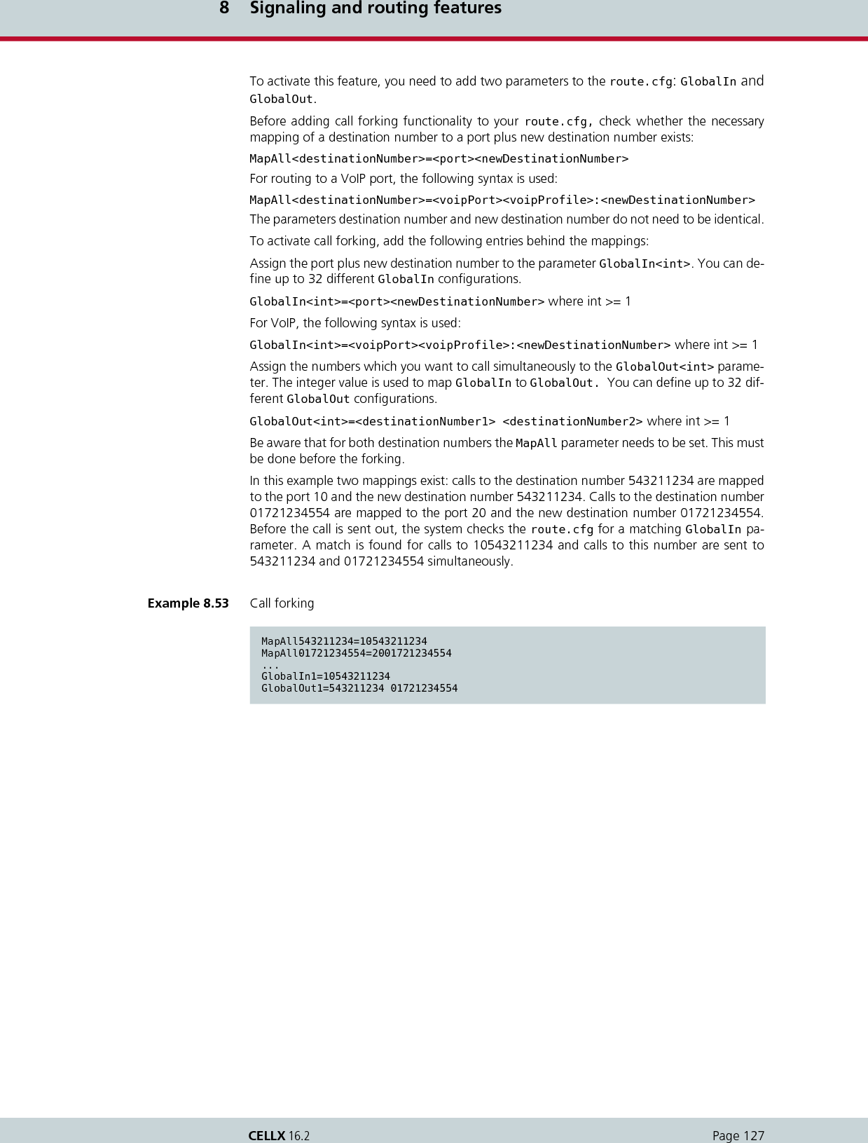
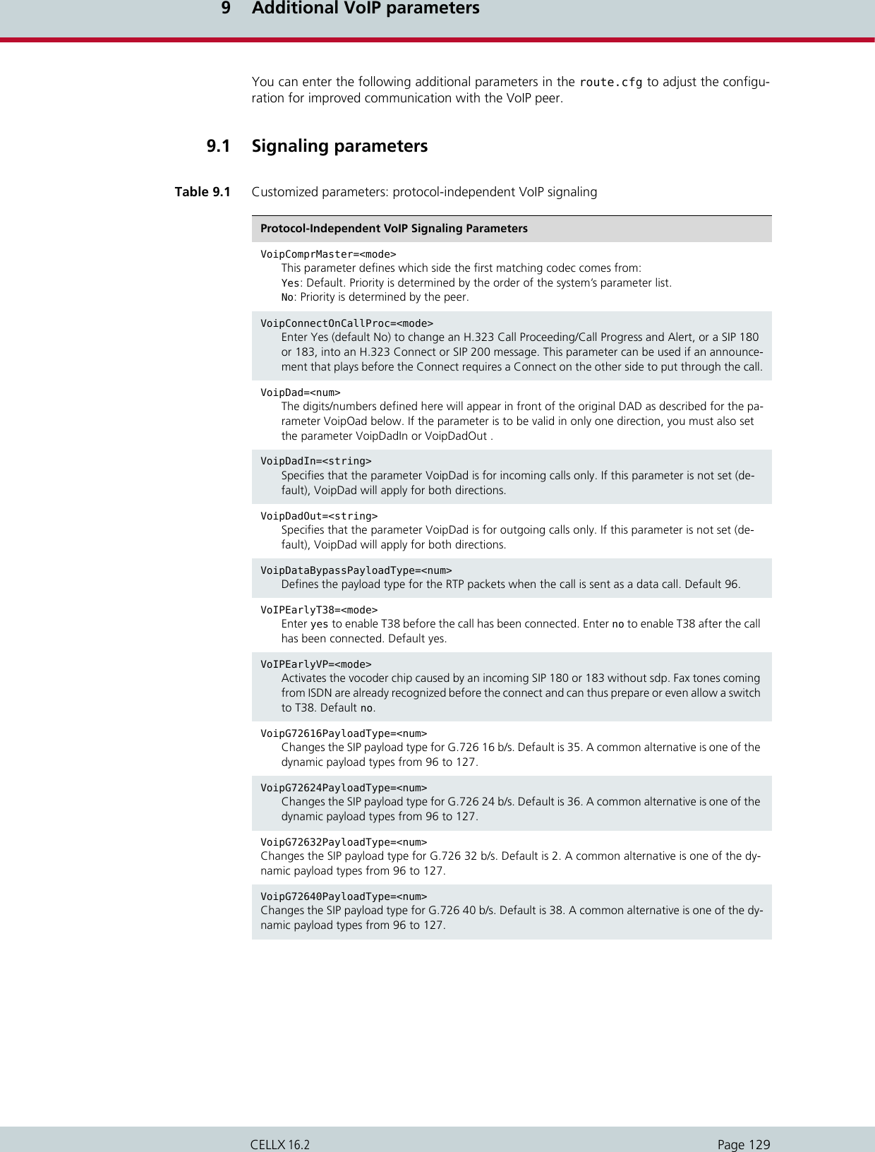
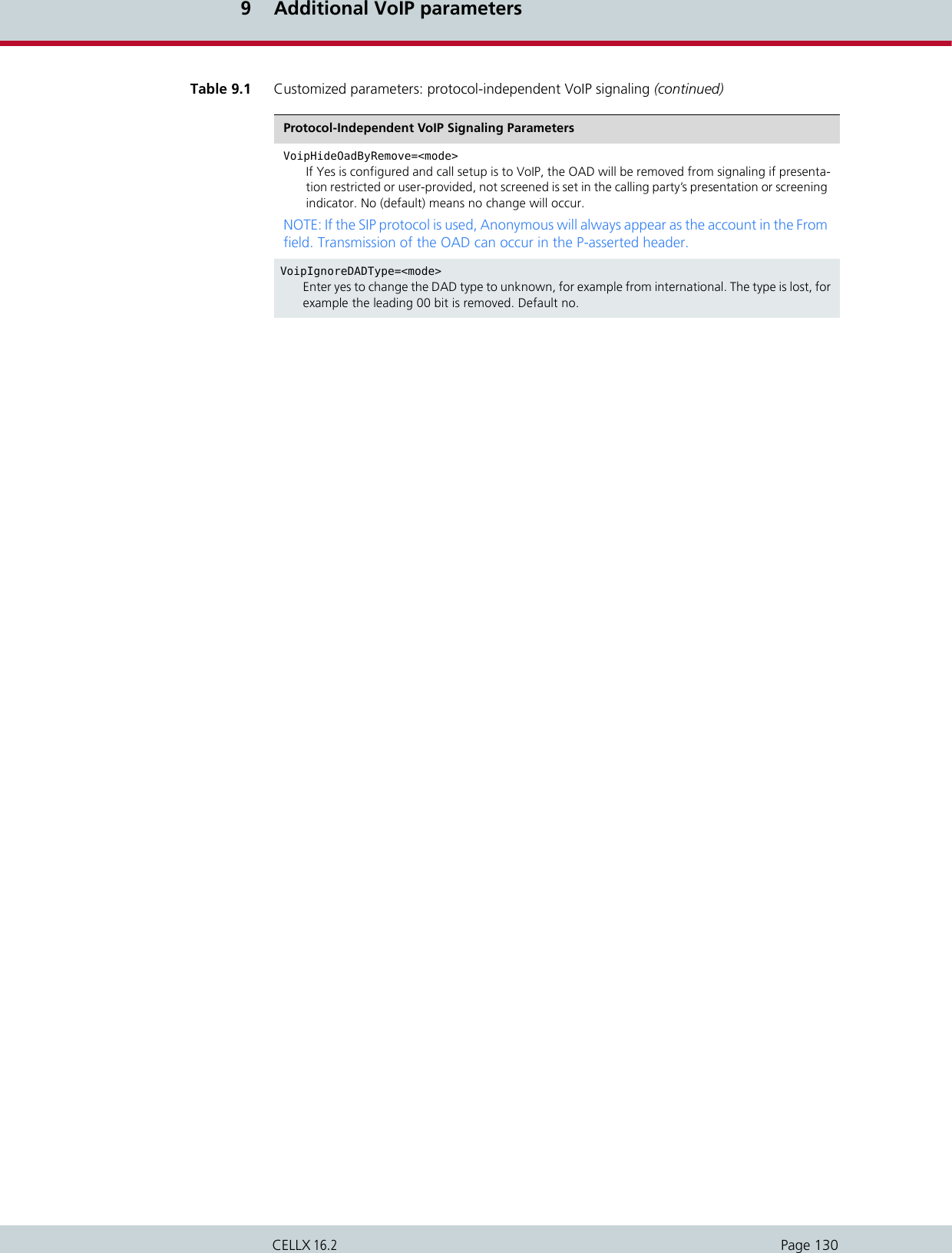
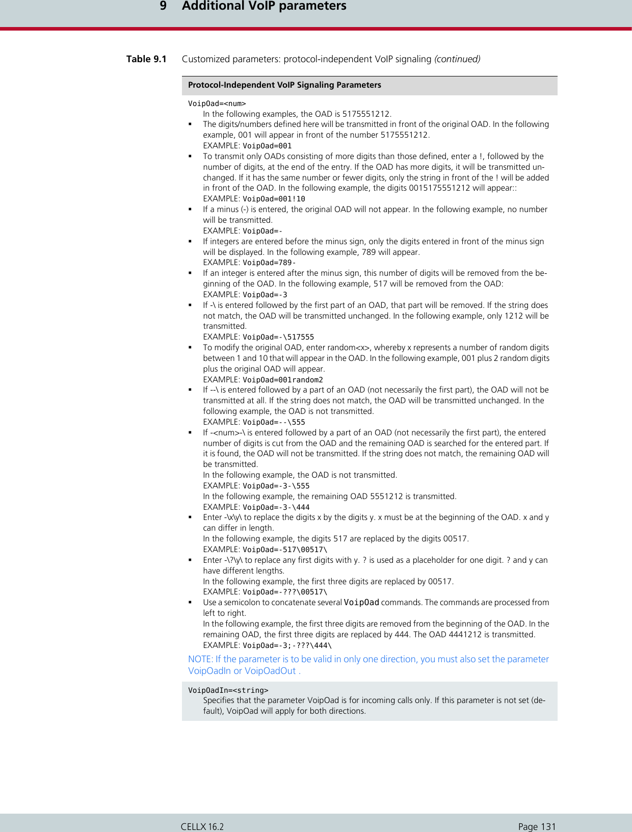
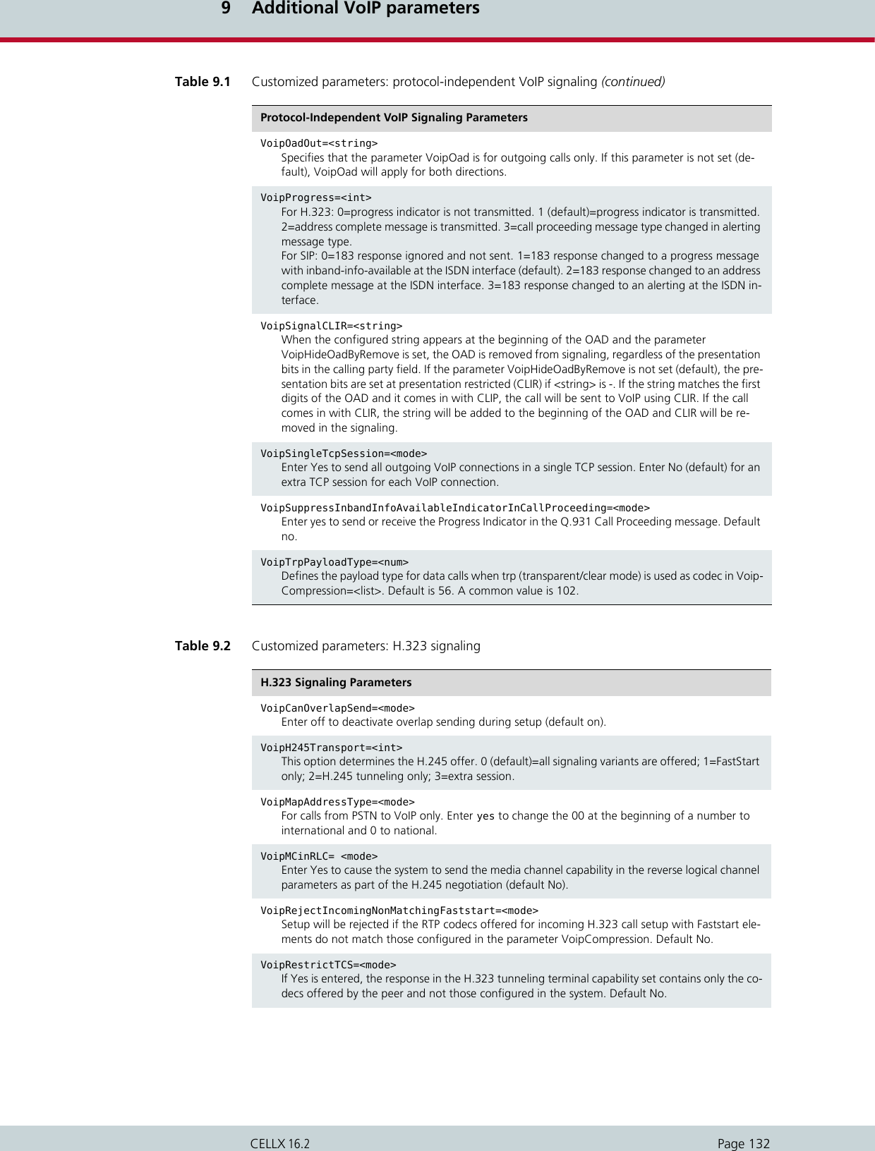
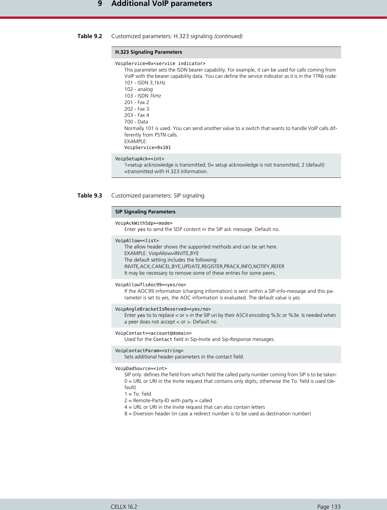
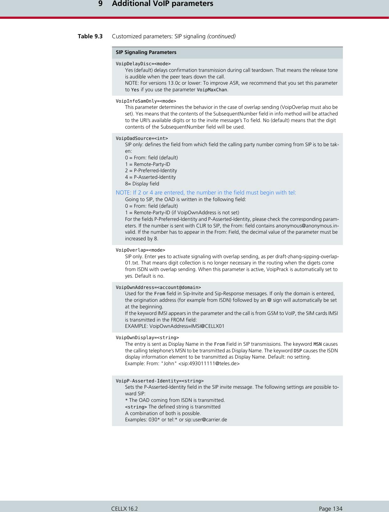
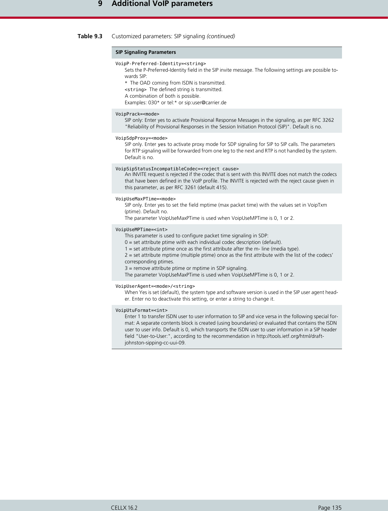
![9 Additional VoIP parametersPage 136CELLX 16.29.2 Registrar parametersThe following parameters can be used in the VoIP profile when the SIP agent wants to registerwith the CELLX. The following example creates an account for a user agent with the username 130 and pass-word test130. Authentication occurs with the procedure www.Table 9.4 Customized parameters: location server Location Server ParametersVoipAuth=<mode>Defines the authentication procedure www (default) or proxy.VoipExpires=<sec>Defines the maximum number of seconds the agent’s registration applies (default 3600).VoipOwnPwd=<string>Defines the password the agent uses to register.VoipOwnUser=<string>Defines the username the agent uses to register.Example 9.1 Registrar parametersMapAll130=40U1:130[Voip:U1]VoipDirection=IOVoipIpMask=0x00000000VoipOwnUser=130VoipOwnPwd=test130VoipExpires=300VoipAuth=wwwVoipCompression=g711a g711u g729 g729a g729b g729ab VoipSilenceSuppression=noVoipSignalling=1VoipMaxChan=8VoipTxM=2VoipDtmfTransport=0VoipRFC2833PayloadType=101VoipMediaWaitForConnect=Tone](https://usermanual.wiki/Teles-Informationstechnologien/CDMA32VOIPUS/User-Guide-1599912-Page-138.png)
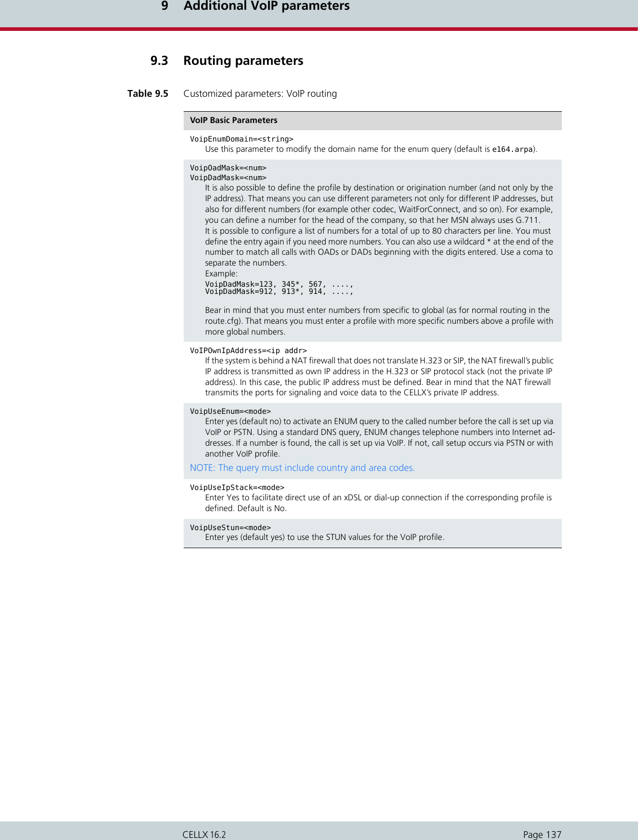
![9 Additional VoIP parametersPage 138CELLX 16.29.4 Quality parametersTable 9.6 Customized parameters: VoIP quality VoIP Quality ParametersSigTos=<num>Enter a value between 0 and 255 (default is 0) to set the TOS (type of service) field in the SIP/SIPS packet IP header. Possible values are described in Table 9.7. If your IP network uses differentiated services, you can also define the DSCP (differentiated services codepoint) for the SIP/SIPS packets. The DSCP is the first six bits in the TOS octet.NOTE: SigTos is set in the [System] section of the pabx.cfg file.VoipAGC=<x y z>This parameter allows automatic gain control of input signals from PSTN or IP. Enabling this fea-ture compensates for near-far gain differences:x - direction (0 for signals from TDM, 1 for signals from IP)y - gain slope (controls gain changing ratio in -dBm/sec, values 0 to 31, default 0)z - target energy (determines attempted signal energy value in -dBm, values 0 to 63, default 19Gain Slope:0 - 00.25dB 1 - 00.50dB 2 - 00.75dB3 - 01.00dB 4 - 01.25dB 5 - 01.50dB6 - 01.75dB 7 - 02.00dB 8 - 02.50dB9 - 03.00dB 10 - 03.50dB 11 - 04.00dB12 - 04.50dB 13 - 05.00dB 14 - 05.50dB15 - 06.00dB 16 - 07.00dB 17 - 08.00dB18 - 09.00dB 19 - 10.00dB 20 - 11.00dB21 - 12.00dB 22 - 13.00dB 23 - 14.00dB24 - 15.00dB 25 - 20.00dB 26 - 25.00dB27 - 30.00dB 28 - 35.00dB 29 - 40.00dB30 - 50.00dB 31 - 70.00dBVoipAutoRtpAddr=<mode>Some application scenarios require automatic RTP IP address and port detection for VoIP calls, for example if a firewall or NAT changes the IP address of incoming RTP data. Enter Yes to activate automatic detection. When No is set, RTP packets sources other than those processed are reject-ed. Default No. VoipBandwidthRestriction=<mode>Enter Yes to include the VoIP profile in traffic shaping. Default is No. For a description of the func-tionality, please refer to VoipMaximumBandwidth in Table 5.18.VoipBrokenDetectionTimeout=<ms>When this parameter is set, the system processes an interruption in the transmission of RTP/RTCP data in the VoIP connection following the set number of milliseconds (default 0). This parameter is necessary to set up an IntraSTAR call immediately when the IP connection is disrupted. Bear in mind that VoipSilenceSuppression=No must appear in the VoIP profile. VoipCallGroup=<name>All outgoing VoIP calls for VoIP profiles with the same VoipCallGroup name are distributed cycli-cally to these profiles.VoipConnBrokenTimeout=<sec>An entry is generated in the protocol.log file and the connection is terminated after a connection broken exists for the number of seconds entered (default 300). If 0 is entered, no entry will be generated and the connection will not be terminated.VoipDJBufMaxDelay=<count>Enter a value in milliseconds (0-320) to set a maximum jitter buffer limit (default 150). For fax transmission (t.38) it is fixed to 200ms.NOTE: VoipDJBufMaxDelay must be greater than VoipDJBufMinDelay.](https://usermanual.wiki/Teles-Informationstechnologien/CDMA32VOIPUS/User-Guide-1599912-Page-140.png)
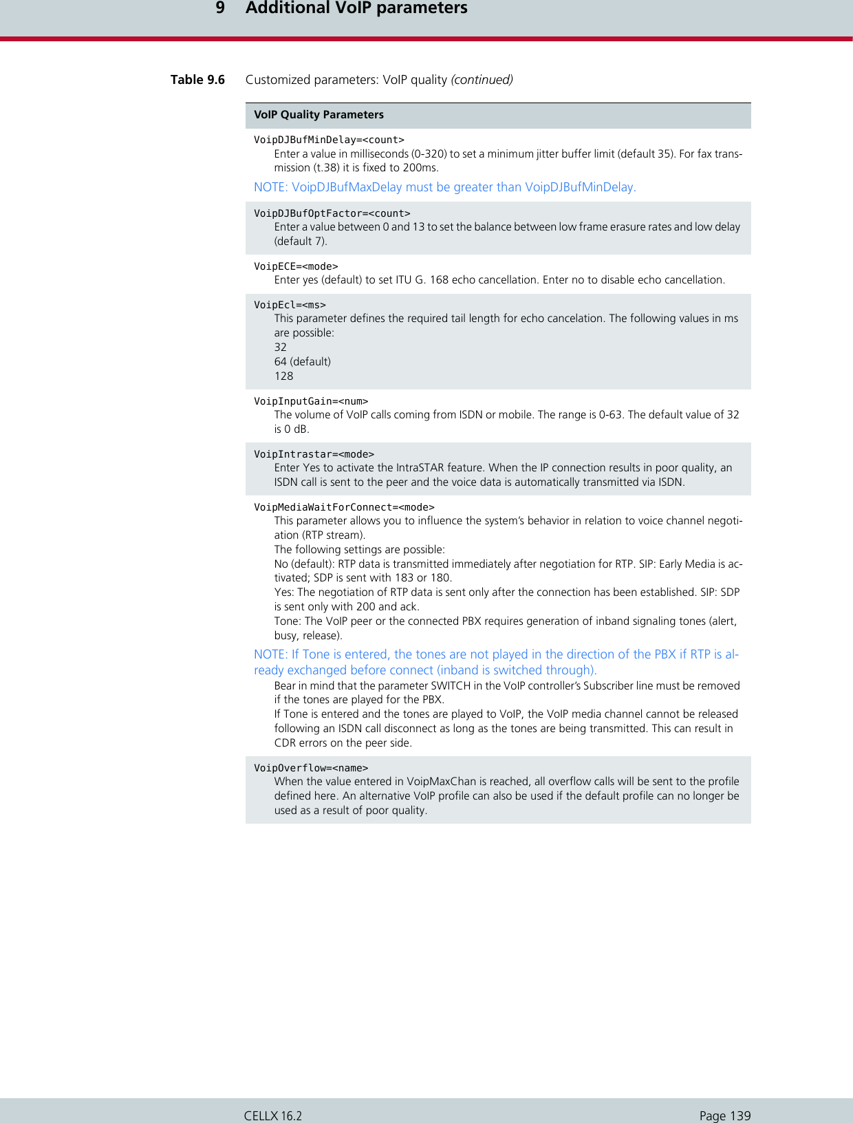
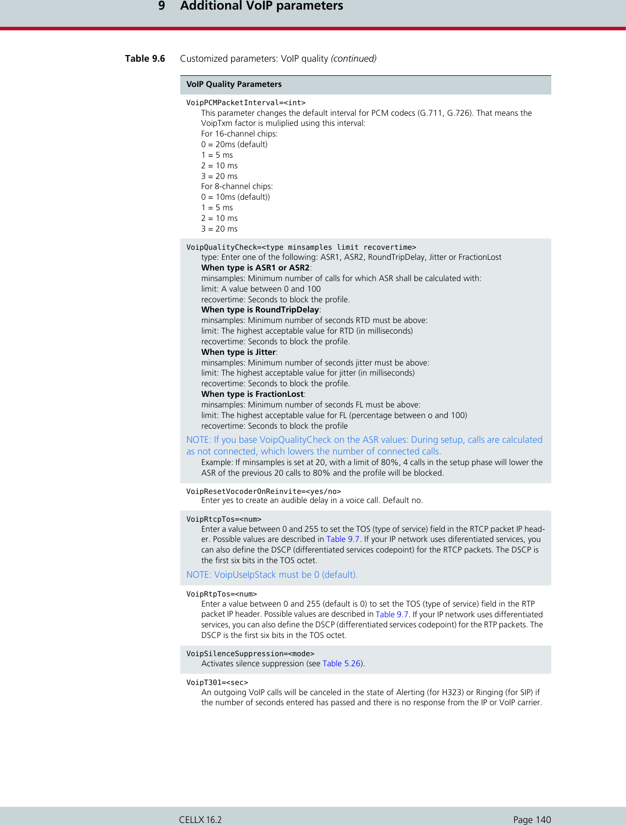
![9 Additional VoIP parametersPage 141CELLX 16.2The following specifications for Quality of Service correspond with RFC791 and RFC1349.VoipT303=<sec>If this parameter is entered in a SIP profile, transmission of the INVITE is canceled after the number of seconds entered has passed (default 10). The call can then be redirected, for example to PSTN. This improves the reliability of the system when an IP or VoIP carrier’s service fails.EXAMPLE:Redirect340DF:=AMapAllA=9[Voip:DF].....VoipT303=5VoipT304=<sec>An outgoing VoIP calls will be canceled in the state of Setup Acknowledge (for H323) or Trying (for SIP) if the number of seconds entered has passed and there is no response from the IP or VoIP carrier.VoipT310=<sec>An outgoing VoIP calls will be canceled in the state of Call Proceeding (for H323) or Session Progress (for SIP) if the number of seconds entered has passed and there is no response from the IP or VoIP carrier.VoipTcpKeepAlive=<mode>Enter yes (default) to send the RoundTripDelayRequest message every 10 seconds (necessary for long calls with firewalls using TCP aging).VoipVoiceVolume=<num>The volume of VoIP calls coming from the Ethernet. The range is 0-63. The default value of 32 is 0 dB.Table 9.6 Customized parameters: VoIP quality (continued)VoIP Quality ParametersTable 9.7 Quality of service values Bit Distribution01234567Precedence TOS MBZBit Description0-2 Precedence3 TOS: 0=normal delay, 1=low delay4TOS: 0=normal throughput, 1=high throughput5 TOS: 0=normal reliability, 1=high reliability6TOS: 0=normal service, 1=minimize monetary cost7 MBZ: must be 0 (currently not used)Precedence Description111 Network control110 Internetwork control101 CRITIC/ECP100 Flash override](https://usermanual.wiki/Teles-Informationstechnologien/CDMA32VOIPUS/User-Guide-1599912-Page-143.png)
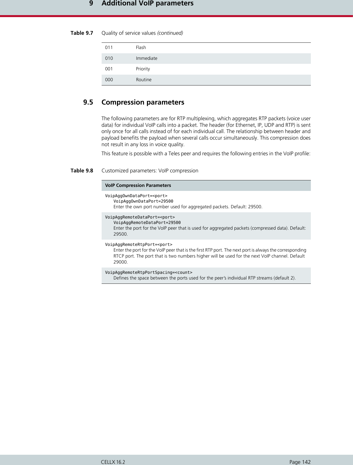
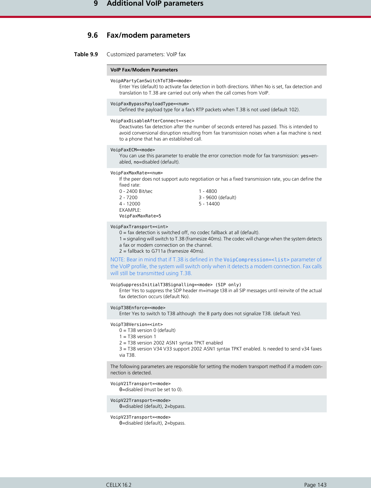

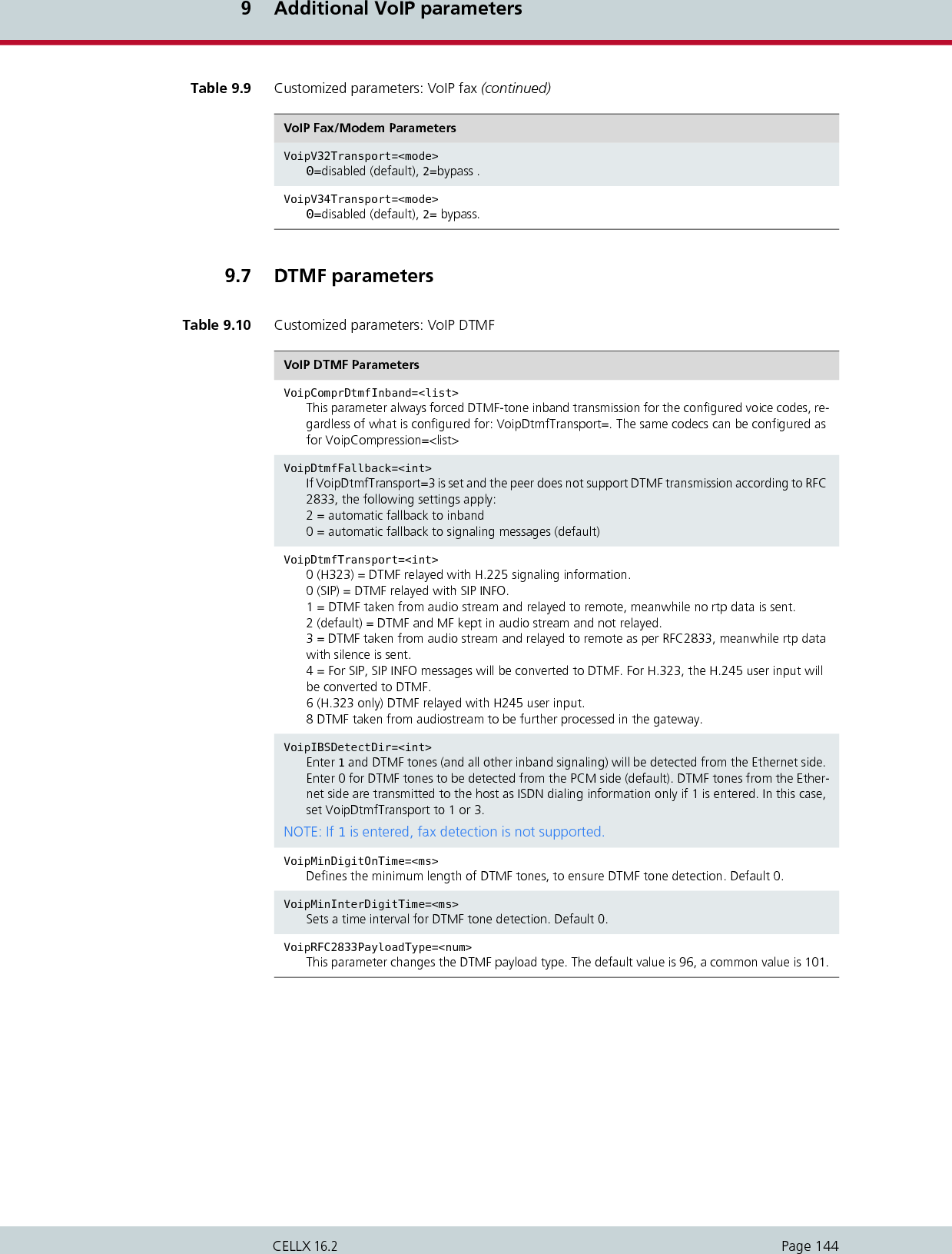
![10 System maintenance and software updatePage 146CELLX 16.210.1 Configuration errorsWhen typographical errors are made in the configuration files, an entry appears in the pro-tocol.log when the configuration is activated. This entry includes the line number and itscontents.10.2 Status and error messagesThe protocol.log file – assigned as the file for logging the protocol in the configuration file(ActionLog=file) – contains information on all activities within the system. In the example below, you can see that all activities are recorded beginning with the date andtime. If functions were activated by key combinations from terminal devices you can identifythese along with the service ID.Example 10.1 Status and error messages16.05.06-11:51:31,[990]Start STATUS - TELES.iGATE V11.7a (007f)16.05.06-12:10:57,[01A]ERR: Layer1 16.05.06-12:10:58,[000]ERR: OK 16.05.06-12:10:58,[010]ERR: OK 16.05.06-12:12:06,Remote Control from IP 192.168.1.216.05.06-12:12:06,Remote Control: OK 16.05.06-12:12:16,Activate Configuration System 16.05.06-12:16:26,Remote Control Terminated 16.05.06-14:00:00,Activate Configuration Night2 16.05.06-14:00:00,Time Switch Operation 16.05.06-18:00:00,Activate Configuration Night3 16.05.06-18:00:00,Time Switch Operation Table 10.1 Event log messages Message NMS DefinitionStatus Program[990] Start STATUS XTELES system software and sta-tus program have been started. System Start[999] System-Boot XSystem restarted by timer.[999] Remote Control: Reboot System restarted by remote ad-ministration command.Configuration ChangesActivate configuration <num> OKConfiguration <num> success-fully loaded. Initiator displayed in next line.Activate configuration <num> failed [<err>]Configuration <num> could not be loaded. Remote Control: Date & Time changedDate and/or time were changed via remote adminis-tration.](https://usermanual.wiki/Teles-Informationstechnologien/CDMA32VOIPUS/User-Guide-1599912-Page-148.png)
![10 System maintenance and software updatePage 147CELLX 16.2Time Switch Operation The configuration change was made by the timer.Remote AdministrationRemote Control from <peer>, <RemoteCode>, <service>, 0Remote administration access from number or IP address.Remote Control: OK Successful remote administra-tion access.[993]Remote Control: wrong passwordX Remote administration access was denied because of a wrong password.[994]Remote Control: wrong numberXRemote administration access was denied because the call originated from an unautho-rized number (RemoteOrigina-tion). Remote Control Terminated <start time>,<end time>, <num>, <RemoteCode>, <ser-vice>, 0Remote administration session from <num> ended. Session length is indicated by start time and end time.Errors Reported by the Status Program[<port><i>] ERR: Problem at Port <num>X A Layer 1 or Layer 2 error oc-curred on <num>.<i> indicates error type:A Layer 1 error ; Layer 2 error 0 Layer 1&2 op-erational.4 RSSI (for mo-bile only)If the error persists, a differenti-ation is possible through 'status of the ports'.If this message appears, status inquiry connections via remote administration are accepted and NMS downloads the proto-col.log file.NOTE: If the RSSI falls below the value configured in the pabx.cfg, the port will shut down automatically.Attention: No Callback-Call <num> ArrivedCallback with DTMF: the Call-back Provider <num> did not call back within approx. 20 sec.Direct Line Access with DTMF: the call was accepted but dis-connected again within x sec. (as defined by MapCallBack-WaitDisc).Table 10.1 Event log messages (continued)Message NMS Definition](https://usermanual.wiki/Teles-Informationstechnologien/CDMA32VOIPUS/User-Guide-1599912-Page-149.png)
![10 System maintenance and software updatePage 148CELLX 16.2The following options are available for monitoring the Mobile Boards’ status or the status ofeach mobile channel. You can access status information through data recorded in the proto-col.log file or in the Layer 1 column in the GATE Manager’s Port Status window.The following status and error messages appear in the protocol.log file when ALARM appearsin the VoIP port’s subscriber line: Write error Access to the disk drive on which the data is to be stored was not possible because it is set for read-only, full or be-cause of faulty hardware or software.[995] Msg-Memory > 75% XThis message appears when message memory is over 75% full.If this message appears, status inquiry connections via remote administration are accepted and NMS downloads the proto-col.log file.Table 10.1 Event log messages (continued)Message NMS DefinitionTable 10.3 Protocol log status and error messages Message DefinitionSystem Configuration (a)config: <num> duplicate profile Specified line in pabx.cfg or route.cfg contains duplicate profile.config: <num> invalid Specified line in pabx.cfg or route.cfg is invalid.config: evaluation errcode <num> Internal error.Port-Specific Entries[<port>]Unblock Port The <port> has been unblocked. This can occur via remote access for all controller types.[<port>]Block Port The <port> has been blocked. This can occur via remote access for all controller types.[<port>]Restart Port The <port> has been blocked. This can occur via remote access for all controller types. Ethernet Interface[99d]ERR: emac<num><state> The Ethernet controller’s status is checked every minute and any change in status is noted.<num> Number of the EMAC interface (0 or 1).<state> up Ethernet link is activedown Ethernet link is inactive!resolve ip-address ARP request for specified IP address failed.](https://usermanual.wiki/Teles-Informationstechnologien/CDMA32VOIPUS/User-Guide-1599912-Page-150.png)
![10 System maintenance and software updatePage 149CELLX 16.2pingcheck failed Ping to configured server failed for configured amount of time; host might reboot this port.Voice Packetizer Task (b)[<port>]ERR: OK, <count> devices The number (<count>) of DSPs were loaded dur-ing startup without errors. The first VoIP control-ler appears in [<port>].[<port>]ERR: init failed A DSP could not be loaded. This DSP or the first VoIP controller is defined in [<port>].VP: <channel> <msg> Voice-packetizer chips report fatal error on spec-ified channel, with specified message.VoIP (c)GK <name> URC Successful UnRegister from specified gatekeep-er.GK <name> GRJ <num> GatekeeperRequest was rejectedGK <name> RCF Successful RegistrationRequest (Registration-Confirm).GK <name> RRJ <num> RegistrationRequest was rejected.GK <name> ARJ <dad> <num> AdmissionRequest was rejected.GK <name> !ACF dad AdmissionRequest was not answered.GK <name> !GCF GatekeeperRequest was not answered.no profile for ipaddress Incoming VoIP call from specified IP address was rejected due to no matching VoIP profile.registrar <name>: registration done Successful registration at SIP registrar.registrar <name>: wrong auth-type <num> Registrar does not perform MD5 for authentica-tion.registrar <name>: gives no nonce Nonce missing in response from registrar (possi-ble error in registrar configuration).registrar <name>: registration forbidden Registration with specified registrar is not al-lowed.registrar <name> not answering Specified registrar does not respond.voipconn oad->dad broken Voice codec chips report broken RTP connection.voip FdInitAll failed <cause> Internal failure.voip ISDNListen failed Internal failure.voipIpSocketInit failed Internal failure.!DNS-lookup <hostname> DNS lookup for specified host name failed (DNS not activated? Missing or invalid DNS server?).message from <ip addr> not decodable H323, ASN1 packet cannot be decoded.vGATETable 10.3 Protocol log status and error messages (continued)Message Definition](https://usermanual.wiki/Teles-Informationstechnologien/CDMA32VOIPUS/User-Guide-1599912-Page-151.png)
![10 System maintenance and software updatePage 150CELLX 16.2[99]ERR: SimUnit !connect An outgoing connection to the vGATE SIM Unit could not be established. [99]ERR: ControlUnit <ip addr> !connect An outgoing connection to the vGATE Control Unit could not be established. Number Portability[99i]ERR: np !connect Connection to the iMNP could not be estab-lished. [99i]ERR: np connect <ip addr> Connection to the iMNP reestablished. System Kernel (e)task <name> suspended specified task was suspended due to internal er-ror; host might reboot this port.Mail (f)cdr !connect <ip addr> sending CDR: TCP connect to specified IP ad-dress failed.mail !connect <ip addr> sending e-mail: TCP connect to specified IP ad-dress failed.Radius (g)!DNS-lookup <hostname> DNS lookup for specified host name failed (DNS not activated? Missing or invalid DNS server?).timeout auth <ip addr> Authentication request to specified Radius server failed due to timeout.timeout acnt <ip addr> Accounting request to specified Radius server failed due to timeout.!rsp-auth <ip addr> Response authenticator from specified Radius server was invalid (wrong secret/password?).!auth <ip addr> <num> Authentication denied by specified Radius server.Configuration Errors in the ip.cfgError in ip.cfg line <line>: section [<section_name>] unknownError in ip.cfg line <line>: parameter "<parameter_name>" in [<section_name>] unknownError in ip.cfg line <line>: parameter "<parameter_name>" does not belong to any SectionThere is an error in the NAT ConfigurationThe NAT was not loaded, please check the Configuration for mistakesThere is an error in the DHCPD ConfigurationThe DHCP SERVER was not loaded, please check the Configuration for mistakesThere is an error in the ALTQD ConfigurationThe ALTQD SERVER was not loaded, please check the Configuration for mistakesThere is an error in the FIREWALL ConfigurationThe FIREWALL was not loaded, please check the Configuration for mistakesError in <dsl_interface> Connection failed. Please, connect a cable in the <ethernet> portTable 10.3 Protocol log status and error messages (continued)Message Definition](https://usermanual.wiki/Teles-Informationstechnologien/CDMA32VOIPUS/User-Guide-1599912-Page-152.png)
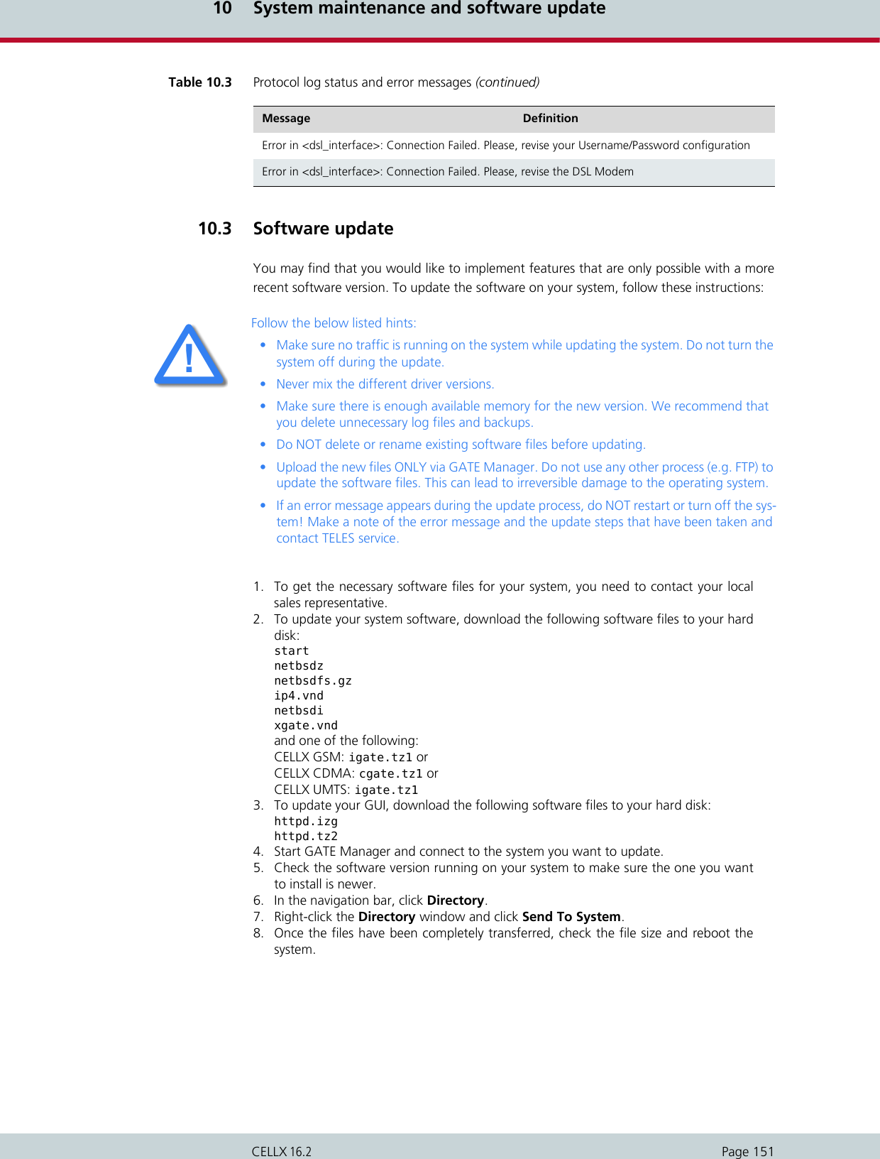
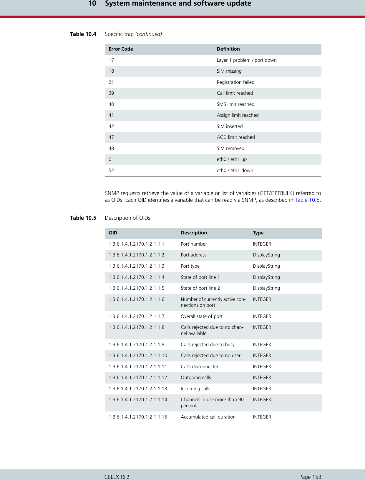
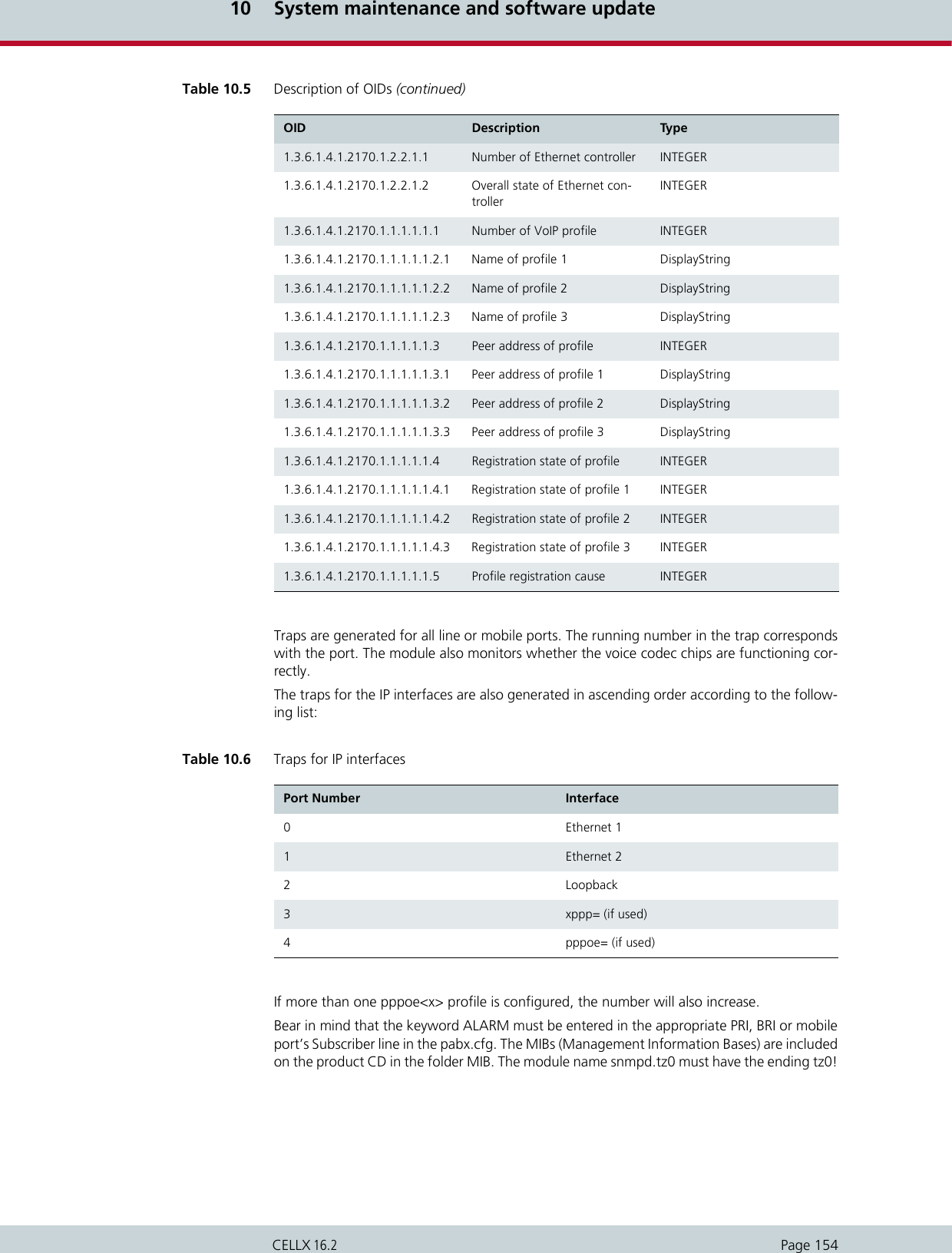
![10 System maintenance and software updatePage 155CELLX 16.2The following settings are possible in the [snmpd] section in the pabx.cfg file: 10.5 DNS forwarderWith this module, the system can function as a DNS server for the clients in the local network.The system in the local network sent the DNS query to the CELLX, which forwards the queriesto a known DNS server address if no valid entry for the query is known. The advantage is that the clients always enter the CELLX’s address as DNS server address, sothat no public DNS server address is required. The CELLX functions in this scenario as a router. Of course, the DNS server’s address can also be transmitted to the clients using the integratedDHCP server. If the CELLX is used as a DSL router or if it sets up a dial-up connection, no entryis required in the pabx.cfg for the parameter NameServer. The DNS server’s address that isnegotiated through this connection will be used.Table 10.7 Settings in the [snmpd]section Parameter DefinitionPort=<port> Defines the target port for the get service (de-fault 161). The port for the trap server is fixed at 162.TrapServer=<ip addr> Enter the SNMP trap server’s IP address. Example for listing more than one: TrapServer=192.168.0.10 192.168.0.12Community=<password> Enter a password for a community (group). The default password is public.The current implementation evaluates the con-figured password only when sending a trap. GET requests use the default value.Example 10.2 Settings in the [snmpd]section[snmpd]TrapServer=192.168.0.1Community=ABCDEThe following software package must be installed: dnsmasg.tz2.ii](https://usermanual.wiki/Teles-Informationstechnologien/CDMA32VOIPUS/User-Guide-1599912-Page-157.png)
![10 System maintenance and software updatePage 156CELLX 16.210.6 ipupdate - DynDNS clientThis function allows you to assign a defined hostname to an IP address that changes dynam-ically. That means that you can always reach a device or service through the public IP network,even if, for example, it is a common DSL connection with dynamic IP address allocation. Sev-eral providers support this service.Make the following entries in the system’s pabx.cfg, in the [DynDNS] section: The following software package must be installed: ipupdate.tz2.iiTable 10.8 pabx.cfg: DynDNS DynDNS Parametersservice=<type>Specifies which provider is used. The following providers are supported:dhsdyndnsdyndns-staticdynsezipeasydnseasydns-partnergnudipheipv6tbhnpgpowodstzozoneedithttp://www.dhs.orghttp://www.dyndns.orghttp://www.dyns.cxhttp://www.ez-ip.nethttp:/www.easydns.comhttp://www.gnudip.cheapnet.nethttp://www.hn.orghttp:www.justlinux.comhttp://ods.orghttp://www.tzo.comhttp://zoneedit.comuser=<username:password>Defines the username and password for the DNS service provider.host=<domain_name_of_dns_service>Enter the domain name that is used.interface=<If>Defines the interface to be used. Possible entries are emac0, emac1, pppoe0. The dynamic IP ad-dress for this interface is transmitted to the service provider.max-interval=<sec>Defines the value in seconds in which actualization of the name in the DNS database must occur. 2073600 seconds (24 days) is the default value. The shortest interval allowed is 60 seconds. Bear in mind that this setting may cause the provider to block the domain name, since multiple regis-trations in short intervals are often not allowed. You must clear this with your provider.](https://usermanual.wiki/Teles-Informationstechnologien/CDMA32VOIPUS/User-Guide-1599912-Page-158.png)
![10 System maintenance and software updatePage 157CELLX 16.2In the following example, the DynDNS service is used and the domain name is host.do-main.de; the username is user and the password is pwd. The CELLX works as DSL router andthe dynamically allocated IP address of the PPPoE interface is used.Included in the possible uses for this feature is remote access to the CELLX when the IP con-nection does not have a fixed IP address. In this case, you can access the system, for examplewith the GATE Manager, if the host name is used in the Remote Number dialog. Example en-try in the Remote Number dialog: IP:host.domain.de.10.7 TraceDuring operation, the trace readouts of the CELLX can be saved in a file or transmitted withremote maintenance directly. The trace options must be turned on in the GATE Manager (of-fline or online trace) or via FTP raw commands (see Chapter 4.10.3 FTP). Trace results present-ed here are for PRI,VoIP, GSM/CDMA/UMTS interfaces and for the following services invarious levels:Example 10.3 DynDNS[DynDNS]service=dyndnsuser=user:pwdhost=host.domain.deinterface=pppoe0max-interval=2073600Table 10.9 Trace optionsOption DefinitionMail Output for all SMTP packets.NumberPortability Output of all packets for communication with the iMNP.VoiceCodecs Output of RTCP information described under VP module.PPP Output of PPP connection information.DTMF Output for DTMF tone detection.Remote Output for GATE Manager and NMS communi-cation. For offline traces only.](https://usermanual.wiki/Teles-Informationstechnologien/CDMA32VOIPUS/User-Guide-1599912-Page-159.png)
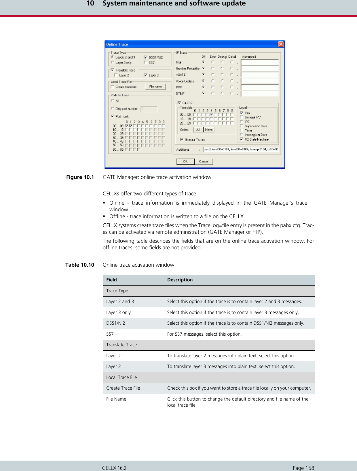
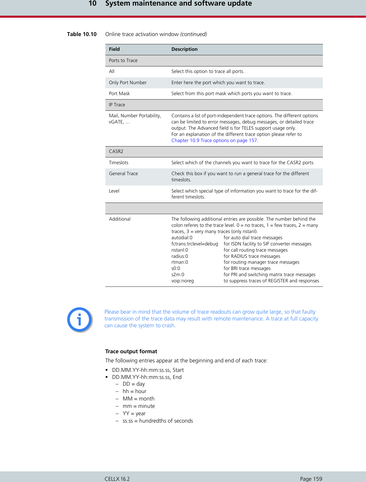
![10 System maintenance and software updatePage 160CELLX 16.2Traces appear in the following format:[<hh:mm:ss>] <module>[<port>]: <trace><module> – s = send for PRI/BRI or mobile ports– r = receive for PRI/BRI or mobile ports– x = send to VoIP destinations– y = receive from VoIP destinations– i = information messages and internal trace outputs between VoIP and the otherinterfaces (ISDN, mobile)– a = VoIP controllers RTCP output–m = mail output– g = remote output<port> – port number (controller number in the pabx.cfg) or 255 if a service is used<trace>– output in the defined syntax for the module10.7.1 ISDN trace outputTrace output for DSS1 are in hexadecimal notation. You can use the external tool Trace-View.exe to translate offline trace output. You will find the tool in the Software folder onthe enclosed CD. The GATE Manager’s trace window can also display translated online traces.The following example shows an untranslated DSS1 trace.Example 10.4 ISDN trace output17.05.06-09:54:40,Start 11.7a (L3)[09:55:14.58] r[00]: 00 01 02 02 08 02 00 02 05 04 03 80 90 a3 18 03 a1 83 81 6c 02 81 31 70 06 81 31 32 33 34 35 7d 02 91 81 [09:55:14.58] s[00]: 02 01 02 04 08 02 80 02 0d 18 03 a9 83 81 [09:55:14.58] s[01]: 00 01 a8 9a 08 02 00 46 05 04 03 80 90 a3 18 03 a1 83 89 6c 02 81 31 70 06 81 31 32 33 34 35 7d 02 91 81 [09:55:14.58] r[01]: 02 01 9a aa 08 02 80 46 0d 18 03 a9 83 89 [09:55:14.86] r[01]: 02 01 9c aa 08 02 80 46 01 [09:55:14.86] s[00]: 02 01 04 04 08 02 80 02 01 [09:55:16.73] r[01]: 02 01 9e aa 08 02 80 46 07 29 05 05 07 01 09 33 4c 07 01 81 31 32 33 34 35 [09:55:16.73] s[01]: 00 01 aa a0 08 02 00 46 0f [09:55:16.73] s[00]: 02 01 06 04 08 02 80 02 07 29 05 05 07 01 09 32 4c 07 01 81 31 32 33 34 35[09:55:16.73] r[00]: 00 01 04 08 08 02 00 02 0f [09:55:44.30] r[00]: 00 01 06 08 08 02 00 02 45 08 02 80 90 [09:55:44.35] s[01]: 00 01 ac a0 08 02 00 46 45 08 02 80 90 [09:55:46.71] r[01]: 02 01 a0 ae 08 02 80 46 4d [09:55:46.71] s[01]: 00 01 ae a2 08 02 00 46 5a [09:55:46.71] s[00]: 02 01 08 08 08 02 80 02 4d [09:55:46.71] r[00]: 00 01 08 0a 08 02 00 02 5a 17.05.06-09:51:33,End](https://usermanual.wiki/Teles-Informationstechnologien/CDMA32VOIPUS/User-Guide-1599912-Page-162.png)
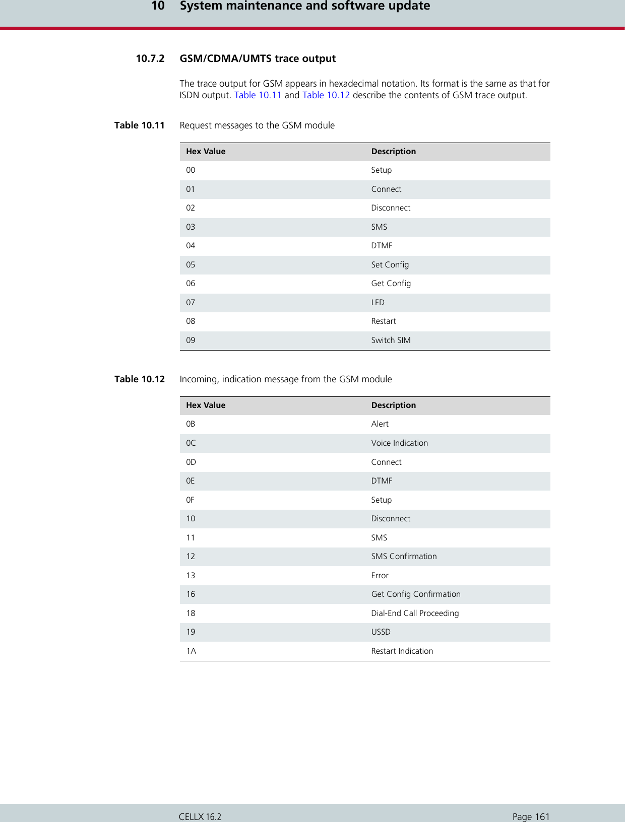
![10 System maintenance and software updatePage 162CELLX 16.2The following example shows a GSM call through the fourth GSM controller.10.7.3 VoIP trace outputAs described above in Chapter 10.7 Trace, there are four modules for VoIP traces. The groupsx (send), y (receive) and i (information and internal output) appear when a Layer2 or Layer3offline or online trace is started. Group a (RTCP output) only appears when the module VoiceCodecs is active.Particularly in the case of VoIP connections (protocols H.323 and SIP), the trace output is quiteextensive and abbreviations make it difficult to keep track of the results. The following listcontains a description of H.323 output. Output for the signaling protocol SIP is transmitted in ASCII and translated for better legibility.Since they are displayed unabridged, no description is necessary. Information and internaloutput traces correspond with the H.323 output and are described in the following tables.For ENUM, please refer to Chapter 10.7.3.5 ENUM output.In general, the following rules apply for this trace output: The information is thoroughly analyzed where it is received (all rcv messages). Example 10.5 GSM call through fourth GSM controllerStatus Request[14:57:51.80] s[04]: 06Status Information: [14:57:51.80] r[04]: 16 Setup Request:[14:57:52.29] s[04]: 00 4c 93 04 00 00 00 35 36 36 37 00 35 38 2c 36 34 36 2c 33 30 2c 2c 2c 30 2c 2c 2c 30 2c 32 36 32 2c 30 37 2c 00 72 64 09 75 70 20 7b 64 35 7d 20 27 2e 2e 2b 43 43 45 44 3a 20 32 36 32 2c 30 37 2c 34 Dial End:[14:57:55.47] r[04]: 18 Alert:[14:57:55.63] r[04]: 0b Connect Indication:[14:57:56.63] r[04]: 0d Disconnect Request:[14:59:54.13] s[04]: 02 4c 93 00 Disconnect Indication:[14:59:54.19] r[04]: 10Table 10.13 H.323 output Packet Descriptionh225 H.225-protocol messages.h245 H.245-protocol messages.pstn Messages of the internal protocol interface that provides the interface to the other interfaces PRI, BRI and GSM.rcv Coming from the IP network or the internal pro-tocol interface; appears with <dir> in the trace lines.snd Sending to the IP network or the internal proto-col interface; appears with <dir> in the trace lines.](https://usermanual.wiki/Teles-Informationstechnologien/CDMA32VOIPUS/User-Guide-1599912-Page-164.png)
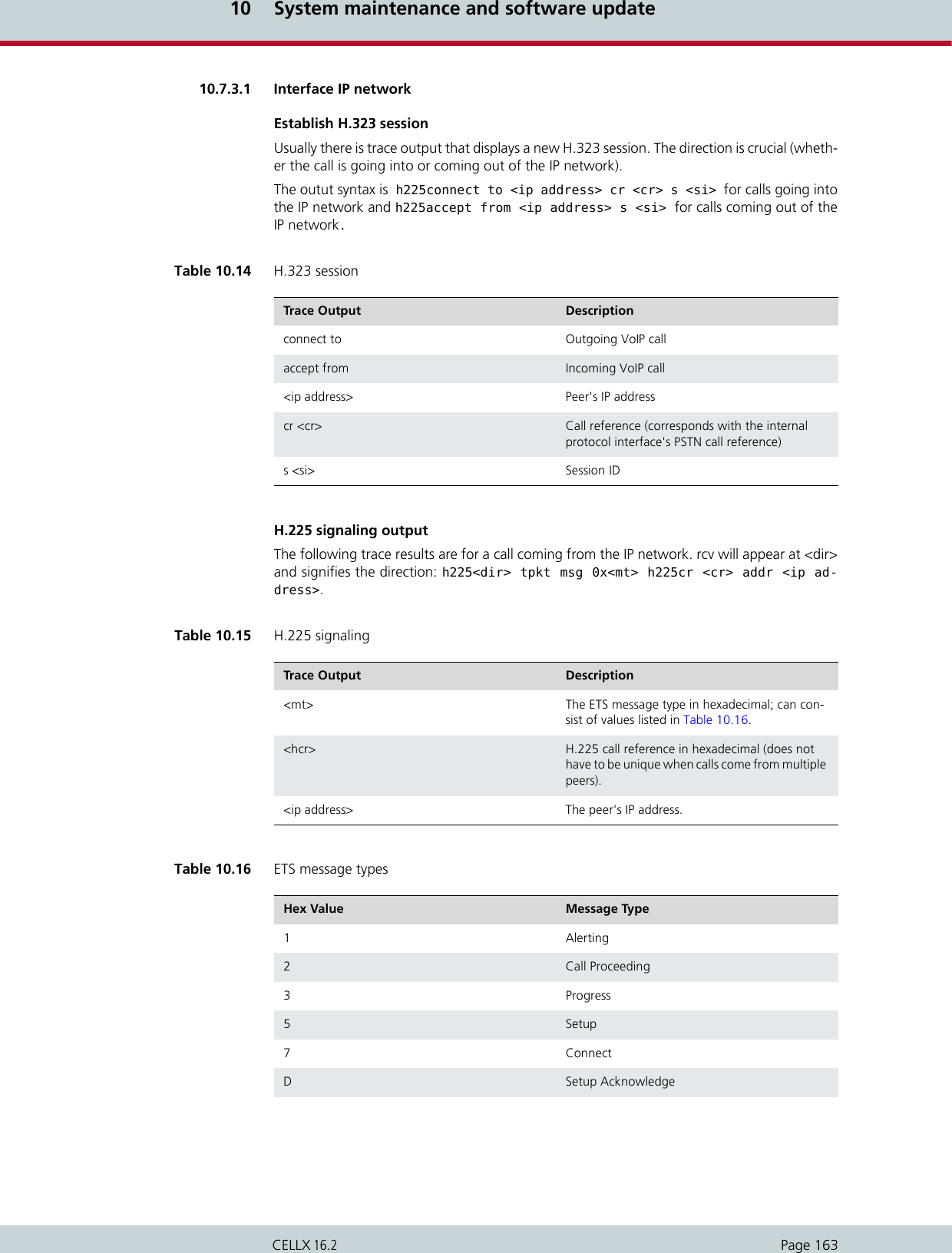
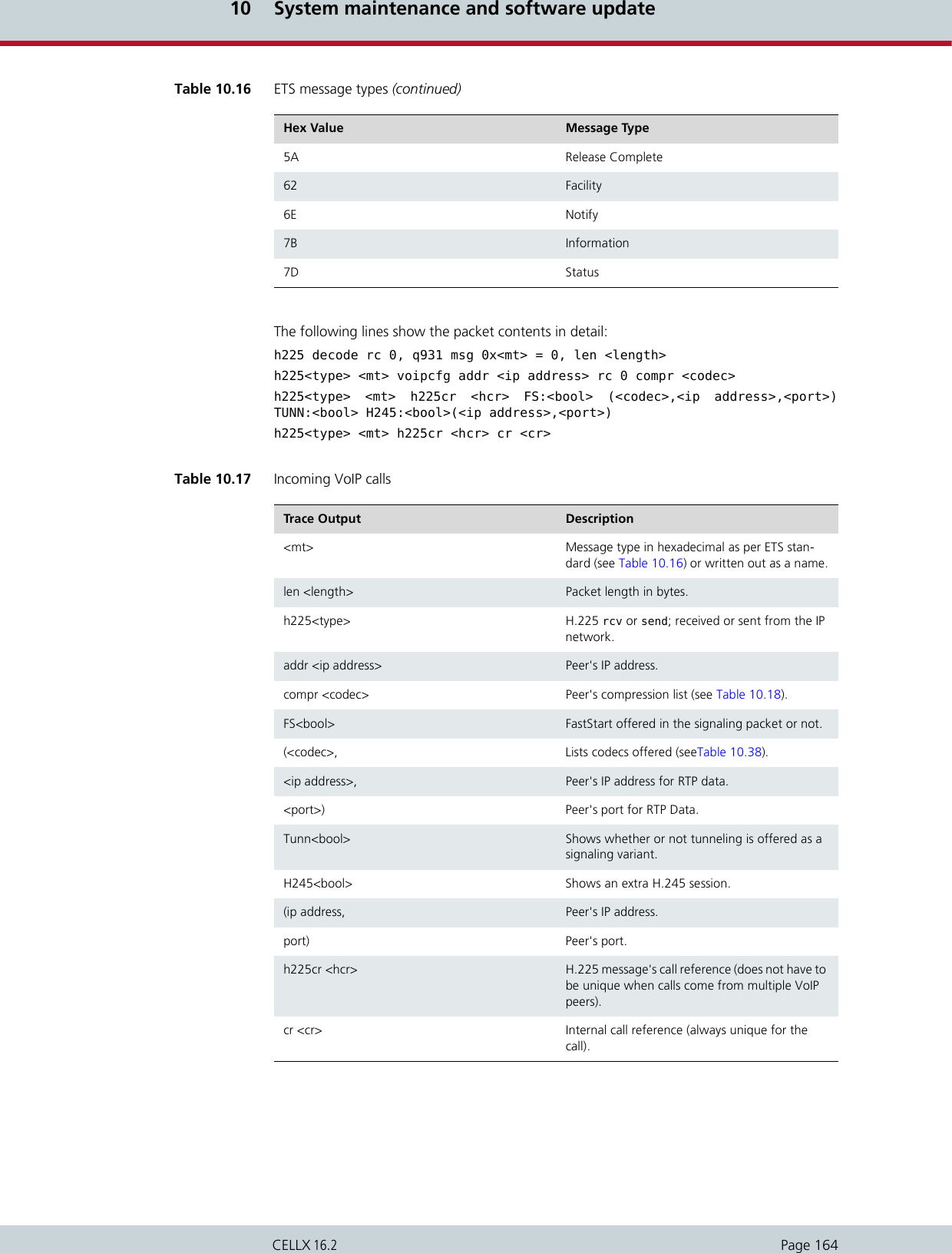
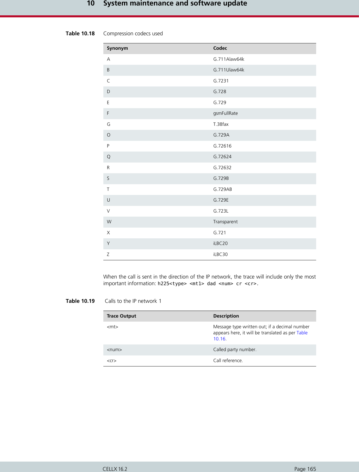
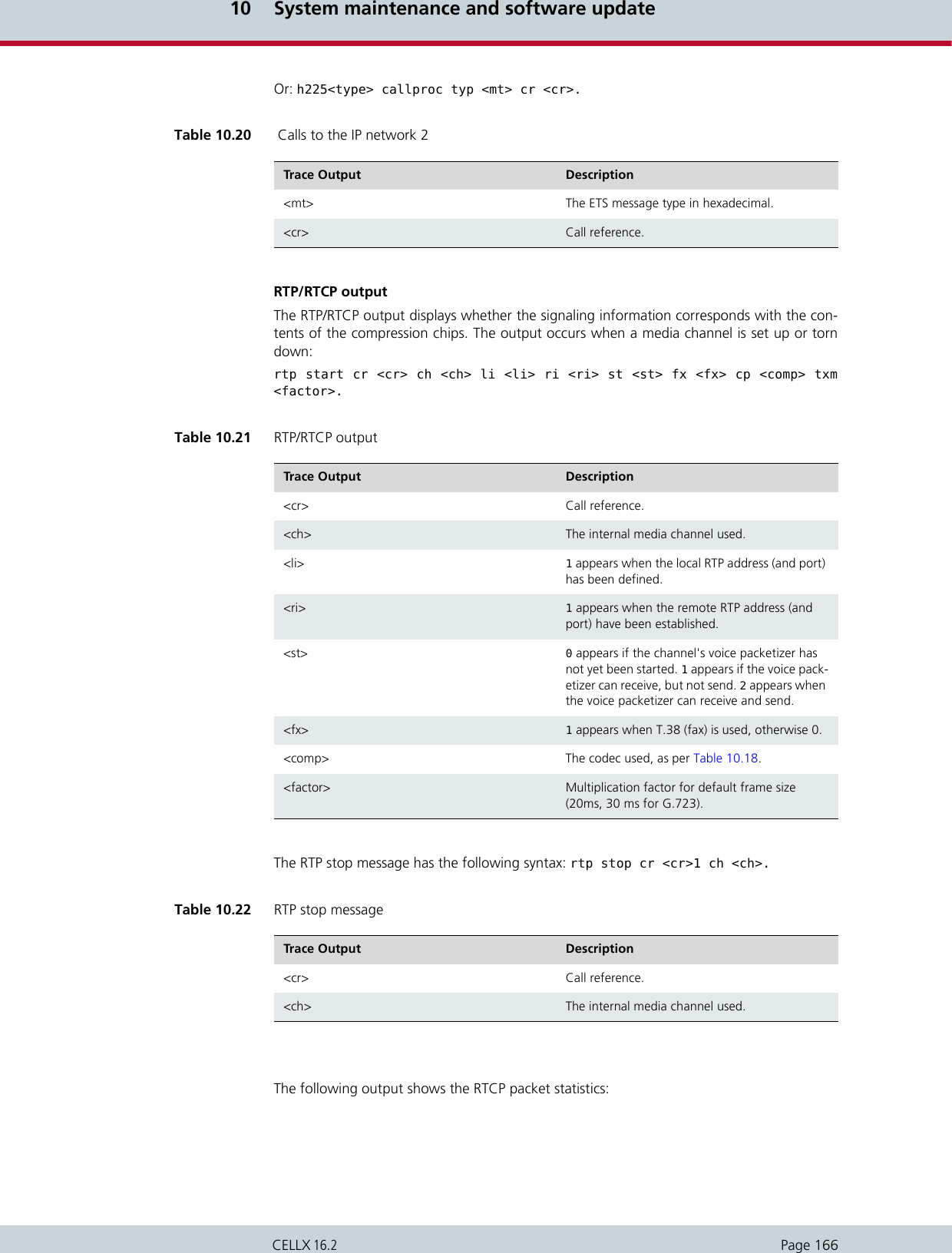
![10 System maintenance and software updatePage 167CELLX 16.2rtcp <ch>: SR <dir> pc <pc> oc <oc> ji <ji> rt <rt> fl <fl> cl <cl>.The following output shows the jitter buffer status:a[<controller>]: <VoIPcodecChipType> ch <ch> jitter buffer n1 n2 n3n4 n5n6 n7 n8.An RTP connection has ended when the following trace output appears:Table 10.23 RTCP packet statistics Trace Output Description<ch> The internal media channel used.SR<dir> Rx sender report (received) is more interesting, since it comes from the peer. Tx sender report (transmitted).<pc> Packet count (number of packets transmitted/re-ceived).<oc> Octet count (number of octets transmitted/re-ceived).<ji> Delay jitter [msec].<rt> Round-trip local<->remote, round-trip delay [msec].<fl> Fraction lost: Fraction of packets lost [8lsb].<cl> Cumulative lost: number of lost packets [24lsb].Table 10.24 Jitter buffer status Trace Output Descriptionn1 SteadyStateDelay in millisecondsn2 NumberOfVoiceUnderrunn3 NumberOfVoiceOverrunn4 NumberOfVoiceDecoderBfi (bfi = bad frame in-terpolation)n5 NumberOfVoicePacketsDroppedn6 NumberOfVoiceNetPacketsLostn7 NumberOfIbsOverrun (ibs = in band signaling)n8 NumberOfCasOverrun](https://usermanual.wiki/Teles-Informationstechnologien/CDMA32VOIPUS/User-Guide-1599912-Page-169.png)
![10 System maintenance and software updatePage 168CELLX 16.2a[<controller>]: <VoIPcodecChipType> stop ch=<ch>.The following output results when the codec changes for a fax connection: a[<controller>]: ac49x ch <ch> fax/data n1 n2 n3.Table 10.25 RTP stop message (VP module) Trace Output Description<ch> The internal media channel used.Table 10.26 Codec change for fax Trace Output Descriptionn1 Fax bypass flag:0Voice, data bypass or fax relay1Fax bypassn2 Signal detected on decoder output (see Table 10.27)n3 Signal detected on encoder input (see Table 10.27)Table 10.27 fax or data signal event Value Definition Description0SILENCE_OR_UNKNOWN Undefined (unknown signal or silence)1FAX_CNG CNG-FAX (calling fax tone, 1100 Hz)2ANS_TONE_2100_FAX_CED_OR_MODEMFAX-CED or modem-ANS (an-swer tone, 2100 Hz)3ANS_TONE_WITH_REVERSALS ANS (answer tone with rever-sals)4ANS_TONE_AM ANSam (AM answer tone)5ANS_TONE_AM_REVERSALS ANSam (AM answer tone with reversals)6FAX_V21_PREAMBLE_FLAGS FAX-V.21 preamble flags7FAX_V8_JM_V34 FAX-V.8 JM (fax call function, V.34 fax)8VXX_V8_JM_VXX_DATA V.XX-V.8 JM (data call func-tion, V-series modem)9V32_AA V.32 AA (calling modem tone, 1800 Hz)10 V22_USB1 V.22 USB1 (V.22(bis) unscram-bled binary ones)](https://usermanual.wiki/Teles-Informationstechnologien/CDMA32VOIPUS/User-Guide-1599912-Page-170.png)
![10 System maintenance and software updatePage 169CELLX 16.2Fax relay is activated for the corresponding channel:a[<controller>]: Ac49xActivateFaxRelayCommand(1) ch <ch> rc <cr>.The following output shows various values for fax transmission (see Table 10.28 for a descrip-tion of the values):a[<controller>]: ac49x ch <ch> faxrelay: n1 n2 n3 n4 n5 n6 n7 n8 n9 n10 n11n12 n13 n14 n15 n16 n17.11 V8_BIS_INITIATING_DUAL_TONEV.8bis initiating dual tone (1375 Hz and 2002 Hz)12 V8_BIS_RESPONDING_DUAL_TONEV.8bis responding dual tone (1529 Hz and 2225 Hz)13 VXX_DATA_SESSION V.XX data session14 V21_CHANNEL_2 V.21 channel 2 (mark tone, 1650 Hz)15 V23_FORWARD_CHANNEL V.23 forward channel (mark tone, 1300 Hz)16 V21_CHANNEL_1=18 V.21 channel 1 (mark tone, 980 Hz)17 BELL_103_ANSWER_TONE Bell 103 answer tone, 2225 Hz18 TTY TTY19 FAX_DCN FAX-DCN (G.3 fax disconnect signal)Table 10.27 fax or data signal event (continued)Value Definition DescriptionTable 10.28 Fax status Value Field Name Descriptionn1 UnableToRecoverFlag (0 no, 1 yes) Unable to recover lost packetn2 IllegalHdlcFrameDetectedFlag (...) Illegal HDLC frame detectedn3 FaxExitWithNoMcfFrameFlag Fax exit with no MCF Framen4 HostTransmitOverRunFlag Channel received a buffer overrunn5 HostTransmitUnderRunFlag Channel received a buffer underrunn6 InternalErrorFlag Internal errorn7 ReceivedBadCommandFlag A bad command was received. Words 8 and 9 describe the bad command n8 TimeOutErrorFlag A timeout error occurred](https://usermanual.wiki/Teles-Informationstechnologien/CDMA32VOIPUS/User-Guide-1599912-Page-171.png)
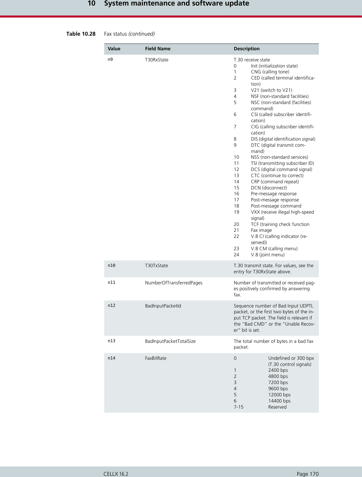
![10 System maintenance and software updatePage 171CELLX 16.2The following output appears when the compression chip detects DTMF tones:a[<controller]: ac49x ch <ch> ibs <dtmf> <dir> <mode> <lev> <dur>.10.7.3.2 Internal protocol interface (to ISDN, mobile)These trace outputs always begin with the keyword pstn, followed by the direction and themessage type. The message is then either concluded or other information follows: n15 DemodulationStatus 0 EQM and Timing Off-set fields are invalid. 1 EQM and Timing Off-set fields are valid.n16 EyeQualityMonitor (EQM) Eye Quality Monitor measure for TCF or fax image. The value of 0 corresponds to the best quality of demodulation. Values greater than 100 have a nega-tive influence on the quality of the fax image.n17 TimingOffsetPpm Timing Offset (ppm) recovered during demodulation of TCF or fax image. The offset is a short integer equal to the sum of the sampling rate error and the sending fax baud rate offset. The value is in integers and and may not exceed 50 ppm in the following ranges during fax transmission (T30TxState): 65535 – 65486 (-50ppm) 0 – 50 (+50ppm)Table 10.28 Fax status (continued)Value Field Name DescriptionTable 10.29 DTMF tone detectionTrace Output Description<ch> Media channel<dtmf> Detected DTMF tone in the stream or as per RFC2833<dir> Direction0Coming from BRI/analog1Coming from VoIP<mode> 0Tone has ended1Tone has been detected<lev> Signal level in -dBm<dur> Tone duration](https://usermanual.wiki/Teles-Informationstechnologien/CDMA32VOIPUS/User-Guide-1599912-Page-173.png)
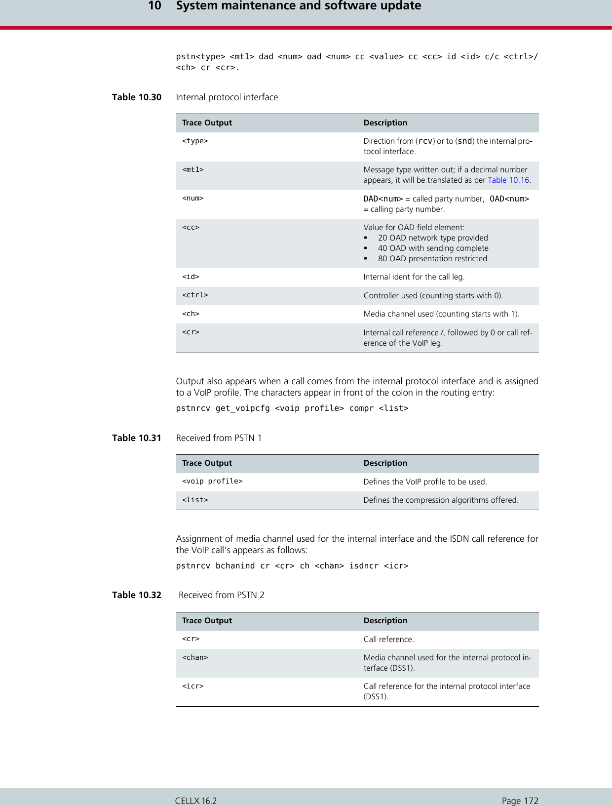
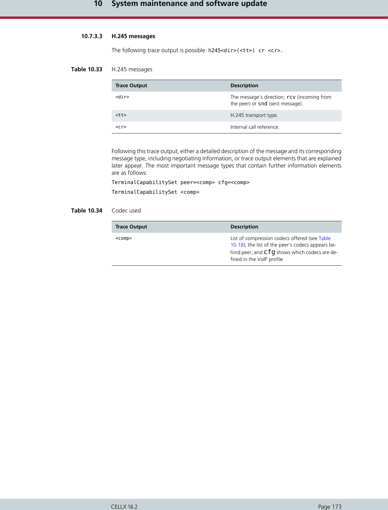
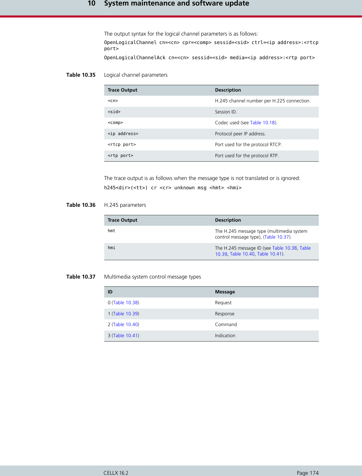
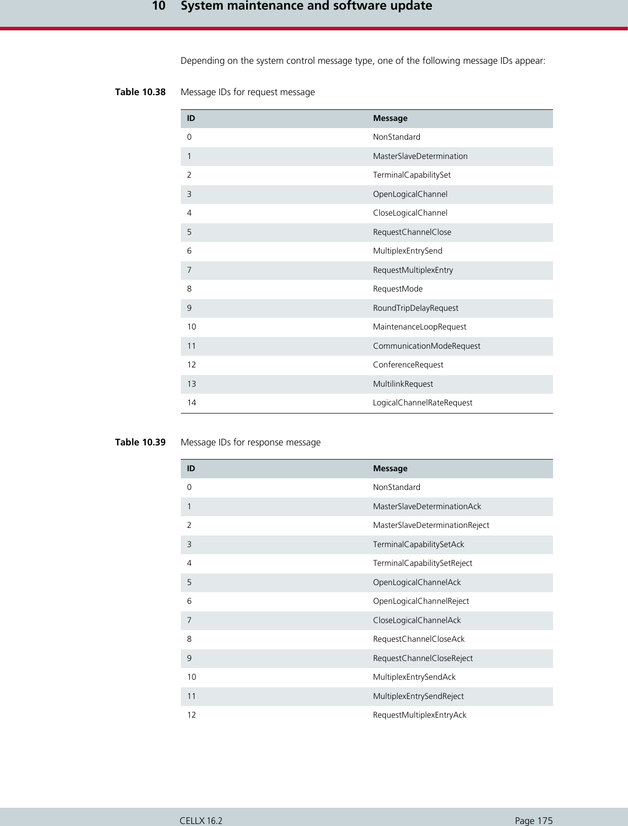
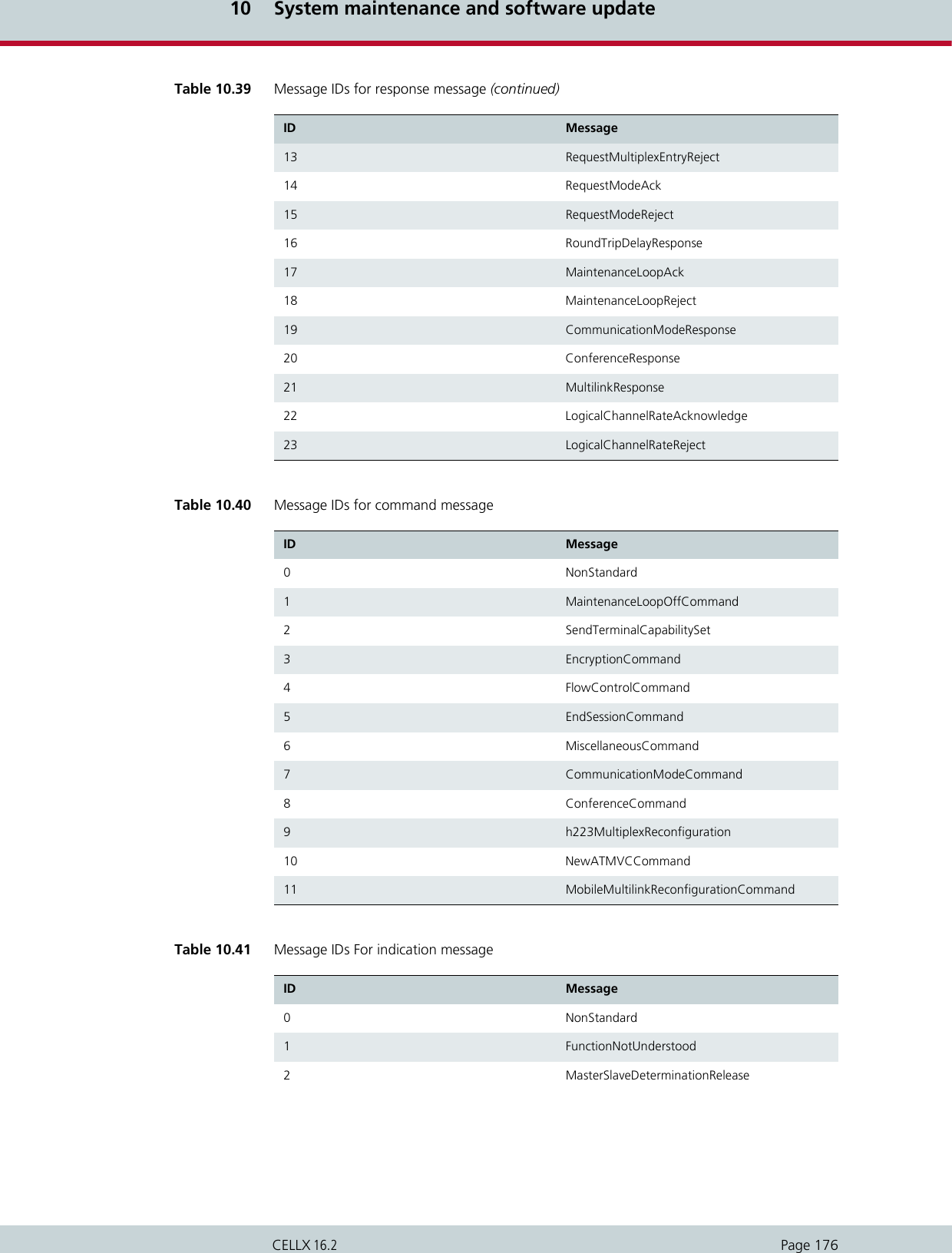
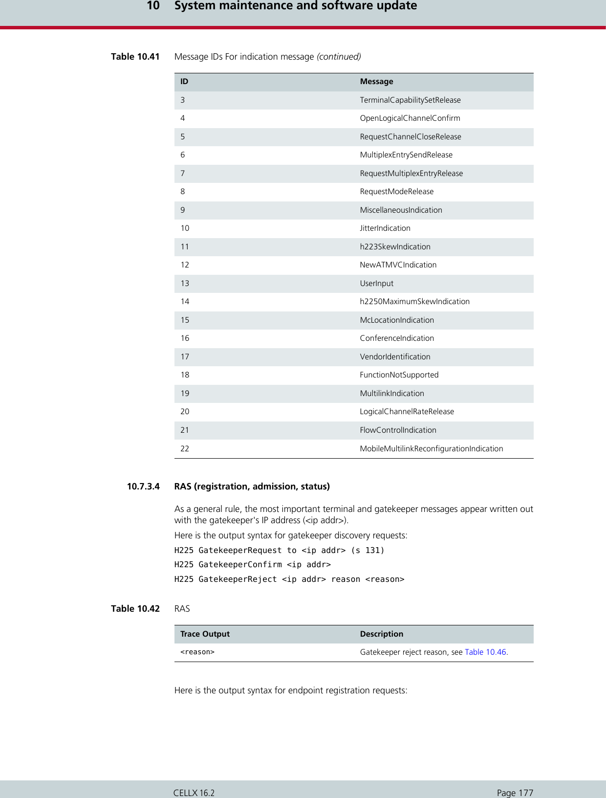
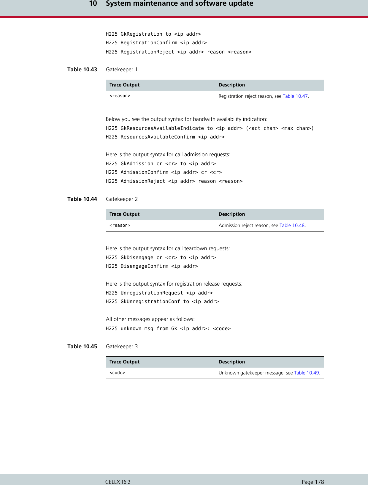
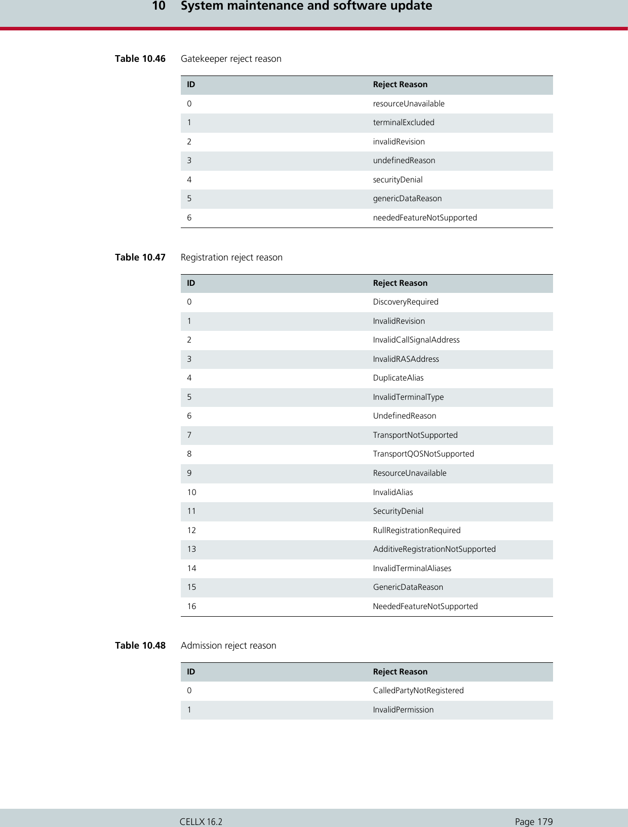
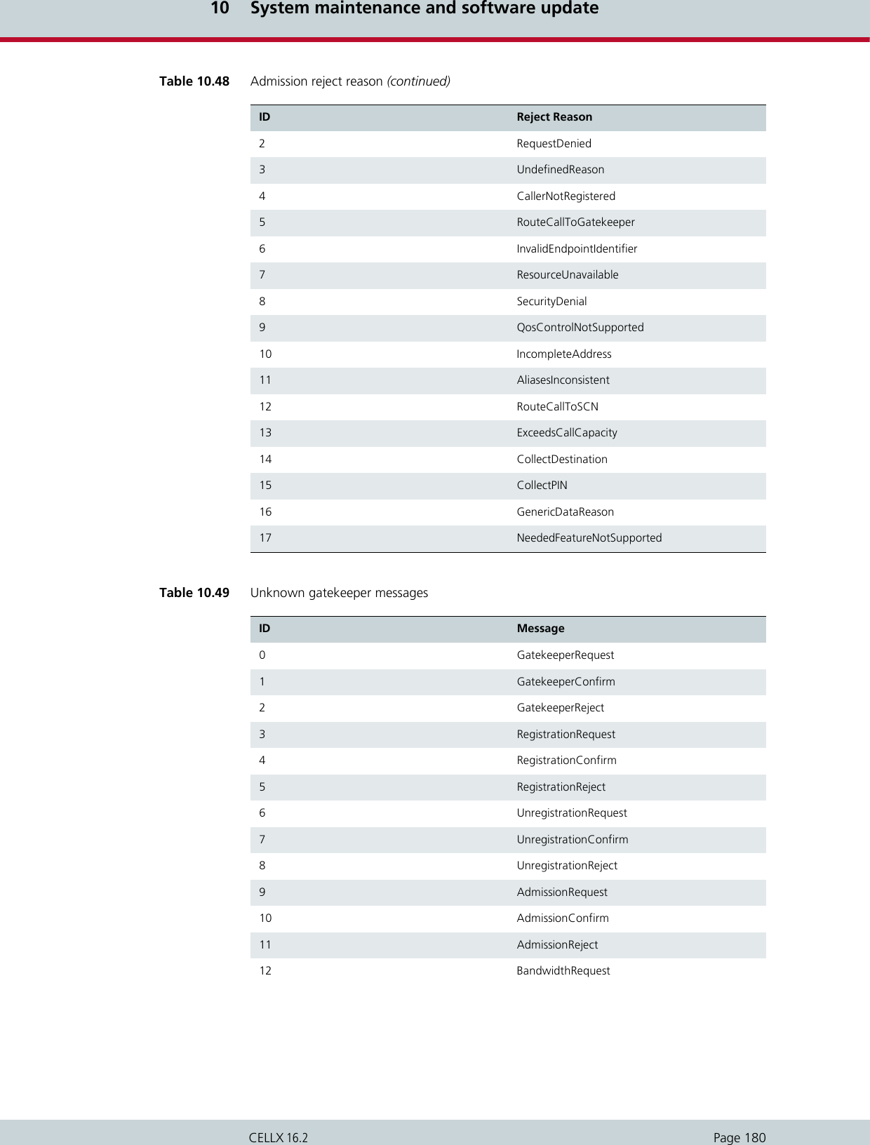
![10 System maintenance and software updatePage 181CELLX 16.210.7.3.5 ENUM outputThis output is assigned to group i and occurs with Layer2 and Layer3 traces:i[<controller>]: enum_query cr <CR> ch <CH>: <num> -> <length> <<answerpattern>>.13 BandwidthConfirm 14 BandwidthReject 15 DisengageRequest 16 DisengageConfirm 17 DisengageReject 18 LocationRequest 19 LocationConfirm 20 LocationReject 21 InfoRequest 22 InfoRequestResponse 23 NonStandardMessage 24 UnknownMessageResponse 25 RequestInProgress 26 ResourcesAvailableIndicate 27 ResourcesAvailableConfirm 28 InfoRequestAck 29 InfoRequestNak 30 ServiceControlIndication 31 ServiceControlResponse Table 10.49 Unknown gatekeeper messages (continued)ID MessageTable 10.50 ENUM output Trace Output Description<cr> Call reference.<ch> Media channel.<num> Phone number converted into ENUM domain format.<length> Length of the answer field in the DNS response in bytes. 0 appears if the number was not found.<answer pattern> Displays the DNS response. 0 appears if the num-ber was not found.](https://usermanual.wiki/Teles-Informationstechnologien/CDMA32VOIPUS/User-Guide-1599912-Page-183.png)
![10 System maintenance and software updatePage 182CELLX 16.210.7.3.6 ExamplesThe following examples are offline traces. You can generate them using the GATE Manageror FTP commands. The filename is trace.log. The following cases appear in the examples:Incoming H.323 call with FastStart (please see "Incoming H.323 call with FastStart" onpage 182 )Outgoing H.323 call with FastStart (please see "Outgoing H.323 call with FastStart" onpage 183)Fax call (please see "Fax call" on page 184)Incoming H.323 call with FastStartExample 10.6 Incoming H.323 call with FastStart[15:25:13.65] i[02]: h225accept from 172.16.0.200 s 4[15:25:13.75] y[02]: h225rcv tpkt msg 5 h225cr 8006 addr 172.16.0.200 pt 0[15:25:13.75] y[02]: h225 decode rc 0, q931 msg 5 (0), len 364[15:25:13.75] y[02]: h225rcv setup voipcfg addr 172.16.0.200 rc 0 <DF> compr EABG[15:25:13.75] y[02]: h225rcv faststart <A1B1E1G0>[15:25:13.75] y[02]: h225rcv setup oad 01 00 <111> <> dad 01 <123456> rad <> bc 038090a3 0101[15:25:13.75] y[02]: h225rcv setup h225cr 8006 FS:1(E,172.16.0.200,29000) TUNN:1 H245:0(0,0)[15:25:13.75] y[02]: h225rcv setup h225cr 8006 cr 7[15:25:13.75] i[02]: pstnsnd setup dad 123456 oad 1 cr 7 s 4[15:25:13.75] s[00]: 00 01 52 4c 08 02 00 08 05 04 03 80 90 a3 18 03 a1 83 87 6c 04 81 31 31 31 70 07 81 31 32 33 34 35 36 7d 02 91 81 [15:25:13.75] i[02]: pstnrcv connresp cr 7 acc 5 ch 1[15:25:13.75] x[02]: h225snd callproc typ d cr 7 pri 0[15:25:13.75] r[00]: 00 01 01 54 [15:25:13.75] r[00]: 02 01 4c 54 08 02 80 08 0d 18 03 a9 83 87 [15:25:13.75] s[00]: 02 01 01 4e [15:25:14.33] r[00]: 02 01 4e 54 08 02 80 08 01 [15:25:14.33] s[00]: 02 01 01 50 [15:25:14.33] i[02]: pstnrcv alert cr 7 cls ff[15:25:14.33] i[02]: rtp start cr 7 ch 1 li 1 ri 1 st 2 fx 0 cp E txm 1[15:25:14.33] x[02]: h225snd callproc typ 1 cr 7 pri 8[15:25:14.34] a[02]: vp start(201) ch=0 local=29000 remote=ac1000c8:29000 agg=0 pcm=0[15:25:14.38] a[02]: vp rtcp 0: RR Tx pc 0 oc 0 ji -1 rt 0 fl -1 cl -1[15:25:14.38] a[02]: vp ch 0: in 0 out 74[15:25:15.57] r[00]: 02 01 50 54 08 02 80 08 07 29 05 06 03 18 0f 17 4c 06 01 81 31 37 33 31 [15:25:15.57] s[00]: 00 01 54 52 08 02 00 08 0f [15:25:15.57] i[02]: pstnrcv connresp cr 7 acc 10 ch 255[15:25:15.57] x[02]: h225snd callproc typ 7 cr 7 pri 0[15:25:15.58] r[00]: 00 01 01 56 [15:25:17.01] a[02]: vp rtcp 0: SR Rx pc 110 oc 1816 ji 158 rt -1 fl 2 cl 1[15:25:20.09] a[02]: vp rtcp 0: SR Tx pc 277 oc 5496 ji 164 rt 0 fl 0 cl 0[15:25:20.09] a[02]: vp ch 0: in 18166 out 20646[15:25:20.09] a[02]: vp rtcp 0: SR Rx pc 258 oc 4634 ji 208 rt -1 fl 0 cl 1[15:25:23.32] a[02]: vp rtcp 0: SR Tx pc 441 oc 8776 ji 176 rt 0 fl 0 cl 0[15:25:23.32] a[02]: vp ch 0: in 28966 out 32900[15:25:24.68] y[02]: h225rcv tpkt msg 5a h225cr 8006 addr 172.16.0.200 pt 800e7800[15:25:24.68] y[02]: h225 decode rc 0, q931 msg 5a (5), len 33[15:25:24.68] y[02]: h225rcv relack h225cr 8006 FS:0(-,0,0) TUNN:1 H245:0(0,0)[15:25:24.68] y[02]: h225rcv relack h225cr 8006 cau 0x10[15:25:24.68] i[02]: rtp hold cr 7 ch 1[15:25:24.68] s[00]: 00 01 56 52 08 02 00 08 45 08 02 80 90 [15:25:24.68] i[02]: h225 connection 4 terminated[15:25:24.69] r[00]: 00 01 01 58 [15:25:25.89] r[00]: 02 01 52 58 08 02 80 08 4d [15:25:25.89] s[00]: 00 01 58 54 08 02 00 08 5a [15:25:25.94] i[02]: pstnrcv terminate connection (3201) cr 7 cau 1 err 16 state 17 ch 1 rsid 1[15:25:25.94] i[02]: rtp stop cr 7 ch 1[15:25:25.94] r[00]: 00 01 01 5a [15:25:25.94] a[02]: vp ch 0: in 34096 out 38154[15:25:25.94] a[02]: vp stop ch=0](https://usermanual.wiki/Teles-Informationstechnologien/CDMA32VOIPUS/User-Guide-1599912-Page-184.png)
![10 System maintenance and software updatePage 183CELLX 16.2Outgoing H.323 call with FastStartExample 10.7 Outgoing H.323 call with FastStart[15:04:09.12] r[00]: 02 01 46 48 08 02 22 54 05 04 03 80 90 a3 18 03 a9 83 94 6c 06 01 81 31 31 31 31 70 04 81 33 32 31 7d 02 91 81 [15:04:09.12] s[00]: 02 01 01 48 [15:04:09.12] s[00]: 00 01 48 48 08 02 a2 54 0d 18 03 a9 83 94 [15:04:09.12] i[02]: pstnrcv setup dad DF:321 oad 1111 cc 0 id 15d006[15:04:09.12] i[02]: pstnrcv get_voipcfg <DF>[15:04:09.12] i[02]: h225connect to 172.16.0.200 cr 6[15:04:09.12] x[02]: h225snd setup dad 1 cr 6[15:04:09.12] r[00]: 00 01 01 4a [15:04:09.15] y[02]: h225rcv tpkt msg d h225cr 6 addr 172.16.0.200 pt 80412800[15:04:09.15] y[02]: h225 decode rc 0, q931 msg d (11), len 32[15:04:09.15] y[02]: h225rcv msg d (11) h225cr 6 FS:0(-,0,0) TUNN:1 H245:0(0,0)[15:04:09.50] y[02]: h225rcv tpkt msg 1 h225cr 6 addr 172.16.0.200 pt 80412800[15:04:09.50] y[02]: h225 decode rc 0, q931 msg 1 (3), len 121[15:04:09.50] y[02]: h225rcv faststart <E1>[15:04:09.50] y[02]: h225rcv alert h225cr 6 FS:1(E,172.16.0.200,29000) TUNN:1 H245:0(0,0)[15:04:09.50] i[02]: rtp start cr 6 ch 1 li 1 ri 1 st 2 fx 0 cp E txm 1[15:04:09.50] s[00]: 00 01 4a 48 08 02 a2 54 01 1e 02 80 88 [15:04:09.50] a[02]: vp start(201) ch=0 local=29000 remote=ac1000c8:29000 agg=0 pcm=0[15:04:09.50] r[00]: 00 01 01 4c [15:04:09.53] a[02]: vp rtcp 0: RR Tx pc 0 oc 0 ji -1 rt 0 fl -1 cl -1[15:04:09.53] a[02]: vp ch 0: in 0 out 74[15:04:11.79] y[02]: h225rcv tpkt msg 7 h225cr 6 addr 172.16.0.200 pt 80412800[15:04:11.79] y[02]: h225 decode rc 0, q931 msg 7 (2), len 79[15:04:11.79] y[02]: h225rcv connect h225cr 6 FS:0(-,0,0) TUNN:1 H245:0(0,0)[15:04:11.79] i[02]: pstnsnd connect cr 6[15:04:11.79] s[00]: 00 01 4c 48 08 02 a2 54 07 [15:04:11.80] r[00]: 02 01 48 4e 08 02 22 54 0f [15:04:11.80] s[00]: 02 01 01 4a [15:04:12.50] a[02]: vp rtcp 0: SR Rx pc 21 oc 394 ji 201 rt -1 fl 0 cl 0[15:04:16.13] a[02]: vp rtcp 0: SR Tx pc 192 oc 3236 ji 196 rt 0 fl 0 cl 0[15:04:16.13] a[02]: vp ch 0: in 14612 out 13796[15:04:17.98] y[02]: h225rcv tpkt msg 5a h225cr 6 addr 172.16.0.200 pt 80412800[15:04:17.98] y[02]: h225 decode rc 0, q931 msg 5a (5), len 33[15:04:17.98] y[02]: h225rcv relack h225cr 6 FS:0(-,0,0) TUNN:1 H245:0(0,0)[15:04:17.98] y[02]: h225rcv relack h225cr 6 cau 0x10[15:04:17.98] i[02]: rtp hold cr 6 ch 1[15:04:17.98] s[00]: 00 01 4e 4a 08 02 a2 54 45 08 02 80 90 [15:04:17.98] i[02]: h225 connection 4 terminated[15:04:17.99] r[00]: 00 01 01 50 [15:04:18.04] r[00]: 02 01 4a 50 08 02 22 54 4d 08 02 84 90 [15:04:18.04] s[00]: 00 01 50 4c 08 02 a2 54 5a [15:04:18.06] i[02]: pstnrcv terminate connection (3201) cr 6 cau 90 err 16 state 17 ch 1 rsid 1[15:04:18.06] i[02]: rtp stop cr 6 ch 1[15:04:18.06] r[00]: 00 01 01 52 [15:04:18.06] a[02]: vp ch 0: in 21288 out 20708[15:04:18.06] a[02]: vp stop ch=0](https://usermanual.wiki/Teles-Informationstechnologien/CDMA32VOIPUS/User-Guide-1599912-Page-185.png)
![10 System maintenance and software updatePage 184CELLX 16.2Fax callExample 10.8 Fax call [16:00:40.44] i[02]: h225accept from 172.20.0.200 s 4[16:00:40.49] y[02]: h225rcv tpkt msg 5 h225cr 8007 addr 172.20.0.200 pt 0[16:00:40.49] y[02]: h225 decode rc 0, q931 msg 5 (0), len 251[16:00:40.49] y[02]: h225rcv setup voipcfg addr 172.20.0.200 rc 0 <DF> compr EABG[16:00:40.49] y[02]: h225rcv faststart <E0G0>[16:00:40.49] y[02]: h225rcv setup oad 00 00 <> <> dad 01 <123456> rad <> bc 038090a3 0101[16:00:40.49] y[02]: h225rcv setup h225cr 8007 FS:1(E,172.20.0.200,29000) TUNN:1 H245:0(0,0)[16:00:40.49] y[02]: h225rcv setup h225cr 8007 cr 14[16:00:40.49] i[02]: pstnsnd setup dad 123456 oad cr 14 s 4[16:00:40.49] s[00]: 00 01 5a 54 08 02 00 09 05 04 03 80 90 a3 18 03 a1 83 88 70 07 81 31 32 33 34 35 36 7d 02 91 81 [16:00:40.49] i[02]: pstnrcv connresp cr 14 acc 5 ch 1[16:00:40.49] x[02]: h225snd callproc typ d cr 14 pri 0[16:00:40.50] r[00]: 02 01 54 5c 08 02 80 09 0d 18 03 a9 83 88 [16:00:40.67] r[00]: 02 01 56 5c 08 02 80 09 01 [16:00:40.67] i[02]: pstnrcv alert cr 14 cls ff[16:00:40.67] i[02]: rtp start cr 14 ch 1 li 1 ri 1 st 2 fx 0 cp E txm 2[16:00:40.67] x[02]: h225snd callproc typ 1 cr 14 pri 8[16:00:40.70] a[02]: vp start(201) ch=0 local=29000 remote=ac1000c8:29000 agg=0 pcm=0[16:00:40.74] a[02]: vp rtcp 0: RR Tx pc 0 oc 0 ji -1 rt 0 fl -1 cl -1[16:00:40.74] a[02]: vp ch 0: in 0 out 74[16:00:40.90] r[00]: 02 01 58 5c 08 02 80 09 07 29 05 06 03 18 0f 3b 4c 08 01 81 31 32 33 34 35 36[16:00:40.90] s[00]: 00 01 5c 5a 08 02 00 09 0f [16:00:40.90] i[02]: pstnrcv connresp cr 14 acc 10 ch 255[16:00:40.90] x[02]: h225snd callproc typ 7 cr 14 pri 0[16:00:41.98] a[02]: vp rtcp 0: SR Rx pc 134 oc 1340 ji 195 rt -1 fl 0 cl 0[16:00:43.29] y[02]: h225rcv tpkt msg 62 h225cr 8007 addr 172.20.0.200 pt 80410800[16:00:43.29] y[02]: h225 decode rc 0, q931 msg 62 (6), len 123[16:00:43.29] y[02]: h225rcv facility h225cr 8007 FS:0(-,0,0) TUNN:1 H245:0(0,0)[16:00:43.29] i[02]: h245rcv(1) cr 14 TerminalCapabilitySet peer=<EG> cfg=<EABG>[16:00:43.29] i[02]: h245snd(1) cr 14 TerminalCapabilitySetAck[16:00:43.29] i[02]: h245snd(1) cr 14 TerminalCapabilitySet <EABG>[16:00:43.51] y[02]: h225rcv tpkt msg 62 h225cr 8007 addr 172.20.0.200 pt 80410800[16:00:43.51] y[02]: h225 decode rc 0, q931 msg 62 (6), len 63[16:00:43.51] y[02]: h225rcv facility h225cr 8007 FS:0(-,0,0) TUNN:1 H245:0(0,0)[16:00:43.51] i[02]: h245rcv(1) cr 14 TerminalCapabilitySetAck[16:00:43.72] y[02]: h225rcv tpkt msg 62 h225cr 8007 addr 172.20.0.200 pt 80410800[16:00:43.72] y[02]: h225 decode rc 0, q931 msg 62 (6), len 74[16:00:43.72] y[02]: h225rcv facility h225cr 8007 FS:0(-,0,0) TUNN:1 H245:0(0,0)[16:00:43.72] i[02]: h245rcv(1) cr 14 RequestMode t38=1[16:00:43.72] i[02]: h245snd(1) cr 14 RequestModeAck[16:00:43.73] i[02]: h245snd(1) cr 14 CloseLogicalChannel cn=1[16:00:43.73] i[02]: h245snd(1) cr 14 OpenLogicalChannel cn=1 cpr=G sessid=1 ctrl=172.20.0.100:29001[16:00:43.73] y[02]: h225rcv tpkt msg 62 h225cr 8007 addr 172.20.0.200 pt 80410800[16:00:43.73] y[02]: h225 decode rc 0, q931 msg 62 (6), len 68[16:00:43.73] y[02]: h225rcv facility h225cr 8007 FS:0(-,0,0) TUNN:1 H245:0(0,0)[16:00:43.73] i[02]: h245rcv(1) cr 14 CloseLogicalChannel cn=1 (1)[16:00:43.73] i[02]: h245snd(1) cr 14 CloseLogicalChannelAck cn=1[16:00:43.73] y[02]: h225rcv tpkt msg 62 h225cr 8007 addr 172.20.0.200 pt 80410800[16:00:43.73] y[02]: h225 decode rc 0, q931 msg 62 (6), len 92[16:00:43.73] y[02]: h225rcv facility h225cr 8007 FS:0(-,0,0) TUNN:1 H245:0(0,0)[16:00:43.73] i[02]: h245rcv(1) cr 14 OpenLogicalChannel cn=1 cpr=G sessid=1 ctrl=172.20.0.200:29001[16:00:43.73] i[02]: h245snd(1) cr 14 OpenLogicalChannelAck cn=1 sessid=1 media=172.20.0.100:29000[16:00:43.73] y[02]: h225rcv tpkt msg 62 h225cr 8007 addr 172.20.0.200 pt 80410800[16:00:43.73] y[02]: h225 decode rc 0, q931 msg 62 (6), len 64[16:00:43.73] y[02]: h225rcv facility h225cr 8007 FS:0(-,0,0) TUNN:1 H245:0(0,0)[16:00:43.73] i[02]: h245rcv(1) cr 14 CloseLogicalChannelAck cn=1[16:00:43.73] y[02]: h225rcv tpkt msg 62 h225cr 8007 addr 172.20.0.200 pt 80410800[16:00:43.73] y[02]: h225 decode rc 0, q931 msg 62 (6), len 83[16:00:43.73] y[02]: h225rcv facility h225cr 8007 FS:0(-,0,0) TUNN:1 H245:0(0,0)[16:00:43.73] i[02]: h245rcv(1) cr 14 OpenLogicalChannelAck cn=1 sessid=1 media=172.20.0.200:29000](https://usermanual.wiki/Teles-Informationstechnologien/CDMA32VOIPUS/User-Guide-1599912-Page-186.png)
![10 System maintenance and software updatePage 185CELLX 16.210.7.4 Remote outputThis trace option provides output for communication with the GATE Manager or NMS. To ac-tivate this option, activate the section Remote in the GATE Manager. You can choose thedepth of the trace output: Error is limited to error messages; Debug provides information;Detail provides the entire packet.Output is defined with a g, and the port number is 99.The following output shows an established GATE Manager connection:g[99]:moip: accept rc=2 ipad=<ip address> port=<port>.The following output shows the direction (In/Out) for the packet and the size.[16:00:43.73] i[02]: rtp start cr 14 ch 1 li 1 ri 1 st 3 fx 0 cp G txm 2[16:00:43.73] i[02]: rtp start cr 14 ch 1 li 1 ri 1 st 3 fx 1 cp G txm 2[16:00:43.74] a[02]: vp start2 ch=0 remote=ac1000c8:29000[16:00:43.74] a[02]: vp start(401) ch=0 local=29000 remote=ac1000c8:29000 agg=0 pcm=0[16:00:47.70] a[02]: vp rtcp 0: SR Tx pc 13 oc 352 ji 132 rt 0 fl 0 cl 0[16:00:53.63] a[02]: vp rtcp 0: RR Tx pc 13 oc 352 ji -1 rt 0 fl -1 cl -1[16:00:59.14] a[02]: vp rtcp 0: RR Tx pc 13 oc 352 ji -1 rt 0 fl -1 cl -1[16:01:02.12] a[02]: vp rtcp 0: RR Tx pc 13 oc 352 ji -1 rt 0 fl -1 cl -1[16:01:07.16] a[02]: vp rtcp 0: RR Tx pc 13 oc 352 ji -1 rt 0 fl -1 cl -1[16:01:11.82] a[02]: vp rtcp 0: RR Tx pc 13 oc 352 ji -1 rt 0 fl -1 cl -1[16:01:18.06] a[02]: vp rtcp 0: RR Tx pc 13 oc 352 ji -1 rt 0 fl -1 cl -1[16:01:21.15] a[02]: vp rtcp 0: RR Tx pc 13 oc 352 ji -1 rt 0 fl -1 cl -1[16:01:26.10] a[02]: vp rtcp 0: RR Tx pc 13 oc 352 ji -1 rt 0 fl -1 cl -1[16:01:28.89] a[02]: vp rtcp 0: RR Tx pc 13 oc 352 ji -1 rt 0 fl -1 cl -1[16:01:33.14] y[02]: h225rcv tpkt msg 5a h225cr 8007 addr 172.20.0.200 pt 80410800[16:01:33.14] y[02]: h225 decode rc 0, q931 msg 5a (5), len 33[16:01:33.14] y[02]: h225rcv relack h225cr 8007 FS:0(-,0,0) TUNN:1 H245:0(0,0)[16:01:33.14] y[02]: h225rcv relack h225cr 8007 cau 0x10[16:01:33.14] i[02]: rtp hold cr 14 ch 1[16:01:33.15] s[00]: 00 01 5e 5a 08 02 00 09 45 08 02 80 90 [16:01:33.15] i[02]: h225 connection 4 terminated[16:01:33.19] r[00]: 02 01 5a 60 08 02 80 09 4d [16:01:33.19] s[00]: 00 01 60 5c 08 02 00 09 5a [16:01:33.19] i[02]: pstnrcv terminate connection (3201) cr 14 cau 1 err 16 state 17 ch 1 rsid 1[16:01:33.19] i[02]: rtp stop cr 14 ch 1[16:01:33.23] a[02]: vp ch 0: in 85542 out 4346[16:01:33.23] a[02]: vp stop ch=0Example 10.8 Fax call (continued)Table 10.51 Remote output Trace Output Description<ip address> Remote system’s IP address with GATE Manager.<port> Origination port for the GATE Manager connec-tion.](https://usermanual.wiki/Teles-Informationstechnologien/CDMA32VOIPUS/User-Guide-1599912-Page-187.png)
![10 System maintenance and software updatePage 186CELLX 16.2g[99]:moip: <direction> <length>.All other trace output appears in detail mode in ASCII and are also translated.10.7.5 SMTP trace outputThis trace option provides output for communication with the mail server that occurs whenstatus information or files are sent, or in the other direction, which e-mails are received andconverted to SMS or USSD.To activate this option, activate the section Mail in the GATE Manager. You can choose thedepth of the trace output: Error is limited to error messages; Debug provides information;Detail provides the entire packet.Output is defined with a m, and the port number is 99.Sending files or status informationHere is the global message output syntax:m[99]:mail: sendmail (<length>)The detailed message output looks like this:m[99]:mail: sendmail: <Faccount> <ip address> <Taccount> <domain> <sub-ject> <content>.Table 10.52 Remote output Trace Output Description<direction> recv Packets received from the re-mote systemsend Packets sent to the remote sys-temwrite Output for communication with the internal remote interfaceread Output for communication from the internal remote inter-face<length> Data length in bytes.Table 10.53 SMTP output: sending files or status info Trace Output Description<length> Data length in bytes.Table 10.54 SMTP output: sending fles or status info Trace Output Description<Faccount> Sender’s e-mail account (cdr, alarm, file, and so on).<ip address> SMTP server’s IP address.](https://usermanual.wiki/Teles-Informationstechnologien/CDMA32VOIPUS/User-Guide-1599912-Page-188.png)
![10 System maintenance and software updatePage 187CELLX 16.2All other trace output appears in detail mode in ASCII and are also translated.Receiving e-mail messages and sending them as SMS or USSDThe following output displays communication of an incoming SMTP connection:m[99]:mail: accept: ipad=<ip address> port=<port>The following output displays which packets are sent to the SMTP peer:m[99]:mail: mysend <<content>>All other trace output appears in detail mode in ASCII and are also translated.The following output displays which packets are received from the SMTP peer:m[99]:mail: recv (<length>)All other trace output appears in detail mode in ASCII and are also translated.The following output shows that the SMTP connection is being closed:m[99]:mail: terminate_session<Taccount> Recipient’s e-mail account.<domain> Recipient’s domain.<subject> Content of the subject field; serial number of the sender system.<content> Content of the message’s body.Table 10.54 SMTP output: sending fles or status info (continued)Trace Output DescriptionTable 10.55 SMTP output: receiving e-mail and sending as SMS or USSD Trace Output Description<ip address> The SMTP peer system’s IP address.<port> The SMTP peer system’s origination port.Table 10.56 SMTP output: receiving e-mail and sending as SMS or USSD Trace Output Description<content> Content of the transmitted packet.Table 10.57 SMTP Output: receiving e-mail and sending as SMS or USSD Trace Output Description<length> Data length in bytes.](https://usermanual.wiki/Teles-Informationstechnologien/CDMA32VOIPUS/User-Guide-1599912-Page-189.png)
![10 System maintenance and software updatePage 188CELLX 16.2The mail module now converts the e-mail message to the internal format and then sent asSMS or USSD. Bulk mail (several recipient entries for the same e-mail) appear as individualmessages:m[99]:mail: newMail2Host r=<Taccount> f=<Faccount> s=<subject> d=<content> The following output appears when the message has been successfully sent:m[99]:mail: rcvmail <Faccount> -> <Taccount>, doneThis is converted in the confirmation message, with the subject sent. The output in the sub-sequent communication with the mail server are identical to those described above inChapter Sending files or status information.The following output appears when errors occur during transmission of the SMS or USSDmessage:Message transmission was faulty and will be repeated:m[99]:mail: rcvmail <Faccount> -> <Taccount>, failed, will retry(<num>)Retried message transmission was also faulty, and an e-mail will be generated:m[99]:mail: rcvmail <Faccount> -> <Taccount>, failed <num> timesThe output in the subsequent communication with the mail server are identical to those de-scribed above in Chapter Sending files or status information. Receiving SMS or USSD and sending as e-mailThe following output shows the internal format when an SMS or USSD message is sent to themail module. This output is generated when transmission of the SMS or USSD message wasnot possible:m[99]:mail: DATA_IND (<length>).All other trace output appears in detail mode in ASCII and are also translated. The output inthe subsequent communication with the mail server are identical to those described above inChapter Sending files or status information.Table 10.58 SMTP output: receiving e-mail and sending as SMS or USSD Trace Output Description<Faccount> One entry from the sender’s To field.<Taccount> Content of the From field.<subject> Content of the subject field; usually not used.<content> Content of the message’s body; is sent as SMS or USSD.Table 10.59 SMTP output: transmission error Trace Output Description<num> Current number of retries.](https://usermanual.wiki/Teles-Informationstechnologien/CDMA32VOIPUS/User-Guide-1599912-Page-190.png)
![10 System maintenance and software updatePage 189CELLX 16.210.7.6 Number portability trace outputThis trace option provides output for the communication with the iMNP database. To activatethis option, activate the section Number Portability in the GATE Manager. Output is definedwith an n, and the port number is 99.The following output appears when the system sets up a TCP session with the iMNP is beingset up:n[99]:np: connecting to <ip addr>.The following output shows that the connection has been established:n[99]:np: connect to <ip addr> ok.The following output shows that the connection attempt failed:n[99]:np: connect to <ip addr> failed.The following output shows a keep alive packet from the iMNP to keep the TCP session open:n[99]:np: recv <>.Response to a number portability request that results in the call’s routing:n[99]:np: recv <N<num>>.10.7.7 DTMF tone trace outputOutput about the setup of connections with the DTMF module and DTMF tone detection aredebugged. The output differentiates between the groups err and inf. Output is definedwith a d, and the port number is that of the virtual DTMF controller:The following output shows incoming call setup to the DTMF module:Table 10.60 Number portability output: connection with iMNP Trace Output Description<ip address> The iMNP system’s IP address.Table 10.61 Number portability output: response Trace Output Description<num> Ported or unported number provided by the da-tabase.](https://usermanual.wiki/Teles-Informationstechnologien/CDMA32VOIPUS/User-Guide-1599912-Page-191.png)
![10 System maintenance and software updatePage 190CELLX 16.2d[<ctrl>]: dtmf: msg <call state>, unknown id <id>, from 14.The following output shows transmitted signaling messages depending on the call state:d[<ctrl>]: dtmf <message type> <id> <call state> 0.The following output shows that the media channel has been designated for DTMF tone de-tection:d[<ctrl>]: dtmf send_alloc <b_chan id_unset> <ctrl>/<b chan>.The following output shows the status for the media channel will is/was used for DTMF tonerecognission:Table 10.62 DTMF output: incoming call setup Trace Output Description<ctrl> The virual controller’s running number.<call state> 3101 Incoming setup3201 Disconnect request<id> Call identification number.Table 10.63 DTMF output: signaling messages Trace Output Description<message type> Send_d_connect For setup acknowledge and connect.send_alert_ind For alert.send_disconnect For disconnect<id> Call identification number.<call state> 3110 Incoming setup3102 Disconnect request3804 Alert3202 Disconnect confirmationTable 10.64 DTMF output: media channel designation Trace Output Description<b chan> Internal media channel used.<b_chan id_unset> Media channel identification (in unset state).](https://usermanual.wiki/Teles-Informationstechnologien/CDMA32VOIPUS/User-Guide-1599912-Page-192.png)
![10 System maintenance and software updatePage 191CELLX 16.2d[<ctrl>]: dtmf: msg <msg>, id <b_chan id>, from 1, id <id>/<b_chanid_unset>.The following output shows the output for negotiated DTMF tones:d[<ctrl>]: dtmf send_info_ind <id> <<dtmf tone>>.Table 10.65 DTMF output: media channel designation Trace Output Description<msg> 502 Media channel confirmation102 Connect confirmation602 Media channel free confirma-tion](https://usermanual.wiki/Teles-Informationstechnologien/CDMA32VOIPUS/User-Guide-1599912-Page-193.png)
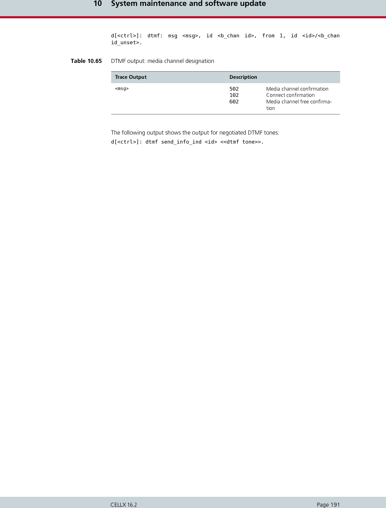
![11 Feature packagesPage 193CELLX 16.2The feature packages are modular expansion applications that provide services in addition tothose offered with the standard software. Feature packages can be activated separately or incombination with one another, so that you can design your system according to your ownneeds.The following feature packages are available:Two Stage Dialing/Callback Services (please see Chapter 11.2 on page 194)Least Cost Routing (please see Chapter 11.3 on page 200)Online Traffic Monitor (please see Chapter 11.4 on page 206)Ported Number Screening (please see Chapter 11.5 on page 213)Call recording (please see Chapter 11.6 on page 215)11.1 Activating the licenseEach feature package requires a license. Once you have ordered a feature package, you canactivate the license:The /boot/ directory of each system contains a file called license.key, which contains infor-mation on the system’s ID, the included components, which feature packages are active andthe license number:You will receive a new license.key file any time you order a new license package. Simply savethe new file, overwriting the old file, and restart the system. Example 11.1 Activating the license[IDENTIFICATION]SYSTEM: TELES.iGATESERNO: VT810011AUTOR: create Wed Sep 09 15:01:09 2006[COMPONENTS]...CARD99:11 d1 S0 PB900034...[FEATURES]PRI:MaxGSM:MaxIP:MaxVoIP:MaxSIM manager: OnDDI and call back: Offleast cost routing: Onstatistics and CDR: OnSMS gateway: Onported number screening: Offroaming: Off[SIGNATURE]00000000000license0number00000000000Deleting or making changes in the license.key file will delete any feature package licenses, causing the system to revert to the standard configuration! ii](https://usermanual.wiki/Teles-Informationstechnologien/CDMA32VOIPUS/User-Guide-1599912-Page-195.png)
![11 Feature packagesPage 194CELLX 16.211.2 Two stage dialing/callback server functionalityThis package contains money-saving features that expand the functionality of your to includeDTMF services (two stage dialing) and callback capability. It is particularly useful for companieswith employees who travel often, because it eliminates expensive roaming fees.In a two stage dialing scenario, the caller dials a number which the connects with the inte-grated DTMF platform. He then enters the destination number via DTMF. The establishes theconnection to the destination number. Callback takes place, when the initial call is released and the calling party is called back in asecond call as a response.Depending on your , various intelligent solutions as a call server are possible. The most impor-tant scenarios and properties are described here. The scenarios can also be combined to suityour needs.Announcements Two stage dialing with DTMFCallback with DTMF and OAD as callback numberCallback with DTMF and preconfigured callback numberCallback to OAD with predefined destination numberCallback with PIN and preconfigured callback numberTo indicate that the number transmitted using DTMF tones is complete, the caller can pressthe # key. Otherwise, there is a default timer set to 5 seconds, after which DTMF transmissionwill automatically end.To correct a wrong destination number, the caller can press the * key. The DTMF announce-ment is replayed and the destination number can be entered again.Activating DTMF tone recognitionThe can recognize DTMF tones and use them to initiate calls. In the pabx.cfg, enter a virtualDTMF controller, as described in Table 5.14. The corresponding Subscriber entry contains theoptions:TRANSPARENT ROUTER CHMAX[5]The 5 refers to the maximum number of simultaneous channels used for DTMF recognition.The must be restarted to activate this configuration.CDR entries for calls routed as callback with DTMF include the connection times for the A and B parties. The times are separated by a slash (/). If no connection is established to the B party, an entry recording the A party’s connection time is generated in the failed.log file.iiExample 11.2 Activating DTMF tone recognition...Controller20 = 41 DTMF...Subscriber20 = TRANSPARENT ROUTER CHMAX[5]...](https://usermanual.wiki/Teles-Informationstechnologien/CDMA32VOIPUS/User-Guide-1599912-Page-196.png)
![11 Feature packagesPage 195CELLX 16.211.2.1 AnnouncementsAn announcement can be played immediately after the connection has been established. Theannouncement’s file format must be G.711. A converter tool to convert wave files to theG.711 format is available from TELES free of charge. The announcement can be defined inthe virtual DTMF controller’s Subscriber line using the following entry in the pabx.cfg file:DTMF[<sec>,/<dir>/<file>]<sec> refers to the maximum number of seconds after which the connection to the DTMFcontroller is teared down. Please enter a time that is longer than the announcement time. Theentry <dir> refers to the directory in which the announcement file is saved. The directoryname can be boot or data. The file extension must be 711.The Subscriber line can be extended to contain up to 26 additional announcement files:DTMF[<sec>,/<dir>/<defaultfile>,/<dir>/<file_a>,/<dir>/<file_b>,...,/<dir>/<file_z>]A mapping needs to be added to the route.cfg file for every announcement to map to theport that is necessary for recognizing DTMF tones:MapAll<number>=<DTMFport>DTMF (for the default announcement file)MapAll<number>=<DTMFport>DTMFa (for file_a)...MapAll<number>=<DTMFport>DTMFz (for file_z)To stop the announcement after the entry of the first digit, a [ needs to be added behindDTMF to the respective MapAll parameter:MapAll<number>=<DTMFport>DTMF[In this example, a maximum of 5 channels can recognize DTMF tones and change them intodialing data. The default announcement is named DTMF1.711 and must be available in theboot directory. There is one additional announcement file named DTMF2.711 which mustalso be available in the boot directory. Users calling in from GSM hear the default announce-ment. After entry of the first digit, the annoucement stops. Calls coming in from analogsources trigger the announcement a stored in file_a.11.2.2 Two stage dialing with DTMFThe user dials a number in the system that is connected with the virtual DTMF controller. Hethen enters the number he wants to be connected to.Make the following entries in the route.cfg to connect a call directly:MapAll<number>=<DTMFport>DTMFMaps the calls to the DTMF port.Example 11.3 Announcements configuration in the pabx.cfgController20 = 41 DTMFSubscriber20 = TRANSPARENT ROUTER DTMF[30,/boot/DTMF1.711,/boot/DTMF2.711] CHMAX[5]Example 11.4 Announcements configuration in the route.cfgRestrict20 = IN1Restrict10 = IN2MapAllIN1 = 41DTMF[MapAllIN2 = 41DTMFa[](https://usermanual.wiki/Teles-Informationstechnologien/CDMA32VOIPUS/User-Guide-1599912-Page-197.png)
![11 Feature packagesPage 196CELLX 16.2MapAllDLA=<port>Sends all digits that have been entered as DTMF to the specified port. To prevent abuse, thefollowing entry can be made to configure a PIN before the actual call number:MapAllDLA<pin>=<port>In addition, the mapping to the DTMF port can be extended by the capital letters C to Z tosend the digits to different ports:MapAll<number>=<DTMFport>DTMFCMapAll<number>=<DTMFport>DTMFD... MapAll<number>=<DTMFport>DTMFZmust be combined with:MapAllDLC=<port>MapAllDLD=<port>...MapAllDLZ=<port>In the following example, all calls coming from GSM are connected to the virtual DTMF con-troller and the call that comes in as DTMF tones is directed to port 9. Calls to the number12345 are connected to the virtual DTMF controller and are directed to port 10.In the folllowing example, two announcement files are listed in the pabx.cfg. All calls com-ing from GSM are connected to the virtual DTMF controller and the default announcement(DTMF1.711) is played. The call that comes in as DTMF tones is directed to port 9. Calls to thenumber 12345 are connected to the virtual DTMF controller and the DTMF2.711 announce-ment is played. The call that comes in as DTMF tones is directed to port 10.Example 11.5 Two stage dialing with DTMF 1Restrict20=INMapAllIN=41DTMFMapAllDLA=9MapAll12345=41DTMFCMapAllDLC=10Example 11.6 Two stage dialing with DTMF 1 (pabx.cfg)Controller20 = 41 DTMFSubscriber20 = TRANSPARENT ROUTER DTMF[30,/boot/DTMF1.711,/boot/DTMF2.711] CHMAX[5]Example 11.7 Two stage dialing with DTMF 1 (route.cfg)Restrict20=INMapAllIN=41DTMFMapAllDLA=9MapAll12345=41DTMFaCMapAllDLC=10](https://usermanual.wiki/Teles-Informationstechnologien/CDMA32VOIPUS/User-Guide-1599912-Page-198.png)
![11 Feature packagesPage 197CELLX 16.211.2.3 Callback with DTMF and OAD as callback numberThe user calls a number to trigger callback to his calling number (OAD). After the alert tone,the system or the user hangs up and the user is called back. When he takes the call, he isrequested by announcement to enter the destination number using DTMF tones. The connec-tion to the destination number is then established.The following entries in route.cfg will initiate callback to the calling party’s number:MapAll<number>=CALLBThis entry contains the number that needs to be called to trigger callback.MapCallbackAlert=<sec>If this optional parameter is configured, the will release the trigger call after the given numberof seconds. The default value is 180. If you enter the value 1, no alert tone is sent. For all otherentries an alert tone is sent. The range of possible values is between 1 and 255.MapCallbackDelay=<sec>If MapCallbackAlert=<sec> is configured, MapCallbackDelay=<sec> is needed to definethe time between the release of the trigger call and the call back. The parameter is used toset up the call back. A callback delay of 2 to 5 seconds is recommended.MapCallbackRejCause=<cause value>If this optional parameter is configured, the trigger call to the gateway is rejected with thehere entered cause value. The default value is 16 (Normal call clearing). The values 1 - 127 arepossible. This parameter is not available for mobile ports.MapAllCB=<port>Calls back the calling party’s number via the defined port.MapAllDTMF=<DTMFport>DTMFMaps to the port that is needed for recognizing DTMF tones.MapAllDLA=<port>Sends all digits that have been entered as DTMF to the specified port.The letter “B” in CALLB can be replaced by any capital letter from C to Z to allow for differentroutings. Correspondingly, “B” in MapAllCB and “A” in MapAllDLA need to be replaced bya matching capital letter C to Z:MapAll<number>=CALLCMapAll<number>=CALLD...MapAll<number>=CALLZcorresponds with:MapAllCC=<port>MapAllCD=<port>...MapAllCZ=<port>corresponds with:MapAllDLC=<port>MapAllDLD=<port>...MapAllDLZ=<port>MapCallbackMaxDuration=<sec>This optional parameter defines the length of time that the system tries to call back the user.The entered value can be between 1 and 180. If the time limit has been exceeded, the systemterminates the call.CallbackOAD=<OAD>Configure this optional parameter in the [System] section of the pabx.cfg file to display thehere defined OAD when the gateway calls back the user. Not possible for mobile ports.](https://usermanual.wiki/Teles-Informationstechnologien/CDMA32VOIPUS/User-Guide-1599912-Page-199.png)
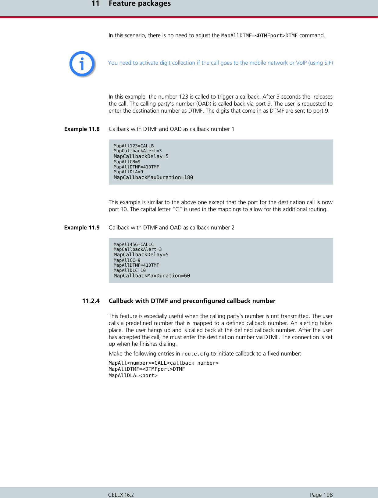
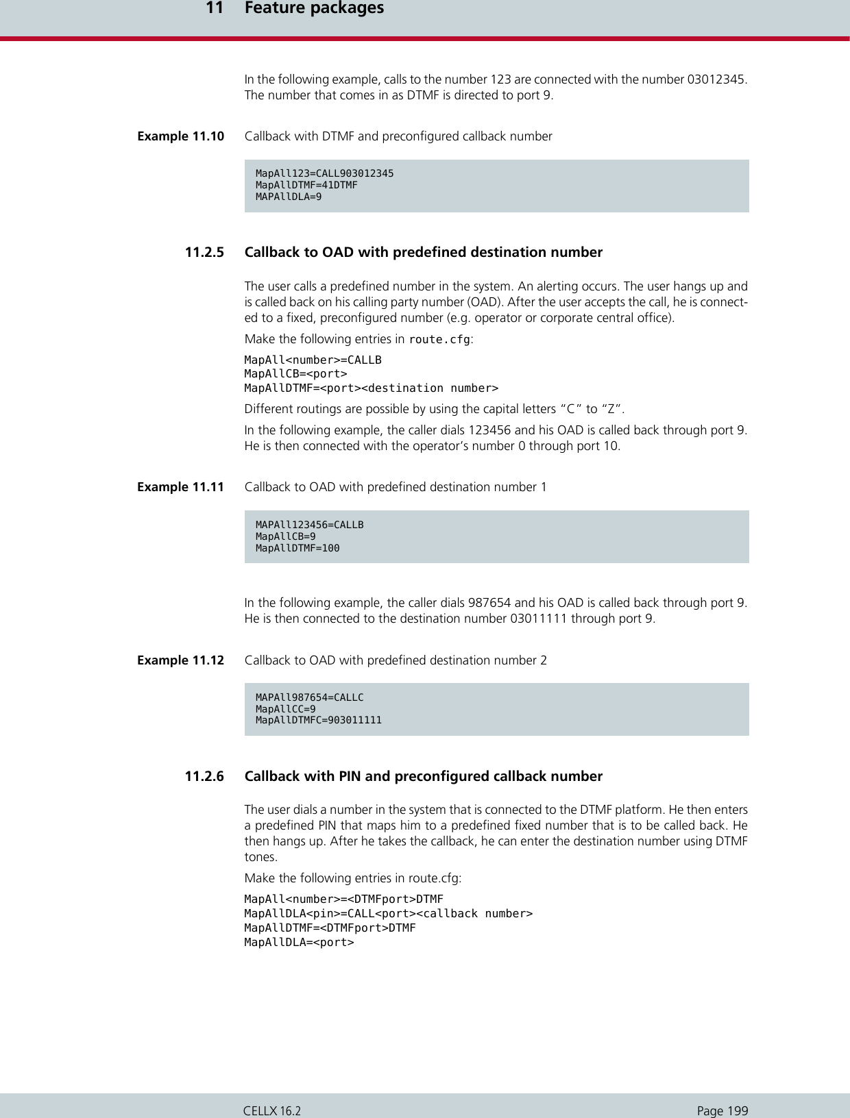
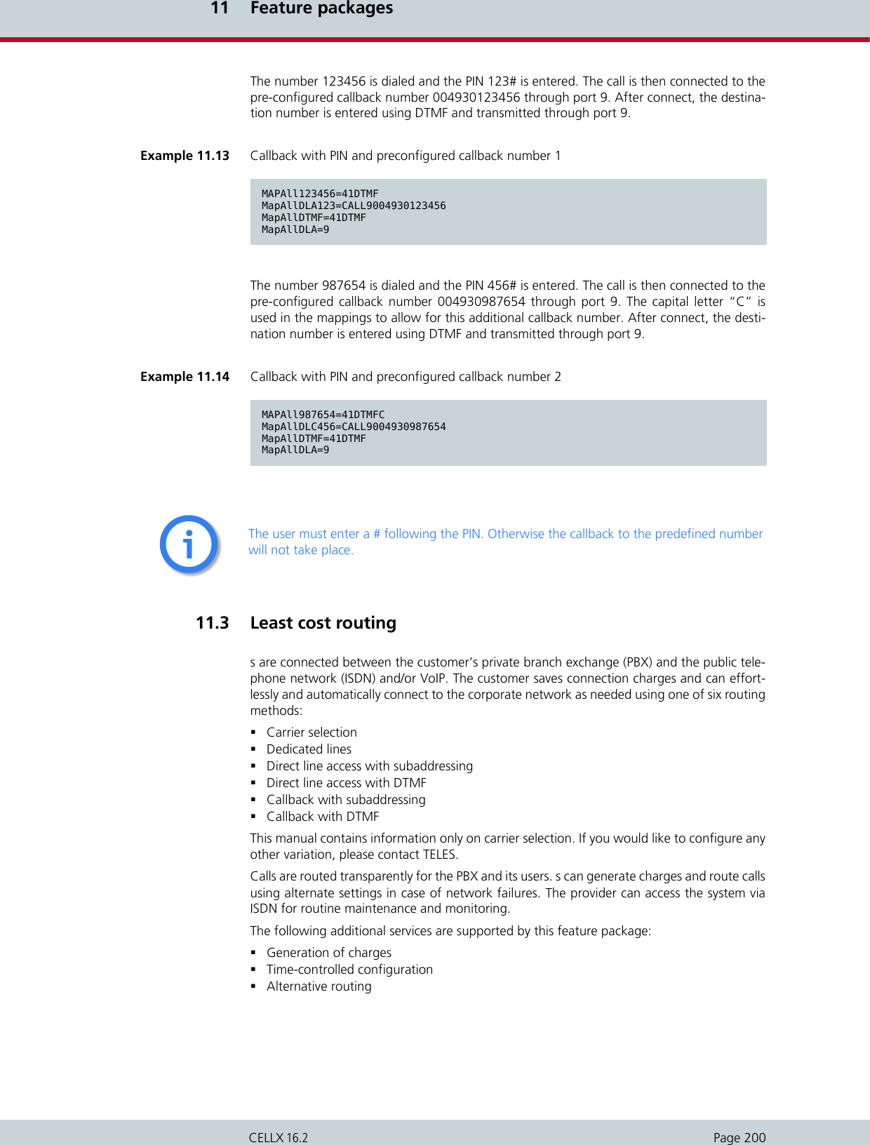
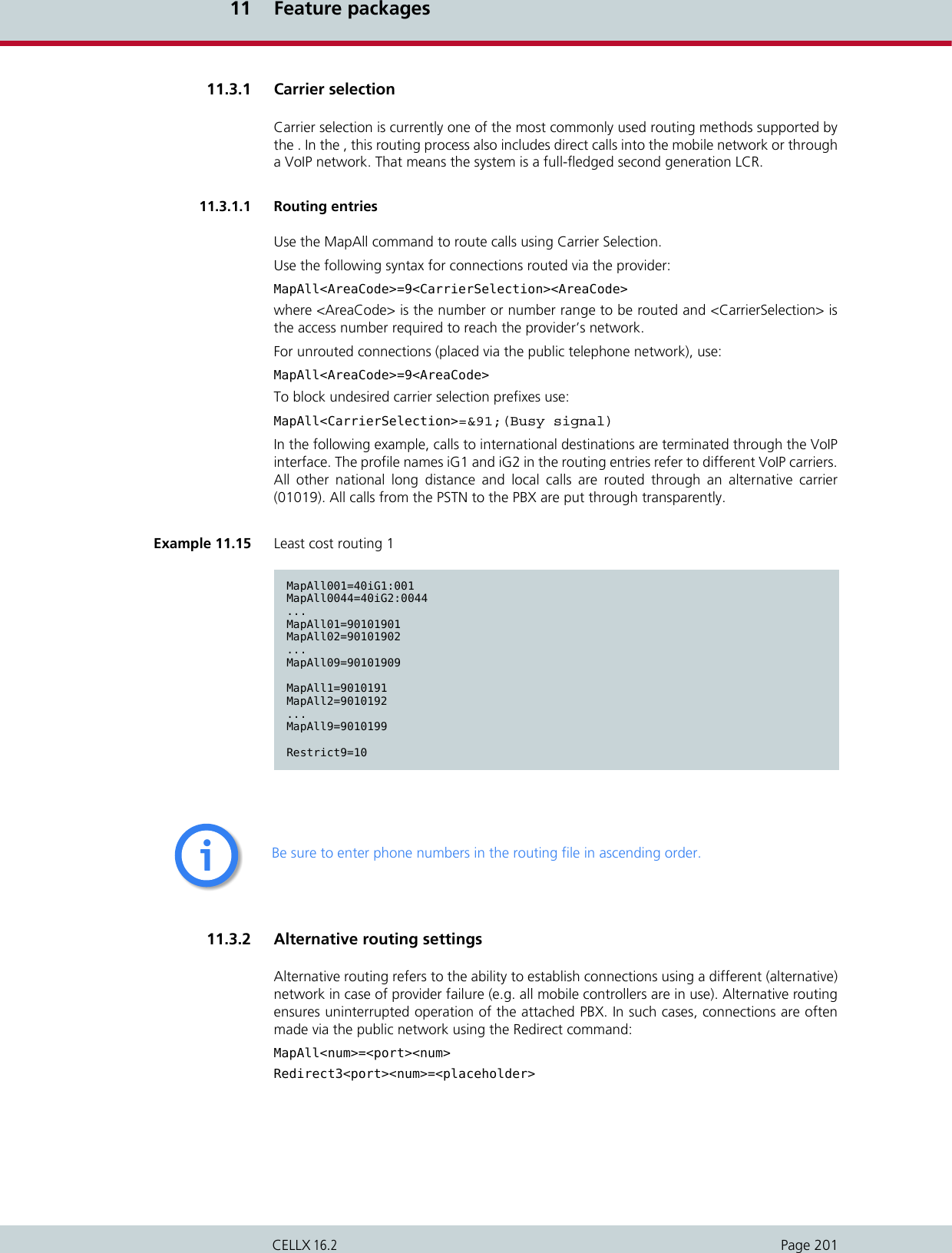
![11 Feature packagesPage 202CELLX 16.2MapAll<placeholder>=<alt port><num>11.3.3 Charge modelss can either generate charge information or transmit received charges from the public or cor-porate networks to the attached PBX. Charge simulation is achieved using variables, whichensure a great degree of flexibility for the implementation of many different charge modelsincluding:Charge units per time unitFlat rate (initial charge without time interval)Initial charge plus time intervalInitial charge plus time interval after delayTime interval and/or flat rate plus received chargesReceived charges only or no charge informationInitial toll-free period with retroactive charge generation afterwardsPrice-per-minute (with whole second accuracy)In this chapter, unit means that charge information is transmitted as a whole number value,and currency means that the charge information is sent as a currency amount (e.g. EUR3.45). The charge impulse generation options can be set for each mapping by adding charge-specific arguments to the MapAll commands, as shown below. The use of each variable is ex-plained in Table 11.1.MapAllsrc=dst time start/wait andMapCallBackOutprovsrc=dst mode time start/wait.To generate charge impulses from the first second of the call, the following parameter needsto be configured in the [System] section of the pabx.cfg file:InitialCharge=OnExample 11.16 Least cost routing 2MapAll01555=2621201555Redirect32621201555=AMapAllA=901555Table 11.1 Charge variables Variable Purposetime Determines the length of each time interval (how long each unit lasts). The value is entered in seconds and hundredths or thousandths of a second (the maximum value accepted is 655.35 seconds, 65.535 if thousandths are entered). If time is set to zero or not present no charges are generated. External charge informa-tion is passed through if received.start Sets the initial unit level. Enter a value between 0 and 127 whole units. If you want to use a flat rate, set the desired number of units here and set the wait to 255 to turn off the time interval.wait Determines the delay after which charge generation begins. Once this time has elapsed, charge impulses are sent at the interval determined by time. Enter a value between 0 and 254 seconds. 255 deactivates the charge pulse. In this case, the time variable is ignored.](https://usermanual.wiki/Teles-Informationstechnologien/CDMA32VOIPUS/User-Guide-1599912-Page-204.png)
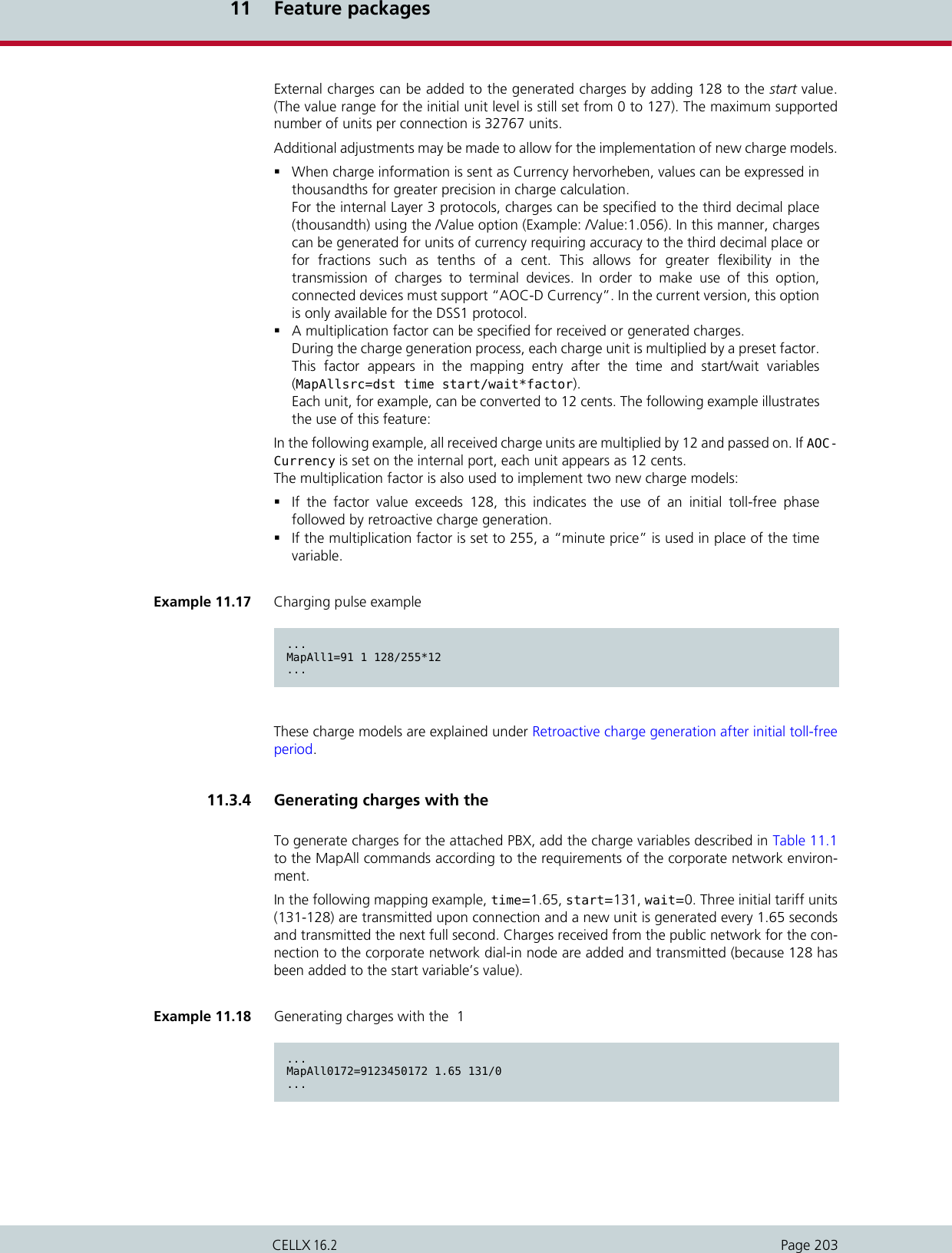
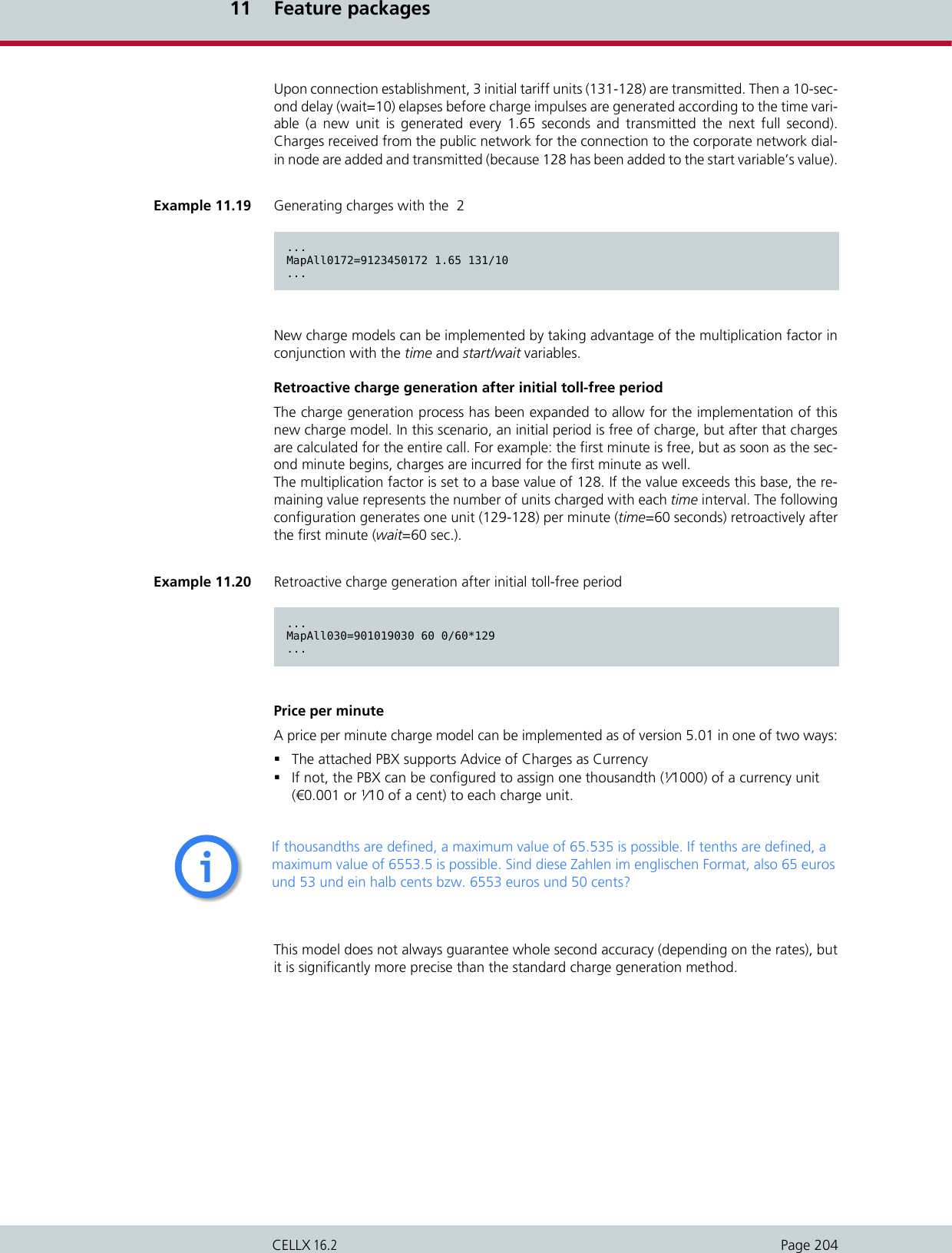
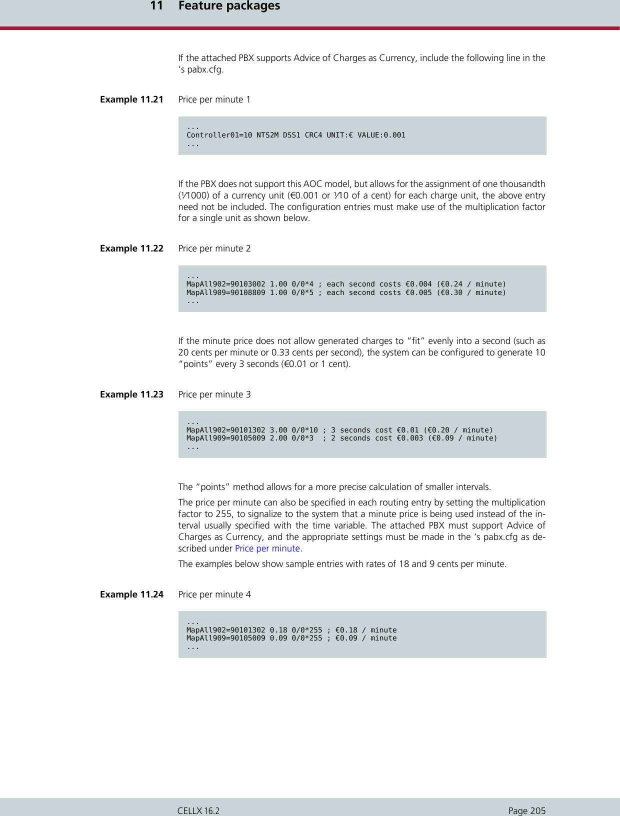
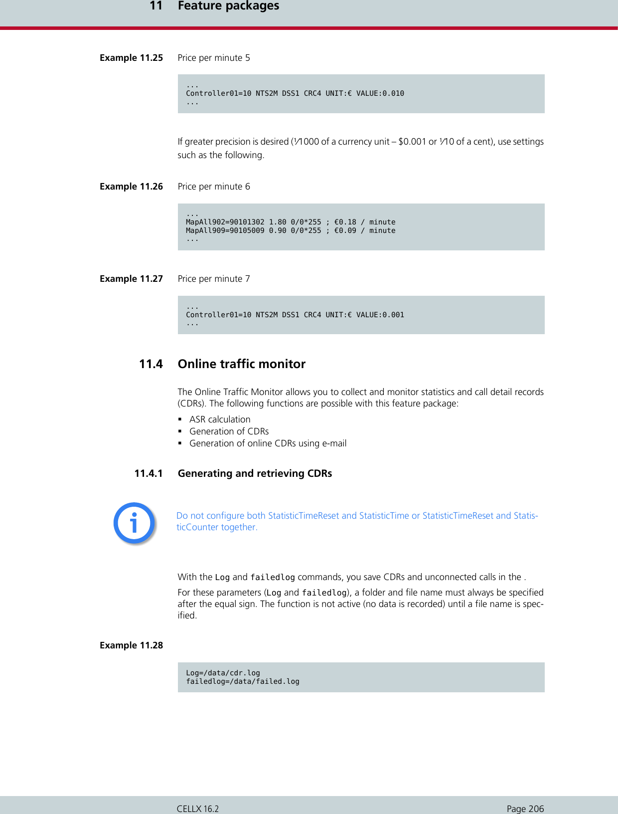
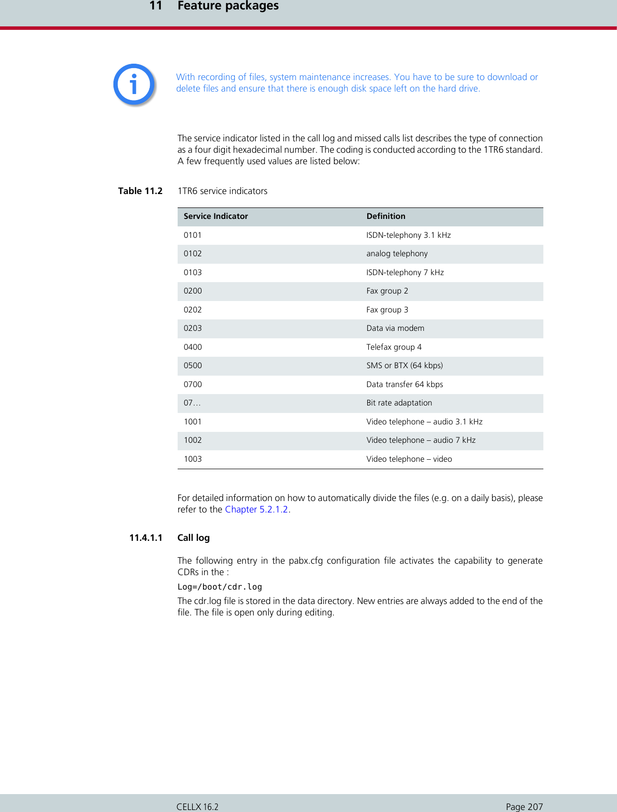
![11 Feature packagesPage 208CELLX 16.2Each line represents an outgoing call with the following information separated by commas:Sample log fileThe example below shows a sample log file.Differentiating between ports in the same trunk groupTo differentiate between ports with the same number in the CDRs, a specific node numbermust be defined. You can expand the subscriber configuration line with the keywordNODE[<no.>] for this purpose. <no.> can be a string of between 1 and 15 characters:Subscriber<xx>=... NODE[<num>]Table 11.3 Call Log Entries Column Description0Version1Start time (format DD.MM.YY-hh.mm.ss)2End time (format DD.MM.YY-hh.mm.ss)3Source. The following format applies: [node number:automatically set internal channel num-ber]4Destination. The following format applies: [node number:automatically set internal channel num-ber]5IMSI (optional)6IP logging signaling: RTP (optional)7Audio codec used (optional)8Frame size (optional)9Service indicator (cf. Chapter 11.4.1 on page 206)10 Call duration11 Cause values12 Charge from the public line (in units)13 Charge generated from the system (in units) (if configured)14 Cell ID (if mobile call)15 RSSI (if mobile call)Example 11.29 Sample log fileC1,25.11.09-10:16:20,25.11.09-10:16:27,9,111,,,,,0102,7,1f,0,,3663,10,,,C1,25.11.09-10:35:16,25.11.09-10:35:26,9,111,,,,,0102,10,1f,0,3,38922,14,,,C1,25.11.09-10:38:30,25.11.09-10:38:41,9,111,,,,,0102,11,90,0,3,38922,14,,,](https://usermanual.wiki/Teles-Informationstechnologien/CDMA32VOIPUS/User-Guide-1599912-Page-210.png)
![11 Feature packagesPage 209CELLX 16.2In the below formula, <num> consists of a four-digit number that is included in the CDR.The following example shows the pabx.cfg configuration file changed according to the for-mula.Differentiating between SIM cardsThe CDR can contain the IMSI (International Mobile Subscriber Identity), which identifies eachSIM card used.Example 11.30 Differentiating between ports in the same trunk group 1C1,25.11.09-10:16:20,25.11.09-10:16:27,[0000:01]9,[0006:01]111,,,,,0102,7,1f,0,,3663,10,,,Example 11.31 Differentiating between ports in the same trunk group 2...Subscriber00=TRANSPARENT ROUTER GSM[0000,00000,<SMSC>,1,1,1,SIM24] CHADDR ALARM NEXT NODE[0001]Subscriber01=TRANSPARENT ROUTER GSM[0000,00000,<SMSC>,1,1,1,SIM24] CHADDR ALARM NEXT NODE[0002]Subscriber02=TRANSPARENT ROUTER GSM[0000,00000,<SMSC>,1,1,1,SIM24] CHADDR ALARM NEXT NODE[0003]Subscriber03=TRANSPARENT ROUTER GSM[0000,00000,<SMSC>,1,1,1,SIM24] CHADDR ALARM NEXT NODE[0004]Subscriber04=TRANSPARENT ROUTER GSM[0000,00000,<SMSC>,1,1,1,SIM24] CHADDR ALARM NEXT NODE[0005]Subscriber05=TRANSPARENT ROUTER GSM[0000,00000,<SMSC>,1,1,1,SIM24] CHADDR ALARM NEXT NODE[0006]Subscriber06=TRANSPARENT ROUTER GSM[0000,00000,<SMSC>,1,1,1,SIM24] CHADDR ALARM NEXT NODE[0007]Subscriber07=TRANSPARENT ROUTER GSM[0000,00000,<SMSC>,1,1,1,SIM24] CHADDR ALARM NEXT NODE[0008]Subscriber08=TRANSPARENT ROUTER GSM[0000,00000,<SMSC>,1,1,1,SIM24] CHADDR ALARM NEXT NODE[0009]Subscriber09=TRANSPARENT ROUTER GSM[0000,00000,<SMSC>,1,1,1,SIM24] CHADDR ALARM NEXT NODE[0010]Subscriber10=TRANSPARENT ROUTER GSM[0000,00000,<SMSC>,1,1,1,SIM24] CHADDR ALARM NEXT NODE[0011]Subscriber11=TRANSPARENT ROUTER GSM[0000,00000,<SMSC>,1,1,1,SIM24] CHADDR ALARM NEXT NODE[0012]Subscriber12=TRANSPARENT ROUTER GSM[0000,00000,<SMSC>,1,1,1,SIM24] CHADDR ALARM NEXT NODE[0013]Subscriber13=TRANSPARENT ROUTER GSM[0000,00000,<SMSC>,1,1,1,SIM24] CHADDR ALARM NEXT NODE[0014]Subscriber14=TRANSPARENT ROUTER GSM[0000,00000,<SMSC>,1,1,1,SIM24] CHADDR ALARM NEXT NODE[0015]Subscriber15=TRANSPARENT ROUTER GSM[0000,00000,<SMSC>,1,1,1,SIM24] CHADDR ALARM NEXT NODE[0016]...Example 11.32 Differentiating between SIM cards 1C1,25.11.09-10:35:16,25.11.09-10:35:26,9,111,123456789123451,,,,0102,10,1f,0,3,38922,14](https://usermanual.wiki/Teles-Informationstechnologien/CDMA32VOIPUS/User-Guide-1599912-Page-211.png)
![11 Feature packagesPage 210CELLX 16.2The following example shows the pabx.cfg configuration file changed according to the for-mula.Activating peer data for VoIP callsTo generate a VoIP-call CDR entry that includes IP addresses for the remote device’s signalingand voice data, audio codec and frame size, the entry VoipIpLogging=Yes must be includedin the VoIP profile. The following entry shows the route.cfg configuration file changed according to the for-mula.The following CDR entry includes IP addresses for signaling and voice data, audio codec andframe size.Example 11.33 Differentiating between SIM cards 2...Subscriber04=TRANSPARENT ROUTER GSM[0000,00000,<SMSC>,1,1,1,SIM4,IMSI] CHADDR ALARM NEXTSubscriber05=TRANSPARENT ROUTER GSM[0000,00000,<SMSC>,1,1,1,SIM4,IMSI] CHADDR ALARM NEXTSubscriber06=TRANSPARENT ROUTER GSM[0000,00000,<SMSC>,1,1,1,SIM4,IMSI] CHADDR ALARM NEXTSubscriber07=TRANSPARENT ROUTER GSM[0000,00000,<SMSC>,1,1,1,SIM4,IMSI] CHADDR ALARM NEXT...Example 11.34 Activating peer data for VoIP calls 1[Voip:DF]VoipDirection=IOVoipPeerAddress=192.168.0.2VoipIpMask=0xffffffffVoipCompression=g729 g711a t38VoipMaxChan=30VoipSilenceSuppression=Yes VoipSignalling=0VoipTxM=4VoipIPLogging=YesExample 11.35 Activating peer data for VoIP calls 2C1,24.11.09-16:52:20,24.11.09-16:52:22,401419,9777,,172.20.25.103:172.20.25.103,G711a,20,0101,2,10,0,,,11](https://usermanual.wiki/Teles-Informationstechnologien/CDMA32VOIPUS/User-Guide-1599912-Page-212.png)
![11 Feature packagesPage 211CELLX 16.2CDRs for callback and two stage callsIn the case of CDR entries for Two stage dialing/Callback calls, the beginning and endingtimes for the first call leg is always used as the call time. The call time in seconds appears firstfor the first leg, followed by a slash and the connection time for the second leg.11.4.1.2 Missed calls listAll incoming calls that are not connected can be recorded in a list to facilitate return calls.Recording is activated using the failedlog=<name> entry in the pabx.cfg. Specify a filename, e.g. failedlog=failed.log. Once this setting is made, recording begins at once.Each line represents an unaccepted incoming call with the following information separatedby commas:Example 11.36 CDRs for callback and two stage callsC1,24.11.09-17:15:29,24.11.09-17:15:57,[0002:01]CB,[0008:01]DLA,,172.20.25.103:172.20.25.103,G711a,20,0102,28/3,90,0,,,To avoid sending these values as the reason for call teardown, translate the cause values to standard values Chapter 8.14iiTable 11.4 Failed log entries Column Description0Version1Start time (format DD.MM.YY-hh.mm.ss)2 Source. The following format applies: [node number:automatically set internal channel num-ber]3Destination. The following format applies: [node number:automatically set internal channel num-ber]4IMSI5IP logging signaling: RTP6 Audio codec used7Frame size8 Service indicator (cf. Chapter 11.4.1 on page 206)9Cause values10 Call duration (if the call does not result in an Alerting, the entry will be -1)11 Number of call attempts](https://usermanual.wiki/Teles-Informationstechnologien/CDMA32VOIPUS/User-Guide-1599912-Page-213.png)
![11 Feature packagesPage 212CELLX 16.2The example below shows a sample failed log file.The reason the connection could not be established is specified using DSS1 codes:91 – (user busy)ff – call not answered (disconnected by calling party)When callback with DTMF is configured and no connection is established to the B subscriber,an entry recording the A subscriber’s connection time is generated in the failed.log file.The CDR contains the IP addresses for signaling and voice data. The first IP address is the sig-naling address and the second one is the RTP address.The IMSI is written behind the IP ad-dresses.12 Cell ID13 RSSITable 11.4 Failed log entries (continued)Column DescriptionExample 11.37 Sample failed log 1V1,24.11.09-16:13:08,[0006:01]IN,[0008:01]GSM,123456789123456,,,,0101,92,-1,1,34193,9V1,24.11.09-16:33:34,[0006:01]IN,[0008:01]GSM,123456789123456,,,,0101,92,-1,1,34193,12V1,24.11.09-16:35:19,[0006:01]IN,[0008:01]GSM,123456789123456,,,,0101,92,-1,1,34193,11V1,24.11.09-16:35:59,[0006:01]IN,[0008:01]GSM,123456789123456,,,,0101,92,-1,1,34193,11V1,24.11.09-16:37:29,[0006:01]IN,[0008:01]GSM,123456789123456,,,,0101,92,-1,1,34193,11V1,24.11.09-16:39:17,[0006:01]IN,[0008:01]GSM,123456789123456,,,,0101,ff,7,1,34193,11Example 11.38 Sample failed log 2V1,24.11.09-16:39:17,[0006:01]IN,[0008:01]GSM,123456789123456,,,,0101,ff,7,1,34193,11Example 11.39 Sample failed log 3V1,24.11.09-16:52:20,24.11.09-16:52:22,[0008:01]401419,[0006:01]IN777,262032441017556,172.20.25.103:172.20.25.103,G711a,20,0101,2,10,0,,34193,11](https://usermanual.wiki/Teles-Informationstechnologien/CDMA32VOIPUS/User-Guide-1599912-Page-214.png)
![11 Feature packagesPage 213CELLX 16.2In the case of missed-call entries for Two stage dialing/Callback calls, dur is the connectiontime for the first leg.11.4.1.3 Sending CDRs via e-mailWith an appropriate configuration, you can send corresponding CDRs of outgoing and in-coming calls as e-mail. Bear in mind that the mail server must be configured in the [Mail] sec-tion of the pabx.cfg, as described in Chapter 5.2.2. The sender is given as cdr and thesystem’s name appears in the subject box. The text box contains the CDR information accord-ing to the format for the entry in Log=/data/cdr.log @<account> @<domain>. A space mustappear between cdr.log and @<account>; @<domain> is optional. You can also send CDRentries via e-mail to an e-mail recipient. Enter an @ sign to send each CDR entry as e-mail.If you replace the first @ sign with an !, the present cdr.log will be sent whenecver a new oneis generated.11.5 Ported number screeningPorted number screening is a very useful functionality to avoid high routing costs for numbersthat have been ported to another network operator.Number portabilty refers to the ability to transfer either an existing landline or mobile tele-phone number to another network operator. This way telecommunications subscribers canchange operators without having to change their telephone numbers. Routing ported num-bers, however, can become very cost intensive due to differences in tariffs.With ported number screening, an external database is queried to find out if a number hasbeen ported. Either use the iMNP for querying the external database or query the databasedirectly. The iMNP is a proxy that remembers the database information for a defined periodof time and renews the query to the external database only after that period has passed. Sinceevery query to the external database costs money, the iMNP helps to reduce querying costs.The qery result is used in a routing to route the call via the right network operator. Example 11.40 Sample failed log 4V1,25.11.09-14:11:10,[0002:01]CB,DLA,,,,,0102,11,14,1,,Example 11.41 Sending CDRs via e-mail 1Log=/data/cdr.log @bob@example.comExample 11.42 Sending CDRs via e-mail 2Log=/data/cdr.log daily 60 5 !bob@example.com](https://usermanual.wiki/Teles-Informationstechnologien/CDMA32VOIPUS/User-Guide-1599912-Page-215.png)
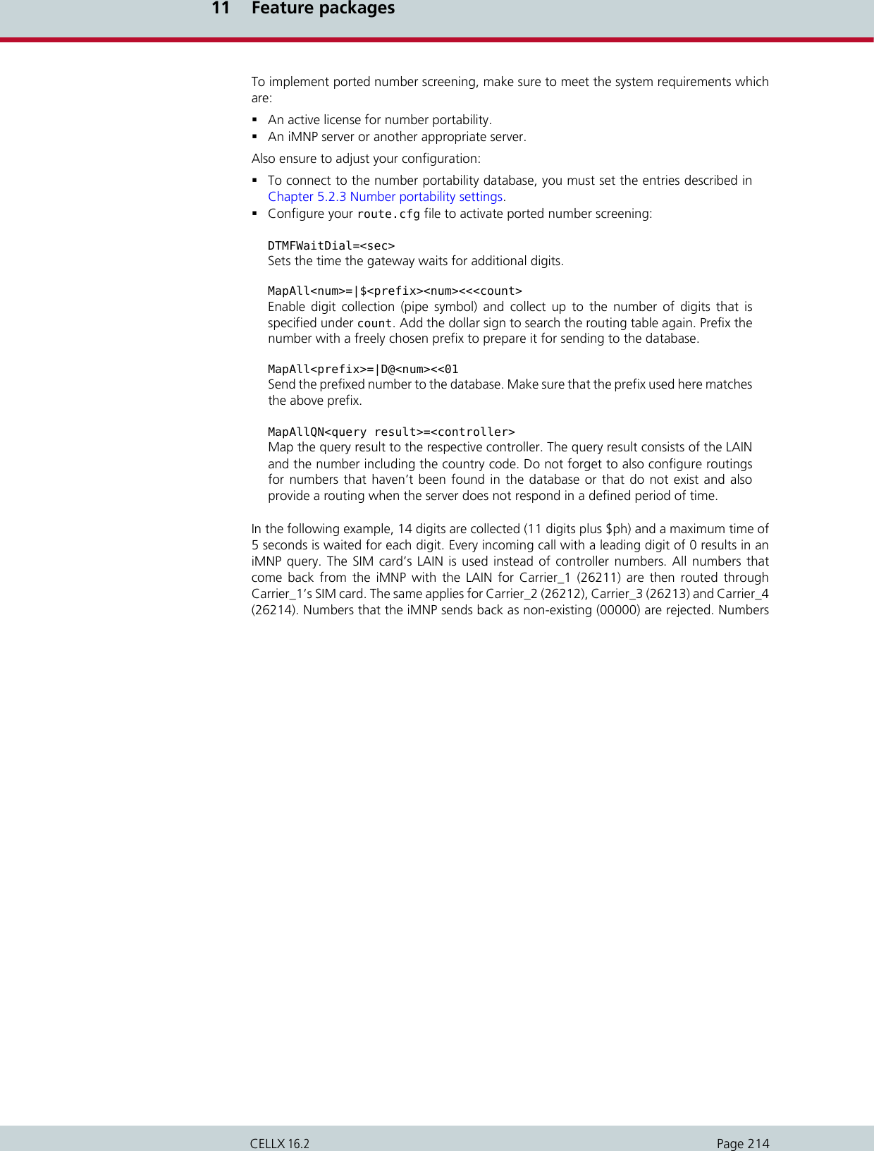
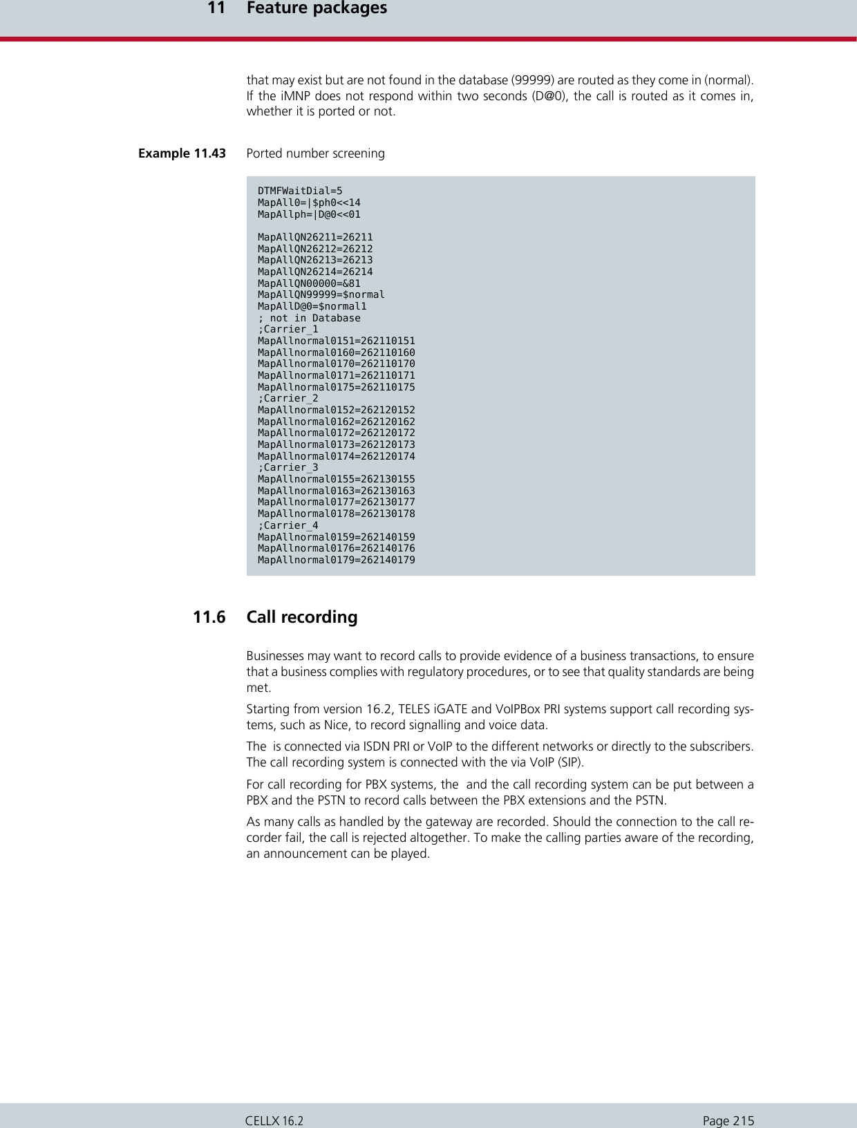
![11 Feature packagesPage 217CELLX 16.2The VoIP profile that is needed for the signalling messages contains the following parameters:To attach the gateway to the call recorder, an additional entry must be configured in the Sys-tem section of the pabx.cfg file:An RTP specific VoIP profile, if needed, is configured in the route.cfg file. Its name mustcomply with the entry in the second VoipNiceMRA parameter. This VoIP profile must containa VoIPCompression parameter which needs to match the codec used for actual calls. All oth-er parameters are configured as described in the VoIP profile above:Table 11.5 VoIP profile for signalling messages (route.cfg) Parameter Description[VOIP:name of VoIP profile for sig-nalling mesages]Enter here the name of the VoIP profile. The profile has to have the same name as the VoipNiceMRA pa-rameter in the pabx.cfg file.VoipDirection=Out For communication with the call recorder, the direc-tion needs to be “out”.VoipPeerAddress=<IP address of call recorder>Enter here the IP address of the call recorder (or, al-ternatively, the domain name).VoipProxy=<IP address of proxy> Optional. Enter the IP address to which you want to send the INVITE, if the INVITE is not to be sent to the IP configured in VoipPeerAddress.VoipSignalling=<num> Enter 1 for SIP signalling via udp, 2 for SIP via tcp , or 3 for SIPS.VoipOwnAddress=<IP address of gate-way>Optional. Enter here the IP address or domain name as requested by the peer. Table 11.6 VoipNiceMRA parameter for signalling messages (pabx.cfg)Parameter DescriptionVoipNiceMRA=<name of VoIP profile for signalling mesages>The name entered here must be the name of the VoIP profile for signalling messages.Table 11.7 VoIP profile for RTP data (route.cfg) Parameter Description[VOIP:name of VoIP profile for RTP data]Enter here the name of the VoIP profile. The profile has to have the same name as the VoipNiceMRA pa-rameter in the route.cfg file.VoipDirection=Out For communication with the call recorder, the direc-tion needs to be “out”.VoipPeerAddress=<IP address of call recorder>Enter here the IP address of the call recorder (or, al-ternatively, the domain name).](https://usermanual.wiki/Teles-Informationstechnologien/CDMA32VOIPUS/User-Guide-1599912-Page-219.png)
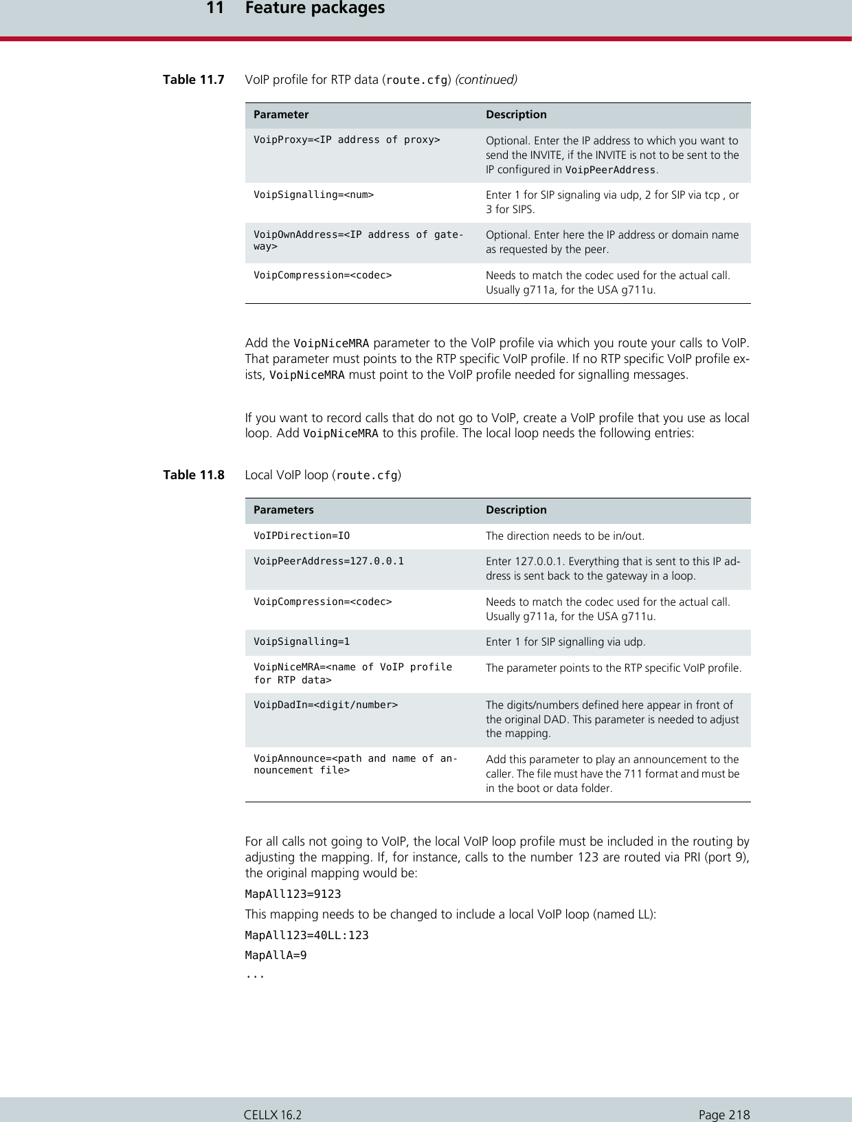
![11 Feature packagesPage 219CELLX 16.2[Voip:LL]VoipDadIn=AFor calls to the DAD 123 the MapAll parameters are searched, MapAll123=40LL:123 match-es the search criteria. As configured in the MapAll parameter, the call is then sent on a localVoIP loop through port 40 and the LL profile. In this profile, the original DAD is prefixed withthe capital letter A as configured in VoipDadIn=A. The local loop sends back the call to thegateway. The MapAll parameters are searched again, a match is found here: MapAllA=9. Thismapping sends the call to the PRI port 9.If you want to play an announcement to the caller before connecting the call to the destina-tion, add VoipAnnounce=<path and name of announcement file> to the local VoIP loop,or, for calls going to VoIP, to the VoIP profile through which you send the call.The complete example can be found below. The local VoIP loop is named LL. There is onlyone VoIP profile used for the communication with the call recorder, named call_recorder.Both VoipNiceMRA parameters point to this profile. Calls to the PRI port 9 are sent througha local VoIP loop to enable call recording. An announcement is played to the caller.Example 11.44 Call recording (pabx.cfg)VoipNiceMRA=call_recorderExample 11.45 Call recording (route.cfg) MapAll123=40LL:123MapAllA=9...[Voip:LL]VoipDirection=IOVoipPeerAddress=127.0.0.1VoipCompression=g711aVoipSignalling=1VoipNiceMRA=call_recorderVoipDadIn=AVoipAnnounce=/boot/announcement.711[Voip:call_recorder]VoipDirection=OUTVoipPeerAddress=172.20.27.161VoipProxy=172.20.25.7VoipCompression=g711aVoipSignalling=1VoipOwnAddress=ext2000@somelocation.com](https://usermanual.wiki/Teles-Informationstechnologien/CDMA32VOIPUS/User-Guide-1599912-Page-221.png)
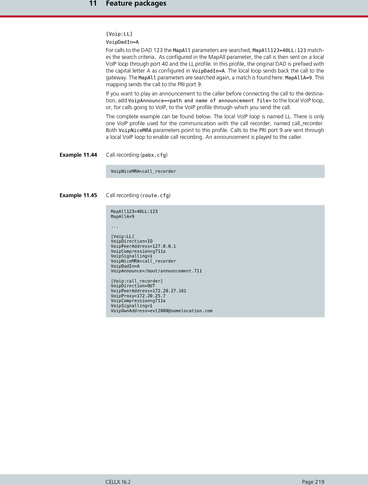
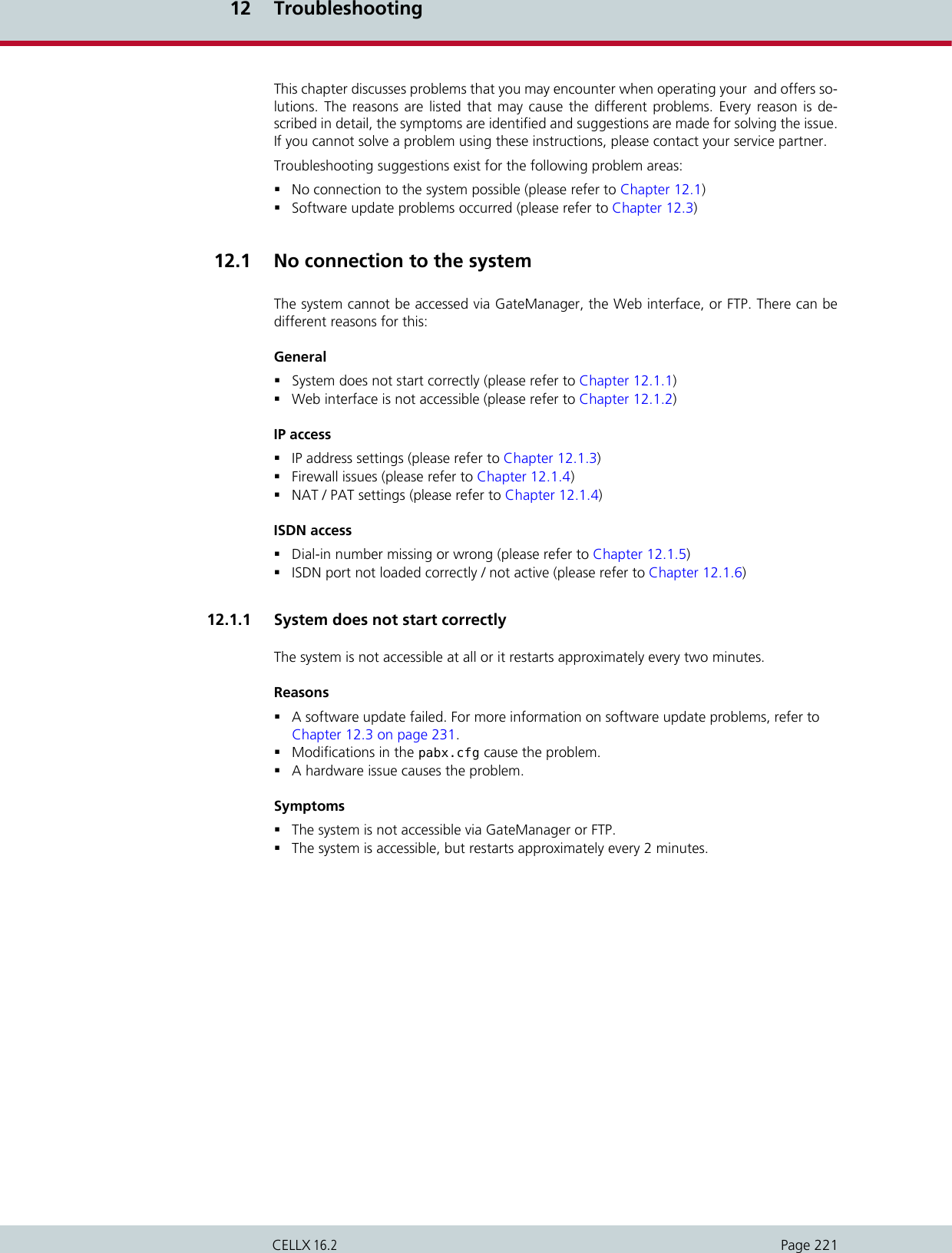
![12 TroubleshootingPage 222CELLX 16.2SolutionMake sure that FTP is allowed in your network.Check whether you have access to the system using FTP.If you cannot access your , the operating system is no longer accessible. In that case youneed to contact your service partner for help.If the system can be accessed but restarts approximately every two minutes, try to solvethe problem by taking the following actions:– Connect to your via FTP.– Change to the boot directory.– Delete or rename the *.tz1 file. This stops the recurring reboot of the system andgives you time to search for the problem.–Check the pabx.cfg for modifications that may have caused the problem andchange or replace the file. Make sure that the [System] section is not missingand check the Controller entry for the correct numberings, matching Con-troller and Subscriber entries, and the correct hardware settings.– Upload the system-specific *.tz1 file again or change it back to its real name.– Restart the system:by resetting the power orby going to your FTP client’s command line interpreter and selecting restart.This option depends on your FTP client’s functionality. For a description of theFTP commands, please refer to Table 4.8, “FTP commands” on page 34.If none of the above solutions solve the problem, there might be a hardware issue thatcauses the system behavior. Please contact your service partner for help in handling apossible hardware problem. Please do not open your on your own as you would thuslose warranty. 12.1.2 Web interface is not accessibleYour can be accessed through a web interface which requires installation in addition to themandatory system files. Mismatches between system version and the version of the web in-terface, missing web interface files or no permission for port 80 are most likely the reasonwhy access to a system through the web interface fails.ReasonsThe system is not accessible through the web interface because the required files werenot installed.The system cannot be accessed through the web interface because the required versiondoes not match the system version.The system cannot be accessed through the web interface because you don’t havepermission to access port 80 (the firewall is blocking).SymptomsThere is no connection to the system through the web interface.SolutionIn the GateManager, go to the boot directory and check if the httpd.izg andhttpd.tz2 files exist. If not, update your software. Follow the steps described inchapter 10.3, “Software update”.If these files exist but if the system still cannot be accessed through the web interface,check if there is a mismatch between the system version and the version of the files forthe web interface and replace the web interface files by matching ones. To do that,follow the steps described in chapter 10.3, “Software update”.If the problem persists, check if port 80 is blocked by your firewall. For detecting firewallproblems, please see also12.1.4, “Firewall issues and NAT / PAT settings” on page 223.](https://usermanual.wiki/Teles-Informationstechnologien/CDMA32VOIPUS/User-Guide-1599912-Page-224.png)
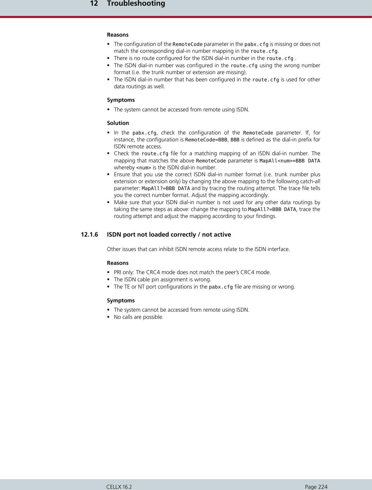
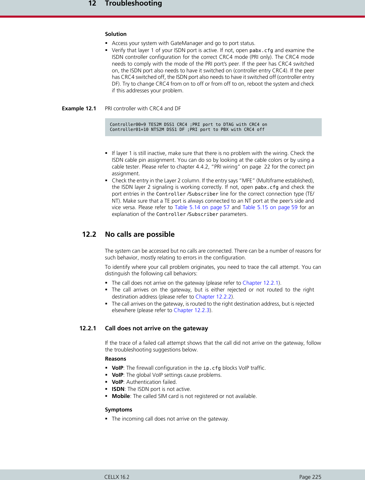
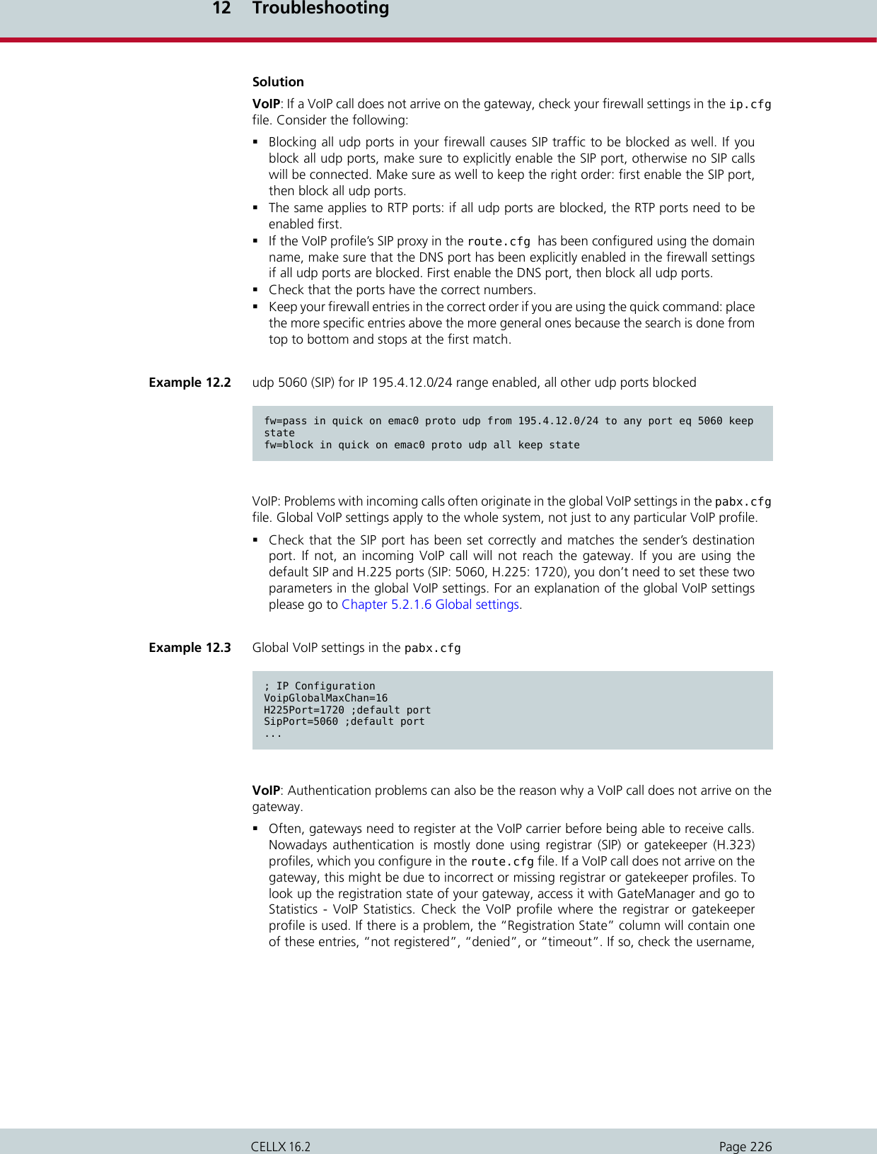
![12 TroubleshootingPage 227CELLX 16.2password and registrar IP or gatekeeper IP in the associated profile. You can likewiselook up the registration state in the protocol.log file. For an explanation of how toconfigure gatekeeper profiles please see Chapter 5.3.3 Gatekeeper profiles. To look upinformation on the registrar profile please read Chapter 5.3.4 Registrar profiles.ISDN: If an incoming ISDN call does not arrive on the gateway, check the port status (usingGateManager) and the configuration of the ISDN ports in the pabx.cfg.Access your system with GateManager and go to port status.Verify that layer 1 of your ISDN port is active. If not, open pabx.cfg and examine theISDN controller configuration for the correct CRC4 mode (PRI only). For an explanation,please see Chapter 12.1.6 ISDN port not loaded correctly / not active.If layer 1 is still inactive, check the wiring of the ISDN cable. For an explanation, go toChapter 12.1.6 ISDN port not loaded correctly / not active.If you see in the GateManager that layer 1 is active but layer 2 does not show the entry“MFE” (Multiframe established), check the port configuration in the pabx.cfg file.Refer to Chapter 12.1.6 ISDN port not loaded correctly / not active for details.Example 12.4 Gatekeeper profile[Gatekeeper:GK1]RasPort=1719OwnRasPort=1719RasId=iGATE01RasPrefix=01555 01556 01444 01445GkId=GKGkAdd=192.168.0.10GkPwd=GkTtl=300GkMaxChan=30GkDynMaxChan=YesExample 12.5 Registrar profile[Registrar=reg]RegId=office.teles.deRegUser=4930399280RegPwd=123456789RegProxy=<ip adr.>RegPing=20RegExpires=3600](https://usermanual.wiki/Teles-Informationstechnologien/CDMA32VOIPUS/User-Guide-1599912-Page-229.png)
![12 TroubleshootingPage 229CELLX 16.2go to Chapter 5.3.1.2 MapAll to learn about the correct configuration of the MapAllcommand. For information on VoIP profiles, please read Chapter 5.3.2 VoIP profiles.Mobile / VoIP / ISDN / analog: A license issue can be the reason why a call is rejectedby the gateway. Access your system using GateManager and check which licenses areavailable under General, and - in the case of trial licenses - what day they expire. Iflicenses are missing, they are not listed in the Licenses field. The date in License Termindicates if trial licenses have already expired. If the Licenses entry is empty, this meansthat you are either using the wrong software or the wrong license key. In addition, thelicense.key file tells you about possible LAIN restrictions. Licenses can be restrictedby LAIN, so that gateways can only be used in certain countries and / or with certainmobile operators. Contact your service partner for help.Mobile: In the configuration for mobile ports, missing CHADDR parameters often causeproblems with outgoing calls. If you are routing by LAIN, check that CHADDR exists inyour Subscriber settings. Also check that the corresponding mappings include thecorrect LAIN instead of the address port (trunk group). Access your system usingGateManager and check which trunk group or LAIN is displayed in the Address columnunder port status. Modify the pabx.cfg or route.cfg files, if needed. For a descriptionof the Subscriber configuration please read Chapter 5.2.1.5 Subscribers.Example 12.6 LAIN configuration in the pabx.cfg...Controller06=20 GSM...Subscriber06=TRANSPARENT ROUTER GSM[0000,00000,+000000,1,1,1,SIM4,IMSI,BAND(6)] CHADDR ALARM NODE[0006]...Example 12.7 Corresponding mapping by LAIN in the route.cfgMapAll0172=262070172](https://usermanual.wiki/Teles-Informationstechnologien/CDMA32VOIPUS/User-Guide-1599912-Page-231.png)
![12 TroubleshootingPage 230CELLX 16.2VoIP: Missing or incorrect VoIP profiles cause problems with incoming or outgoing VoIP calls.The gateway receives the call but refuses to route it. For an explanation of the configurationof VoIP profiles please read Chapter 5.3.2 VoIP profiles.In the case of an incoming call, the system searches the route.cfg file for a VoIPprofile which matches the incoming VoIP call. That VoIP profile must be defined forincoming, or incoming and outgoing calls (VoipDirection=In orVoipDirection=IO). Check that the peer address and the VoIP mask match the IPrange from which you expect VoIP calls. Verify that the codecs which have been enteredin the VoipCompression parameter match the peer’s codec. To look up the codecoffered by the peer, you need to run a layer 2 / layer 3 trace.In the case of an outgoing call, set VoipDirection=Out or VoipDirection=IO. TheVoipPeerAddress parameter must contain the IP address to which you send VoIPtraffic. The VoipIpMask parameter is not needed. Again, the VoipCompressionparameter needs to match the peer’s codecs.In all cases, ensure to put the profile name in square brackets.In the following example, the gateway receives a call from the IP 195.4.13.14. There isonly one VoIP profile for incoming VoIP calls in the gateway’s route.cfg file. The VoIPprofile’s VoipPeerAddress parameter is 195.4.13.0. The VoipIPMask parametercontains the value 0xfffffff8 which translates into the subnet mask255.255.255.248. This means that the IP addresses 195.4.13.0 to 195.4.13.7 can sendcalls. The IP address 195.4.13.14 which actually sent the call is not inside this range.The call is thus rejected by the gateway.To allow for calls coming from 195.4.13.14 the VoipIpMask parameter needs to bechanged, as shown in the following example. The IP addresses 195.4.13.0 to195.4.13.15 can now send VoIP traffic.Example 12.8 Calls from 195.4.13.14 rejected[Voip:GW1]VoipDirection=InVoipPeerAddress=195.4.13.0VoipIpMask=0xfffffff8VoipCompression=g711u g711aVoipSilenceSuppression=YesVoipSignalling=1VoipFaxTransport=1VoipMaxChan=120VoipTxM=2VoipMediaWaitForConnect=ToneVoipProgress=2Example 12.9 Calls from 195.4.13.14 accepted[Voip:GW2]VoipDirection=InVoipPeerAddress=195.4.13.0VoipIpMask=0xfffffff0VoipCompression=g711u g711aVoipSilenceSuppression=YesVoipSignalling=1VoipFaxTransport=1VoipMaxChan=120VoipTxM=2VoipMediaWaitForConnect=ToneVoipProgress=2](https://usermanual.wiki/Teles-Informationstechnologien/CDMA32VOIPUS/User-Guide-1599912-Page-232.png)