Tele Radio T60TX-08 SECURITY TRANSMITTER User Manual USERS MANUAL
Tele Radio AB SECURITY TRANSMITTER USERS MANUAL
USERS MANUAL
SE
NLES
FR
DE
GB
US NO DK
CONTENTS / ENGLISH
xx Important Information
xx Codes
xx Placement of the Aerial and Receiver
xx The Transmitter
xx Programming the Receiver
xx Co-programming the Transmitter and Receiver
xx Trouble Shooting Chart
xx Service and Support
xx Coding Tables 1-10, Appendix A
xx Coding Tables 0-15, Appendix B
xx Coding Tables 460-93, Appendix C
xx Connecting the receiver – see Appendix D
IMPORTANT!
In order to make optimal use of your system, it is important that
you take the time to read through this manual before you begin
to install/program your equipment.

DK
SE
NL
ES
FRDE
GB
US NO
SE
NLES
FR
DE
GB
US NO DK
GENERAL INFORMATION
The system works at the frequency 433.92MHz and uses frequency modu-
lation, commonly referred to as FM. The main benet of using FM instead of
the more common AM (amplitude modulation) is that FM is less sensitive
to the electrical interference generated by computers, electric motors, etc.
Objects positioned between the transmitter and receiver aerial, especially
large metal objects (think about the reinforcement rods in concrete walls),
can affect the range in a very unpredictable manner, depending on how the
radio signals spread.
The effect of other radio transmitters operating on the same frequency
in the vicinity also affects the range. Due to these factors, it is difcult to
provide any general advice other than that if there is a free line of visibility
between the transmitter and the receiver the range with an optimal signal
should be the best.
The normal range for the transmitter in an interference-free environment
is about 50-100m.
DK
SE
NL
ES
FRDE
GB
US NO
SE
NLES
FR
DE
GB
US NO DK
T60 CODES
T60RX-0XYZL
The transmitter and receiver that are to be used together must be coded
together before use. The T60 system has two different types of codes:
Adjustable codes:
All transmitters are equipped with a code switch that consists of 10 three-
position switches, which makes it possible to choose freely among 59,049
different codes.
Fixed individual code:
Each transmitter is supplied with a xed individual code that cannot be
changed.
“Learning” the codes:
In the 460 system, the transmitter and receiver are coded together
through a self-instruction process, in other words, the receiver ”learns” the
transmitter’s code. You can have the receiver learn only the adjustable code
or both the adjustable and xed individual code.
Compatible with the 460 system
The T60 system is compatible with Tele Radio’s 460 system.
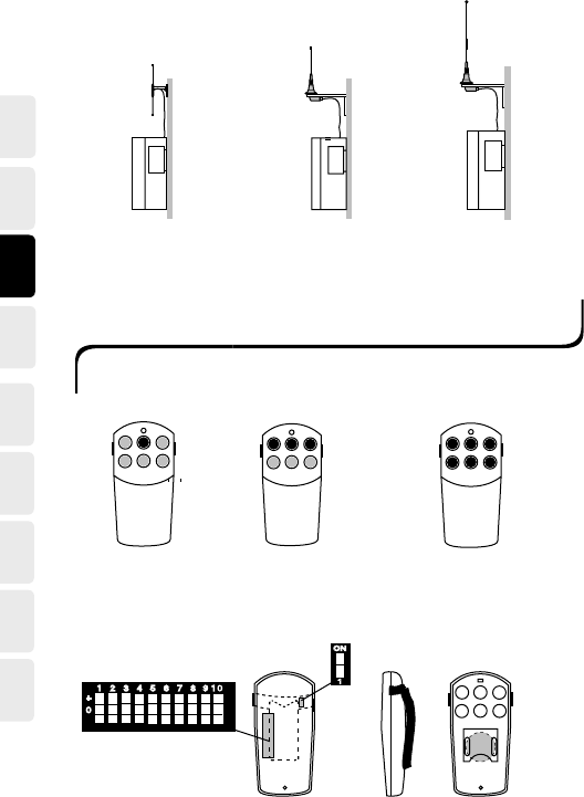
PLACEMENT OF THE AERIAL AND RECEIVER
The receiver should be placed:
-As far as is possible, protected from the elements.
-With cable holders facedown.
Placement of the receiver aerial
-Place the aerial high above the ground.
-The aerial should not be in the vicinity of metal objects such as electrical cables
and
other aerials.
DK
SE
NL
ES
FRDE
GB
US NO
SE
NLES
FR
DE
GB
US NO DK
DIP-433K3 1/4-433Kx 5/8-433Kx
X= 3, 5, or 10m aerial cable
+
0
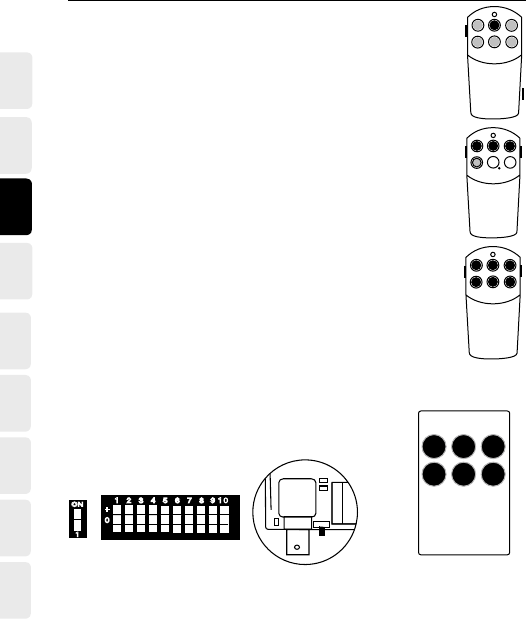
HANDHELD TRANSMITTER MINI
Dimensions:
84x40x16mm
T60TX-01SHL
with 1 button function
T60TX-03SHL
with 3 button functions
T60TX-06SHL
with 6 button functions
Battery 3V
123
456
1 2 3
+
4
123 5678
9 1 0
+
0
(B)
ON
1
(A) System switch
Code switch

DK
SE
NL
ES
FRDE
GB
US NO
SE
NLES
FR
DE
GB
US NO DK
System switch*
*Note: During adjustment, the transmitter must be turned off.
Dimensions: 98x62x22mm
(A)
(B)
System switch
Code switch
T60TX-06SOL
with 1, 3, 4, or 6 button functions Battery 9V
HANDHELD TRANSMITTER MIDI
(B)
(A)
MOBILE TRANSMITTER MAXI
Transmitter T60TX-15SML
with 15 button functions
Dimensions:
143x62x38mm
Function buttons
Battery 9V
Port no. buttons
Shortcuts for functions
T60TX-15ML
Code switch
DK
SE
NL
ES
FRDE
GB
US NO
SE
NLES
FR
DE
GB
US NO DK
SHORTCUT FOR ONE FUNCTION (T60TX-15DML)
The * and # buttons are used to program a shortcut (1 selection per but-
ton) for a specic function. To program a shortcut set the port you wish
to save, press * or # for more than 3 seconds (the display ashes). The
port has now been saved as a shortcut. To reach the shortcut, press the
appropriate button once.
Note: Shortcuts only in T60 mode and 460-93 mode.
1 2
3 4
5 6
7 8
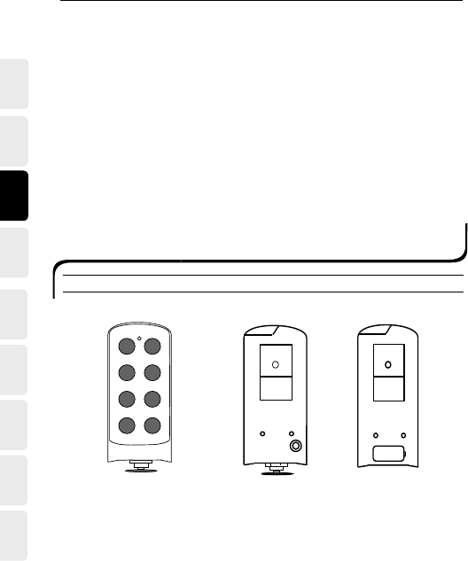
T60TX-08ERL
with 8 button functions
T60TX-0xSzL
Rear 9V
ROBUST TRANSMITTER MAXI
T60TX-0XYZL*
Dimensions: 160x70x35mm
Rear
Rechargeable battery
and stop switch

DK
SE
NL
ES
FRDE
GB
US NO
SE
NLES
FR
DE
GB
US NO DK
SUPPLY VOLTAGE
T60TX-08SRL 9V Battery
T60TX-04SDL
T60TX-0xCRL Rechargeable battery
T60TX-04CDL
T60TX-0xERL Rechargeable battery and stop switch
T60TX-04EDL
T60TX-04xDL
ON
1
4
1 2 3 5 678910
+
0
-
ON
1
T60TX-04EDL
Circuit board
ON
1
(A1) (A2)
(B)
3(7)
1(5) 2(6)
4(8)
Stop switch
4 dual function buttons
41 2 3 5 6 7 8 9 10
+
0
-
ON
1
T60TX-04XDL&T60TX-0XYRL
* x = Number of buttons
y = Transmitter type (9V, Rechargeable, Rechargeable + Stop switch)
z = Enclosure type

DK
SE
NL
ES
FRDE
GB
US NO
SE
NLES
FR
DE
GB
US NO DK
T60TX-04YDL & T60TX-0XYRL
The transmitter is equipped with 3 switches and a stop switch.
System switch (A1):
With (A1) in the ON position, the transmitter communicates with the T60
system and in position 1 (OFF) with the 460 system. When adjusting, the
transmitter must be turned off.
Mode switch (A2):
With (A2) in the ON position, continual transmission is activated (only
T60TX-0xERL & T60TX-04EDL) and in position 1 (OFF) normal transmis-
sion is activated.
In the latter case, the transmitter functions like a T60TX-0xCRL with the
stop switch acting as as a circuit breaker.
Code switches (B):
Coding the transmitter and receiver.
Stop switch:
For continual transmission, the stop switch must be pulled out and buttons
1 and 2 held down for at least 500ms.
To stop continual transmission, the stop switch must be pressed in.
DK
SE
NL
ES
FRDE
GB
US NO
SE
NLES
FR
DE
GB
US NO DK
T60RX-04XSL
Operating voltage: 12-28V AC/DC or *48/115/230V AC
Dimensions: 132x133x45mm
Enclosure: IP 65
4
RECEIVER T60RX-04XSL
123
5
6
7
8
9
10
*
1 2 3 4 5 6 7 8 9 10 11 12
Note: Connecting the recei-
ver – see Appendix D
1. Yellow LED. Lights when the receiver has the correct supply voltage.
2. Green LED. Lights when the receiver receives a radio signal.
3. Function button.
4. Select button.
5. Red LED. Each relay is tted with an LED that lights when the
relay switches.
6. Red LED.
6.1. Lights. -Code learning enabled.
6.2. Flashes. - Adjustable code learnt (1-10).
6.3. Flashes twice. - One or more xed individual codes have been learnt.
7. Yellow LED. Flashes when one of the relays has a latching function.
8. Green LED. Flashes when one of the relays is interlocked.
9. Connection terminal for the supply voltage.
10. BNC contact for the aerial.

DK
SE
NL
ES
FRDE
GB
US NO
SE
NLES
FR
DE
GB
US NO DK
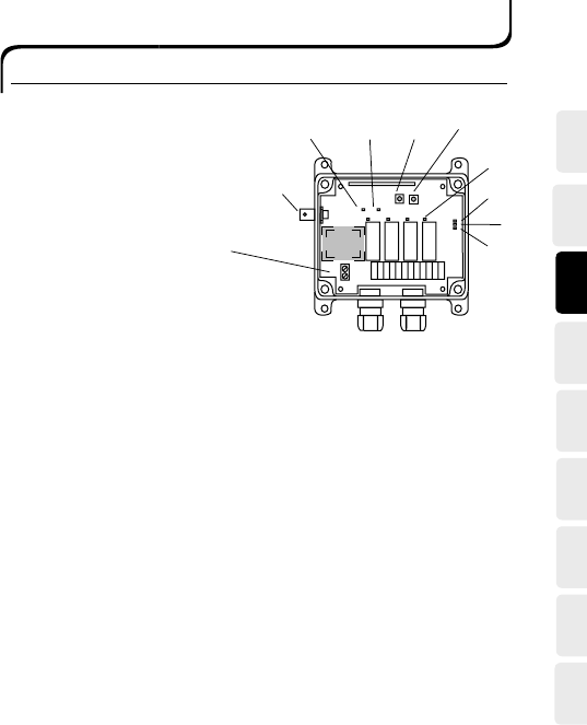
T60RX-08xxL
Operating voltage: 12-28V AC/DC or *48/115/230V AC
Dimensions: 175x125x45mm
Enclosure: IP 65
ROBUST RECEIVER T60RX-0XYSL
2
34
5
8
9
10
Note: Connecting the
receiver – see Appendix D
* TRAFO
167
1. Yellow LED. Lights when the receiver has the correct supply voltage.
2. Green LED. Lights when the receiver receives a radio signal.
3. Function button.
4. Select button.
5. Red LED. Each relay is tted with an LED that lights when the
relay switches.
6. Red LED.
6.1. Lights. - Code learning enabled.
6.2. Flashes. - Adjustable code learnt (1-10).
6.3. Flashes twice. - One or more xed individual codes have been learnt.
7. Yellow LED. Flashes when one of the relays has a latching function.
8. Green LED. Flashes when one of the relays is interlocked.
9. Connection terminal for the supply voltage.
10. BNC contact for aerial.

DK
SE
NL
ES
FRDE
GB
US NO
SE
NLES
FR
DE
GB
US NO DK
PROGRAMMING RECEIVER T60RX-0XYZL*
SELF-INSTRUCTION OF ADJUSTABLE CODE
1. Press the function button for at least 0.3 seconds, max. 4 seconds.
-Red LED no. 6 lights (programming the code).
Pressing the function button repeatedly allows you to select between code
learning (red LED), latching relay function (yellow LED), or interlocking
(green LED).
2. Now press the select button.
-All red LEDs light above the relays.
3. Now press the function button and select which relay(s) is(are) to be
coded.
Note: Pressing the function button repeatedly allows you to select which one of the
relays is to be coded. You can choose between all relays or only 1, 2, or up to 8.
A red LED lights above the relays that can be coded. If all the relays are chosen,
the rst relay will work with function button 1 on the transmitter, the second
relay with function button 2 on the transmitter, and so on.
4. Press the select button again for at least 0.3 seconds, max. 4 seconds.
-Release the select button.
5. Then press the function button on the transmitter (that is to control the
relay) until red LED no. 6 blinks 3 times.
6. The transmitter’s adjustable code is now stored.
-Red LED no. 6 ashes and indicates that the transmitter is programmed.
* Does not apply to T60RX-03ADL, T60RX-01 APL, or T60RX-01ARL.

DK
SE
NL
ES
FRDE
GB
US NO
SE
NLES
FR
DE
GB
US NO DK
ERASE ALL RELAYS OR INDIVIDUAL RELAYS
1. Press the function button for at least 0.3 seconds, max. 4 seconds.
-Red LED no. 6 lights.
2. Now press the select button.
-All red LEDs light above the relays.
3. Release the select button.
4. Now press the function button and select the relay to be erased.
Note: Pressing the function button repeatedly allows you to select which relay(s)
is(are) to be erased. You can choose between all relays or only 1, 2, or up to 8.
A red LED lights behind the relay that can be erased.
5. Press the select button again for at least 6 seconds.
-The red LEDs above the relays go out.
REGISTER ADJUSTABLE AND FIXED INDIVIDUAL CODES ON ALL
OR INDIVIDUAL RELAYS
1. Press the function button for at least 0.3 seconds, max. 4 seconds.
-Red LED no. 6 lights (learning code).
Pressing the function button repeatedly allows you to select between adjustable code (red LED),
latching (yellow LED), and interlocking (green LED).
2. Now press the select button.
-All red LEDs light above the relays.
3. Now press the function button and select which relay(s) is(are) to be coded.
Note: Pressing the function button repeatedly allows you to select which relays are to be
coded. You can choose between all relays or only 1, 2, or up to 8. A red LED lights above
the relay that can be coded. If all of the relays are chosen the rst relay will work with
function button 1 on the transmitter, the second relay with function button 2 on the
transmitter, and so on.
4. Press the select button for at least 0.3 seconds, max. 4 seconds.
5. Release the select button, wait max. 1 second.
6. Press the select button again for more than 1 second.
7. Now press the function button on the transmitter that is to control the relay.
8. The transmitter’s adjustable code and xed individual code are now stored.
-Red LED no. 6 double-ashes to indicate that the private code has been
stored.

DK
SE
NL
ES
FRDE
GB
US NO
SE
NLES
FR
DE
GB
US NO DK
PROGRAMMING THE LATCHING/INSTANTANEOUS FUNC-
TION
1. Press the function button twice so that green LED no. 7 lights
(programming the latching relay).
2. Now press the select button.
-The red LED above the rst relay lights.
3. Press the select button and select whether the rst relay should be
latching or not. If the yellow LED is on then the relay is latching, if it is
off the relay is instantaneous.
Note: Using the function button you can step through whether it is relay 2, 3, or 8 that
is to have a latching function. After the nal relay the program is stored
4. Continue to press the function button until all relay LEDs go out.
-Yellow LED no. 7 ashes once (the function is now stored).
5. The latching function has now been programmed.
-Yellow LED no. 7 ashes and indicates that one of the relays
has a latching function..
PROGRAM/ERASE THE INTERLOCK FUNCTION
1. Press the function button 3 times so that green LED 8 lights
(programming the interlock).
2. Now press the select button.
-The red LEDs above relays 1 and 2 light.
Note: Press the function button once to program interlocking over relays 3 and 4, and
so on.
3. Continue to press the function button until all relay LEDs go out.
-Green LED no. 8 ashes once (the function is now stored).
4. The interlock is now programmed.
-Green LED no. 8 ashes and indicates that the interlock is pro-
grammed.
DK
SE
NL
ES
FRDE
GB
US NO
SE
NLES
FR
DE
GB
US NO DK
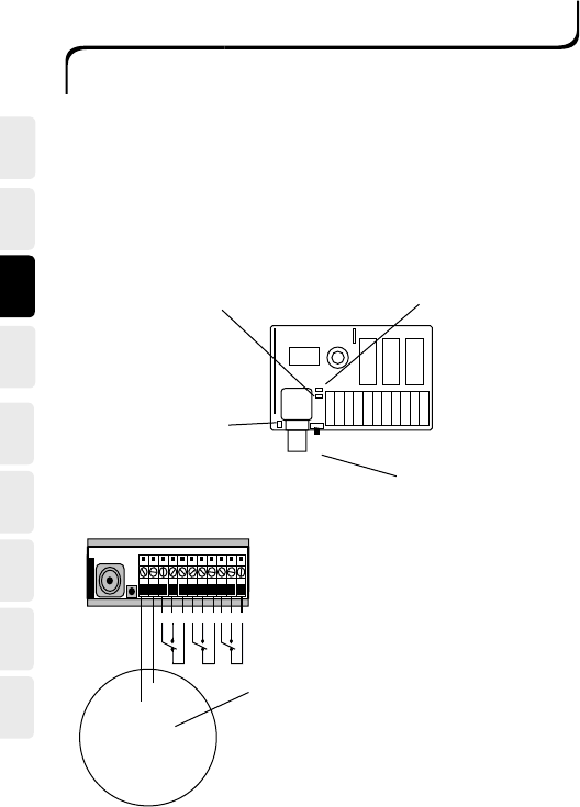
DIN-RECEIVER T60RX-03ADL
Frequency: 433.92MHz
Operating voltage: 12-24V AC/DC
Dimensions: 86x30x58mm
Enclosure: IP 20, for internal installation
12/24V AC/DC
12/24V AC/DC
C NO NC C NO NC C NO NC
Green LED indicates
signal reception.
Button for self-instruction/
erasing.
Red LED indicates programming
status.
Yellow LED indicates supply
voltage.
Power connection.

DK
SE
NL
ES
FRDE
GB
US NO
SE
NLES
FR
DE
GB
US NO DK
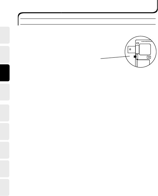
PLUG-IN RECEIVER T60RX-01APL
Frequency: 433.92MHz
Operating voltage: 12-24V AC/DC
Dimensions: 70x58x40mm
Enclosure: IP 23, for internal installation
5
6
11
10
Green LED indicates signal
reception. Button for self-instruction/
erasing.
Red LED indicates
programming status.
Yellow LED indicates supply
voltage.
BNC connector.
Side 1
Side 2
Power connection
11-pin connector
5. 12-24V AC/DC
6. 12-24V AC/DC
11. NC
10. NO
DK
SE
NL
ES
FRDE
GB
US NO
SE
NLES
FR
DE
GB
US NO DK
Register fixed individual code:
1. Press the self-instruction button for at least 0.3 seconds, max. 4 seconds.
2. Release the button (less than 1 second).
3. Press the button again (longer than 1 second).
-Private program mode, red LED goes out and lights again.
4. Press the desired function button.
-Red LED ashes rapidly three times.
5. The private code is now stored.
-Red LED double-ashes every other second.
PROGRAMMING RECEIVER T60RX-03ADL,
T60RX-01APL, AND T60RX-01ARL
SELF-INSTRUCTION FOR ADJUSTABLE AND FIXED CODES
Register adjustable code:
1. Press the self-instruction button for at least 0.3 seconds, max. 4 sec-
onds.
2. Release the button.
-Programming mode, red LED lights.
3. Press the desired function button.
-Red LED ashes rapidly three times.
4. The adjustable code is now stored.
-Red LED ashes. Once every other second.

DK
SE
NL
ES
FRDE
GB
US NO
SE
NLES
FR
DE
GB
US NO DK
CO-PROGRAMMING THE TRANSMITTER AND DIN-RECEI-
VER
T60TX-15SML AND T60RX-03ADL
1. Check that the transmitter’s system switch (A) is in the ON position.
2. Set a unique code on the transmitter’s code switch (B) 1-10.
3. If buttons 1-3 are pressed, the relays in the receiver will function as
buttons 1-3. If buttons 4-6 are pressed, the relays in the receiver will
function as buttons 4-6, and so on.
-Red LED lights (programming mode 6 seconds).
4. Press the desired function button (1-15) on the transmitter.
-Red LED ashes three times.
5. Check that the relay switches when the same function but-
ton is pressed again.
(A) (B)
(C)
ON
1
4
123
5678
9 1 0
+
0
T60TX-15DML AND T60RX-03ADL
1. Check that the transmitter’s system switch (A) is in the ON
position.
2. Set a unique code on the transmitter’s code switch (B) 1-10.
3. Press the self-instruction button (C) on the receiver.
-Red LED lights (programming mode 6 seconds).
4. Press the desired port number button (0-999) and an op-
tional function button (up, stop, down) on the transmitter.
-Red LED ashes three times.
5. Check that the relay switches when one of the transmitter buttons is
pressed again.
DK
SE
NL
ES
FRDE
GB
US NO
SE
NLES
FR
DE
GB
US NO DK
T60TX-0XSHL/T60TX0XSOL AND T60RX-03ADL
1. Check that the transmitter’s system switch (A) is in the ON
position.
2. Set a unique code on the transmitter’s code switch (B) 1-10.
3. Press the self-instruction button (C) on the receiver.
-Red LED lights (programming mode 6 seconds).
Note: Only receiver T60RX-03ADL.
4. If buttons 1-3 are pressed, the relays in the receiver will func-
tion as buttons 1-3. If buttons 4-6 are pressed, the relays in
the receiver will function as buttons 4-6, and so on.
-Red LED lights (programming mode 6 seconds).
5. Press the desired function button (1-6) on the transmitter.
-Red LED ashes three times.
6. Check that the relay switches when the same function button
is pressed again.
41 2 3 5 6 7 8 9 1
0
(A) (B)
ON
1
(C)
4
123
56789 1
0
+
0
1
23
456
31 2

DK
SE
NL
ES
FRDE
GB
US NO
SE
NLES
FR
DE
GB
US NO DK
SUPPLEMENT FOR THE 460 SYSTEM
T60TX-15DML*
Type 401RVL9 and 403RVL9 transmitters with knob 1-10:
1. Check that the transmitter’s system switch (A) is in position 1 (OFF).
2. Check that code switch (B) 9 is in the 0 (zero) position.
3. Set code switch 10 to either the minus or plus position depending on
whether you are using A or B coding on the old transmitter (robust
transmitter).
4. Set a code on the transmitter’s 4 rst switches (code switches 1-4)
identical to the receiver’s (code switches 5-8 not used).
5. Check that the relay switches when one of the transmitter buttons is
pressed. The numbers on the transmitter display correspond to the
knob. Press a number followed by the transmit button and verify that
the corresponding relay switches.
See code table 1-10, Appendix A.
* Transmitter T60TX-15DML in the T60 system is compatible with trans-
mitter Type 401RVL9 and 403RVL9 in the 460 system.
(A) (B)
4
123
5678
9 1
0
+
0
ON
1

DK
SE
NL
ES
FRDE
GB
US NO
SE
NLES
FR
DE
GB
US NO DK
Type 401RVL9 and 403RVL9 with knob 0-15:
1. Check that the transmitter’s system switch (A) is in position 1 (OFF).
2. Check that code switch (B) 9 is in the - (minus) position.
3. Set code switch 10 to either the minus or plus position depending on
whether you are using A or B coding on the old transmitter (robust
transmitter).
4. Set a code on the transmitter’s 4 rst switches (code switches 1-4)
identical to the receiver’s (code switches 5-8 not used).
5. Check that the relay switches when one of the transmitter buttons is
pressed.
See code table 0-15, Appendix B.
Type 460-93 transmitter:
1. Check that the transmitter’s system switch (A) is in position 1 (OFF).
2. Check that code switch (B) 9 is in the + (plus) position.
3. Set codes on the transmitter’s 3 rst switches (code switches 1-3)
identical to the receiver’s codes (code switches 4-8 not used).
4. Check that the relay switches when one of the transmitter buttons is
pressed.
See code table 460-93, Appendix C.
Note:
When you select the port on the T60TX-15DML transmitter, a combina-
tion of the rst digit and the last two digits is entered when used together
with a 460-93 transmitter.
Example: In order to control port A2 in accordance with table A, enter
the combination 102; to control port D3 in accordance with table D, enter
the combination 403; and so on.

DK
SE
NL
ES
FRDE
GB
US NO
SE
NLES
FR
DE
GB
US NO DK
T60TX-0XSHL/T60TX-0XSOL/T60TX-15SML
Type 401L-406L transmitter:
1. Check that the transmitter’s system switch (A) is in position 1 (OFF).
2. Set codes on the transmitter’s code switches (B) 1-8 identical to the
existing receiver (9-10 not used).
3. Check that the relay switches when the same function button is
pressed again.
-
(A)
123
456
1 2 3
ON
1
(B)
4
123
5678
9 1
0
+
0
ROBUST TRANSMITTER T60TX-04YDL & T60TX-0XYRL
Type 408RFLI9, 408RFLIC, 408RFLIE, 404RFLI9 transmitter:
Programming the 460 and T60 systems for normal or continuous transmis-
sion.
1. Check that the transmitter’s system switch (A1) is in position 1 (OFF)
for the 460 system or in the ON position for the T60 system.
2. Check that the transmitter’s mode switch (A2) is in position 1 (OFF)
for normal transmission or in the ON position for continuous trans-
mission.
3. Set codes on the transmitter’s code switches (B) 1-8 identical to the
receiver for the 460 system. For the T60 system, set codes on the
transmitter’s code switches 1-10.
4. Check that the relay switches when the same function button is pressed
again. (B)
ON
1
(A1) (A2)
41 2 3 5 6 7 8 9 10
+
0
-
ON
1

DK
SE
NL
ES
FRDE
GB
US NO
SE
NLES
FR
DE
GB
US NO DK
SERVICE AND SUPPORT
For service, returns, and complaints, please write an R/A number on each
consignment sent to Tele Radio AB.
(Contact Tele Radio AB to obtain an R/A number). Products that have an
R/A number are given priority over those that do not have one.
Service
If the product stops working during the warranty period, Tele Radio AB of-
fers full servicing of the product. The product should be sent to Tele Radio
AB (to the specied address).
Note: The warranty does not apply to faults that arise due to product
modications or incorrect installation.
Support
This service is designed so that you receive the results you need in a fast
and professional manner.
When you contact Tele Radio’s Support you should have the following
noted:
System, model, and a description of the problem.
DK
SE
NL
ES
FRDE
GB
US NO
SE
NLES
FR
DE
GB
US NO DK
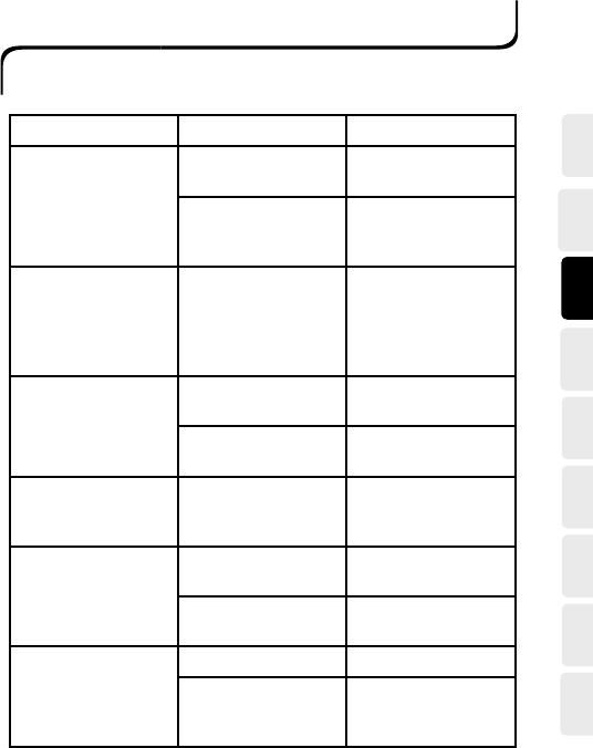
FAULTY FUNCTION POSSIBLE CAUSES REMEDY
The receiver does
not work when you
transmit.
The receiver is incor-
rectly connected.
Inspect receiver con-
nections.
Incorrect operat-
ing voltage to the
receiver.
Check the supply
voltage.
The receiver’s green
LED lights when you
transmit, but the re-
lays are not activated.
The codes in the
transmitter and
receiver do not cor-
respond, i.e., they are
not identical.
Check the coding.
The receiver’sgreen
LED does not light
when you transmit.
The battery is dis-
charged.
Replace the battery.
The transmitter is
damaged.
Contact your dealer
.
The receiver’s green
LED lights when you
are not transmitting.
Another unit is trans-
mitting in the vicinity
on a similar frequency.
Contact your dealer
.
The transmitter’s LED
does not light when
you transmit.
The battery is dis-
charged.
Replace or charge the
battery.
The transmitter is
damaged.
Contact Tele Radio’s
support.
The range istoo short. Bad battery. Replace the battery.
Aerial cables are dam-
aged or incorrectly
installed.
Check the aerial
connection.
TROUBLE SHOOTING CHART
If the equipment is not working as it should, we would ask you to follow
the steps below.
If you have followed these instructions and still cannot get the radio system to work properly,
please contact your dealer.

DK
SE
NL
ES
FRDE
GB
US NO
SE
NLES
FR
DE
GB
US NO DK

DK
SE
NL
ES
FRDE
GB
US NO
SE
NLES
FR
DE
GB
US NO DK
THIS DEVICE COMPLIES WITH PART 15 OF THE FCC RULES. OPERATION
IS SUBJECT TO THE FOLLOWING TWO CONDITIONS: (1) THIS DEVICE MAY
NOT CAUSE HARMFUL INTERFERENCE, AND (2) THIS DEVICE MUST
ACCEPT ANY INTERFERENCE RECEIVED, INCLUDING INTERFERENCE THAT
MAY CAUSE UNDESIRED OPERATION.
NOTE: THE MANUFACTURER IS NOT RESPONSIBLE FOR ANY RADIO OR
TV INTERFERENCE CAUSED BY UNAUTHORIZED MODIFICATIONS TO THIS
EQUIPMENT. SUCH MODIFICATIONS COULD VOID THE USER'S AUTHORITY
TO OPERATE THE EQUIPMENT.