Tele Radio C1202A TRANSMITTER User Manual IM PN CE002 A01 EN

Tele Radio AB TRANSMITTER IM PN CE002 A01 EN

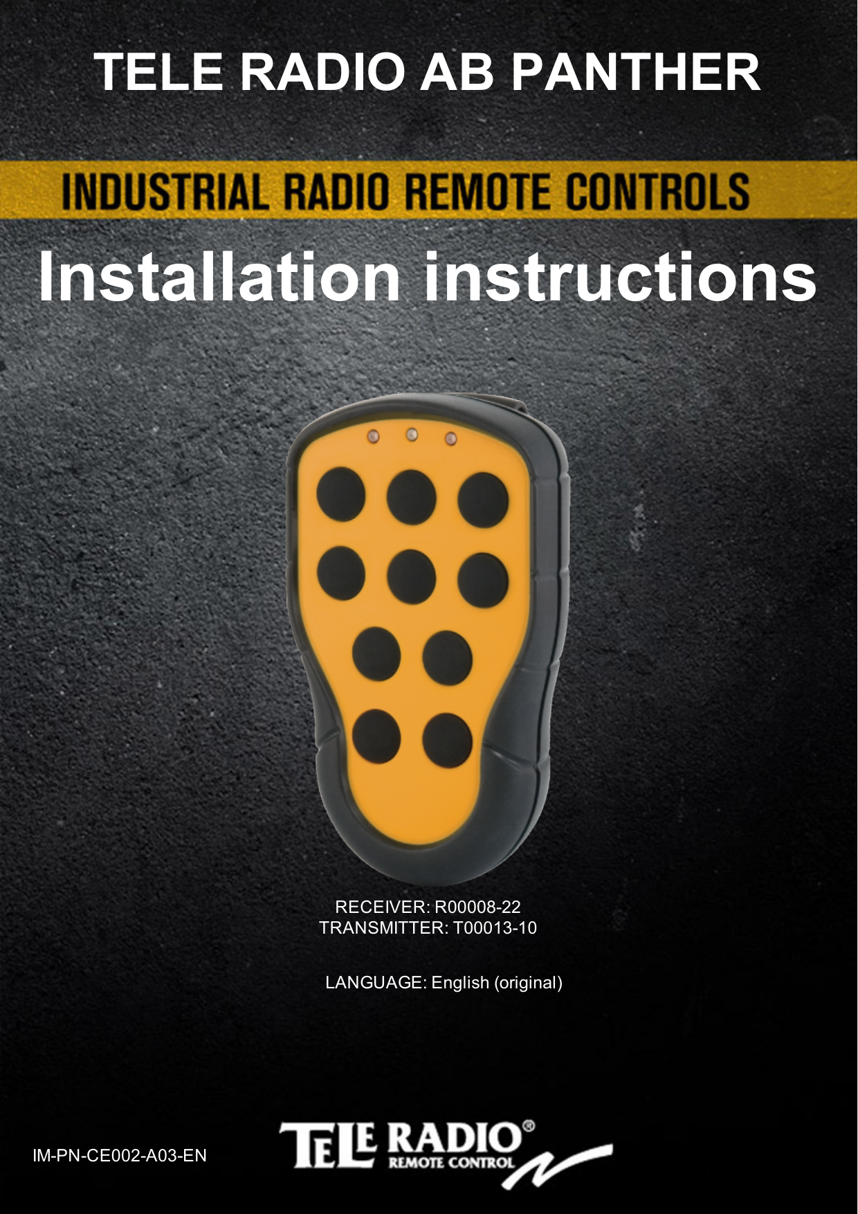
ONFC1202A & 4807A-C1202A User Manual Rev1

RECEIVER: R00008-22TRANSMITTER: T00013-10LANGUAGE: English (original)IM-PN-CE002-A03-ENInstallation instructionsTELE RADIO AB PANTHER
-2-CHAPTER 1: CUSTOMER INFORMATIONThank you for purchasing a Tele Radio AB   productREADALLINSTRUCTIONS ANDWARNINGS CAREFULLY BEFOREMOUNTING, INSTALLING ANDCONFIGURATING THEPRODUCTS. These instructions are published by Tele Radio AB without any guarantee. The instructions may be removed or revised by Tele Radio AB at any time and without further notice. Corrections and additions will be added to the latest version of the instruction. IMPORTANT! These instructions contain a separate chapter directed towards end users. The chapter can be printed and handed to end users. The instructions that contain information on the installation and configuration of the radio remote control unit on the machine are not intended to be passed on to the end user. Only such information may be passed on to the end user that is needed to operate the machine correctly by radio remote control. Tele Radio AB products are covered by a guarantee/ warranty against material, construction or manufacturing faults. During the guarantee/ warranty period, Tele Radio AB may replace the product or faulty parts with new. Work under guarantee/ warranty must be carried out by Tele Radio AB or by an authorized service center specified by Tele Radio AB. Contact your Tele Radio AB representative if you need support or service. ©Tele Radio AB, 2012Datavägen 21SE-436 36 ASKIMSWEDENTel: +46-31-748 54 60Fax: +46-31-68 54 64www.tele-radio.com
-3-Warnings & restrictionsIMPORTANT! Tele Radio remote controls are often built into wider applications. We recommend that the system is provided with a wired emergency stop where necessary.NOTE! We recommend that the functionality of the STOP button is being tested at a regular basis: At a minimum, when used for 200 hours. Test the STOP button by pressing it and pulling it out. INSTALLING, CONNECTING AND MOUNTINGn  Allow only licensed or qualified personnel to install the product. n  Switch the power supply off to the receiver before connecting the equipment.n  Check that you have connected the power supply to the correct connection terminal. n  To utilize the safety of the system, use the stop relays in the safety circuitry of the object that you want to con-trol. n  Use undamaged cables. No cables should hang loose. n  Avoid installing in areas affected by strong vibrations. n  Place the receiver well away from wind, damp and water. n  Cable glands and vent plugs must face down to prevent water from seeping in.THE USERn  Make sure that the user is following the instructions.n  Make sure that the user has reached the certified age of   your country to operate the equipment.n  Make sure that the user is not under the influence of   drugs, alcohol and medicines.n  Allow only qualified personnel to have access to the    transmitter and operate the equipment.n  Make sure that the user does not leave the transmitter   unsupervised.n  Make sure that the user always turns the transmitter off   when not in use.n  Make sure that the user keeps a good overview of the   work area.MAINTENANCEn  Use the stop button to start and turn off the transmitter   as often as possible.n  When error messages are shown, it is very     important to find out what caused them.n  If the stop button is mechanically damaged, contact your   representative for service immediately.n  Always contact your representative for service and maintenance work on the product.n  Write down the serial numbers of the receivers and    transmitters used. This information should be recorded   on the “Settings document” for your product (download   from our website).n  Avoid registering transmitters to receivers where it is   not being used.n  Keep the safety instruction for future reference.  Always   download the configurations instruction from our web  site for the latest version available.
Chapter 2: SYSTEM INFORMATIONCHAPTER 2: SYSTEM INFORMATIONApplication area for the Panther systemThe Tele Radio AB Panther remote control systems are aimed for remote controlling of industrial equipment where a high flexibility is required. -4-
-5-CHAPTER 3: PRODUCT PAGESWARNING! The receiver must NOT be opened by any other than a qualified installer. Make sure to turn the electricity off before opening the receiver.R00008-22 BASE BOARD RECEIVER1. Function LEDs (1= red, 2= yellow, 3= green, 4= orange) 6. Power LED (yellow) 2. Function button (Cancel) 7. Terminal block for motor 1                    3. Function relay LED (red) 8. Terminal block for motor 24. Programming connector 9. Terminal block for relay 5. Terminal block for digital inputs 10. Function relay
-6-ANALOGUE EXPANSION BOARD11. Terminal block for analogue inputs/ outputs 12. Indication LED for communication with the base board (green)
-7-COMPONENTS DESCRIPTIONTERMINAL BLOCK FOR DIGITAL INPUTS40 GND 41 Digital input 142 Digital input 243 Digital input 344 Digital input 445 Digital input 546 Digital input 647 Digital input 748 Digital input 849 GND TERMINAL BLOCK FOR MOTOR 11 Input power GND2 Motor output M1A3 Motor output M1B4 Input power 12-24 V DC
-8-TERMINAL BLOCK FOR MOTOR 25 Input power GND6 Motor output M2A 7 Motor output M2B8 Input power 12-24 V DCTERMINAL BLOCK FOR ANALOGUE INPUTS/ OUTPUTS21 Analogue input 122 Analogue input 223 +3.3 V DC 24 Analogue output 125 GND 26 +12 V DC 27 GND 28 Analogue output 229 +5 V DC 
-9-TECHNICAL DATA Number of function relays 1 (potential free*, 8A)Digital inputs 8Number of DC motor controls 2Number of analogue outputs 2Number of analogue inputs 2Duplex communication NoMin./max. current consumtion  12 V DC: Min.** 0.5mA/ Max.*** 20A24 V DC: Min.** 0.5mA/ Max.*** 20 AOperating frequency 2405-2480 MHzNumber of radio channels 16 (channel 11-26)Channel separation 5 MHzIP class 66Size 121 x 117 x 51 mm./ 4.75 x 4.6 x  2 in.Weight 420 g./ 0.926 lbs.Antenna 1 internal* potential free means that you have to supply voltage to get voltage out of a relay (e.g. via the included connection comb) ** Minimum current consumption= Receiver on, no radio communication established, sleep mode activated. *** Maximum current consumption= Maximum output (10A) on motor 1 output and maximum output (10A) on motor 2 output. RECEIVER FUNCTIONALITYPRESS BUTTON:  RESULTSIN:1The PWM output between M1A and M1B will be positive and increase to the same voltage level as the input between (+) and (-).2The PWM output between M2A and M2B will be positive and increase to the same voltage level as the input between (+) and (-).3The relay will be active, and the PWM output between M2A and M2B will be positive and increase to the same voltage level as the input between (+) and (-).4The PWM output between M1A and M1B will be negative and increase to the same voltage level as the input between (+) and (-).5The  PWM output between M2A and M2B will be negative and increase to the same voltage level as the input between (+) and (-).6The relay will be active, and the PWM output between M2A and M2B will be negative and increase to the same voltage level as the input between (+) and (-). 
-10 -MEASUREMENTS FOR MOUNTING OF THE RECEIVER
-11 -TRANSMITTER T00013-101. LED 1                     3. LED 22. Top LED 4. 1-step push buttons 1-10TRANSMITTER MEASUREMENTS
-12 -TECHNICAL DATANo. of buttons 10 x 1-step buttonsOn/off switch YesSize 114.5 x 66 x 37.5 mm./ 4.5 x 2.6 x 1.48 in. Weight 135 g./ 0.3 lbs. (excluding batteries)Number of channels 16 (channel 11-26)Operating frequency 2405-2480 MHz. Radio type Low IF topologyON/OFF SWITCHThe  transmitter has an on/off switch on the backside. The on/off switch has 2 positions: 1= on0= offThe on/off switch breaks the power supply from the battery. When in position 0/off, the transmitter can not be started.
FCC/ IC LABEL The FCC IC label is placed in the back of the transmitter. See picture. FCC statementStatement for warning:Caution: The user is cautioned that changes or modifications not expressly approved by the party responsible for compliance could void the user's authority to operate the equipment.This device complies with Industry Canada licence-exempt RSS standard(s) and Part 15 of the FCC Rules. Operation is subject to the following two conditions:(1) this device may not cause harmful interference, and(2) this device must accept any interference received, including interference that may cause undesired operation.Le présent appareil est conforme aux CNR d'Industrie Canada applicables aux appareils radio exempts de licence et la partie 15 des Règles FCC. L'exploitation est autorisée aux deux conditions suivantes :(1) l'appareil ne doit pas produire de brouillage, et(2) l'utilisateur de l'appareil doit accepter tout brouillage radioélectrique subi, même si le brouillage est susceptible d'en compromettre le fonctionnement.This equipment complies with FCC and IC radiation exposure limits set forth for an uncontrolled environment. End user must follow the specific operating instructions for satisfying RF exposure compliance. This transmitter must not be co-located or operating in conjunction with any other antenna or transmitter.Cet appareil est conforme aux limites d’exposition au rayonnement RF stipulées par la FCC et l’IC pour une utilisation dans un environnement non contrôlé. L'utilisateur final doit suivre les instructions de fonctionnement spécifiques pour le respect d'exposition aux RF. Lesémetteurs ne doivent pas être placées près d’autres antennes ou émetteurs ou fonctionner avec ceux-ci.Note: this equipment has been tested and found to comply with the limits for a class b digital device, pursuant to part 15 of the FCC rules. These limits are designed to provide reasonable protection against harmful interference in a residential installation. This equipment generates, uses and can radiate radio frequency energy and, if not installed and used in accordance with the instructions, may cause harmful interference to radio communications. However, there is no guarantee that interference will not occur in a particular installation. If this equipment does cause harmful interference to radio or television reception, which can be determined by turning the equipment off and on, the user is encouraged to try to correct the interference by one or more of the following measures:—reorient or relocate the receiving antenna.—increase the separation between the equipment and receiver.—connect the equipment into an outlet on a circuit different from that to which the receiver is connected.—consult the dealer or an experienced radio/TV technician for help.-13 -
-14 -CHAPTER 4: INSTALLERS GUIDESTART THE TRANSMITTER1. Press button 9 (the on button) for at least 1 second. 2. Release button 9  (the on button) when the top LED turns green. 3. The transmitter is started.TURN THE TRANSMITTER OFF1. Press button 10 (the off button). 2. The transmitter sends a stop command for 1 second.3. The transmitter turns off. REGISTER THE TRANSMITTER IN THE RECEIVER IMPORTANT! Do not perform this when the receiver is in a session with another transmitter. The radio communication may become disturbed or broken. 1. Press the receiver Function button  (LED 1 lights red). 2. Press button 1+ 2 on the transmitter that you want to register. 3. Receiver LED 1 flashes 3 times when the transmitter is registered. 4. If the receiver can not find the transmitter within 10 seconds, the receiver exits registration mode and goes back to normal operation. ERASE A TRANSMITTER FROM THE RECEIVER1. Press the receiver Function button (LED 1 lights red).2. Keep pressed until LED 1 goes out (approx. 4 seconds).3. Release the receiver Function button.     4. All registered transmitters are erased.
Chapter 5: BATTERY GUIDECHAPTER 5: BATTERY GUIDE BATTERY INFORMATIONWARNING! Do not recharge the batteries. Attempts to recharge may cause rupture or the leaking of hazardous liquids, which will corrode the equipment. IMPORTANT! Electronics and batteries must be physically separated before disposal. Make sure that electronics or batteries are not thrown in the household waste. Battery type 2 x 1.5V AAA alkaline batteriesSWITCH BATTERIES1.     2.      3.  1.Take off the transmitter backside by unscrewing the 5 screws (a-e).2. Switch the 2 1.5V AAA batteries. Use alkaline for optimal performance. 3. Put the transmitter backside on again using the screwdriver. -15 -
Chapter 5: BATTERY GUIDEBATTERY PRECAUTIONSObserve the following general battery warnings:n  As batteries contains flammable substances such as lithium or other organic solvents, they may cause heating, rupture or ignition.n  Risk of explosion if battery is replaced with a battery of an incorrect type.n  Do not short circuit, disassemble, deform or heat batteries.n  Never try to charge a visibly damaged or frozen battery.n  Keep batteries out of reach of small children. Should a child swallow a battery, consult a phy-sician immediately.n  Avoid direct soldering to batteries.n  When discarding batteries, insulate the + and -  terminals of batteries with insulating/ masking tape. Do not put multiple batteries in the same plastic bag.n  When improperly disposed,  lithium batteries may short circuit, causing them to become hot, burst or ignite.n  Store in a cool location. Keep batteries away from direct sunlight, high temperature, and high humidity.n  Do not throw batteries into fire.ROHS AND WEEEIn accordance with Directive 2002/95/EC on restriction of the use of certain hazardous substances in electrical and electronic equipment (RoHS) and Directive 2002/96/EC on waste electrical and electronic equipment (WEEE), Tele Radio AB strives to minimize the use of hazardous materials, promotes reuse and recycling, and reduces emissions to air, soil and water. When a commercially viable alternative is available, Tele Radio AB strives to restrict or eliminate substances and materials that pose an environmental, health or safety risk.GUARANTEE, SERVICE, REPAIRS AND MAINTENANCEThe Tele Radio AB products are covered by a guarantee/warranty against material, construction and manufacturing faults. During the guarantee/warranty period, Tele Radio AB may replace the product or faulty parts. Work under guarantee/warranty must be carried out by Tele Radio AB or by an authorized service centre specified by Tele Radio AB. This is not covered by the guarantee/ warranty: n  Faults resulting from normal wear and tearn  Parts of a consumable naturen  Products that have been subject to unauthorized modificationsn  Faults resulting from incorrect installation and use n  Damp and water damageMaintenance:n  Repairs and maintenance must be carried out by qualified personneln  Use spare parts from Tele Radio AB onlyn  Contact your representative if you require service or other assistancen  Keep the product in a dry, clean placen  Keep contacts and antennas cleann  Wipe off dust using a slightly damp, clean clothIMPORTANT! Never use cleaning solutions or high-pressure water.-16 -
Chapter 5: BATTERY GUIDECE MARKINGThis product complies with current European directives and standards. -17 -


Navigation menu