Telcosat RBB850 Repeater User Manual with correction
Telcosat Inc Repeater with correction
UserManual.wiki
>
Telcosat
>
RBB850 User Manual
>
User Manual with correction
Contents
1.
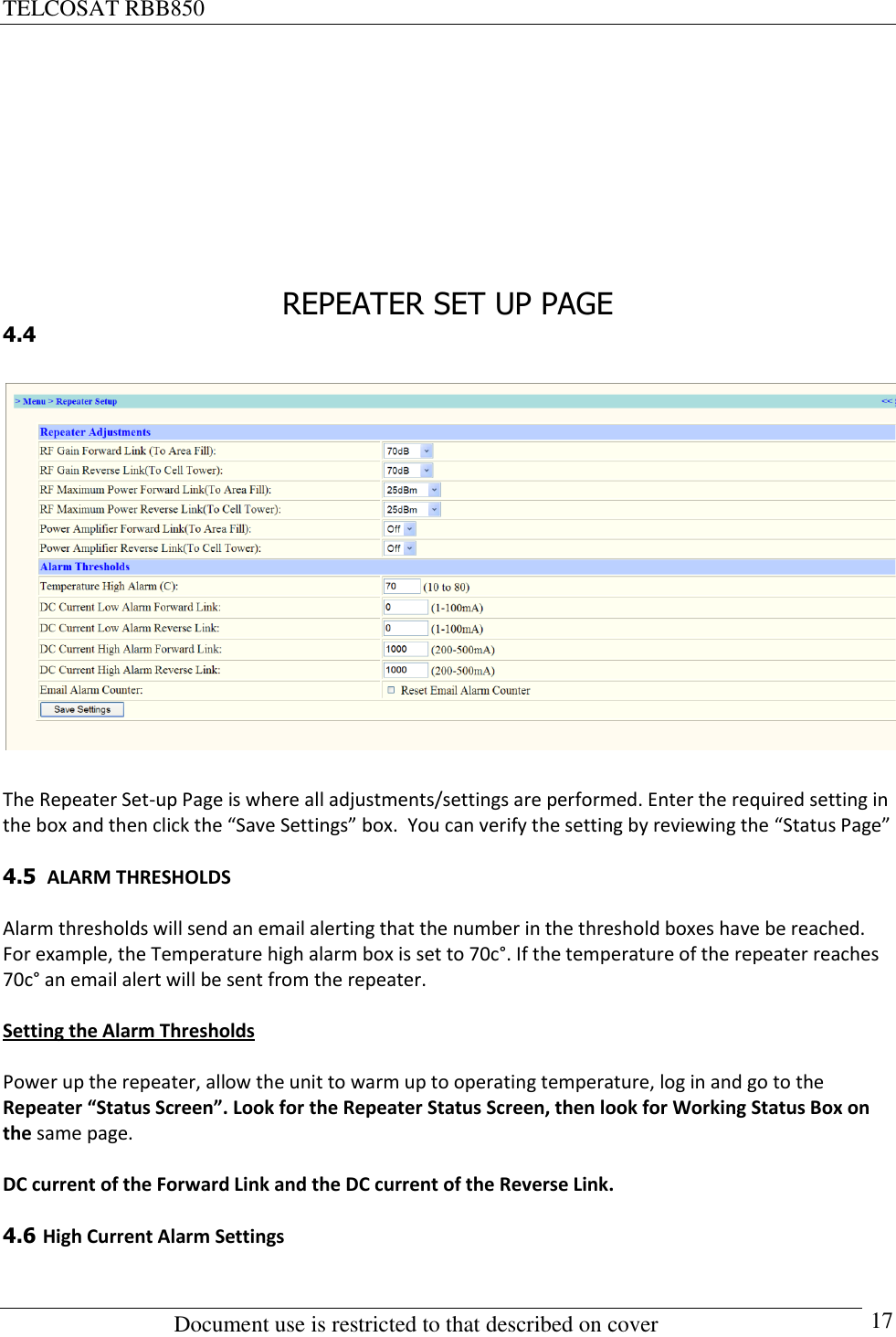
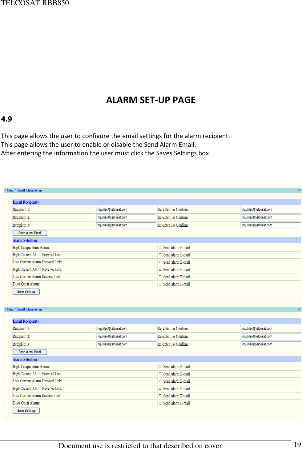
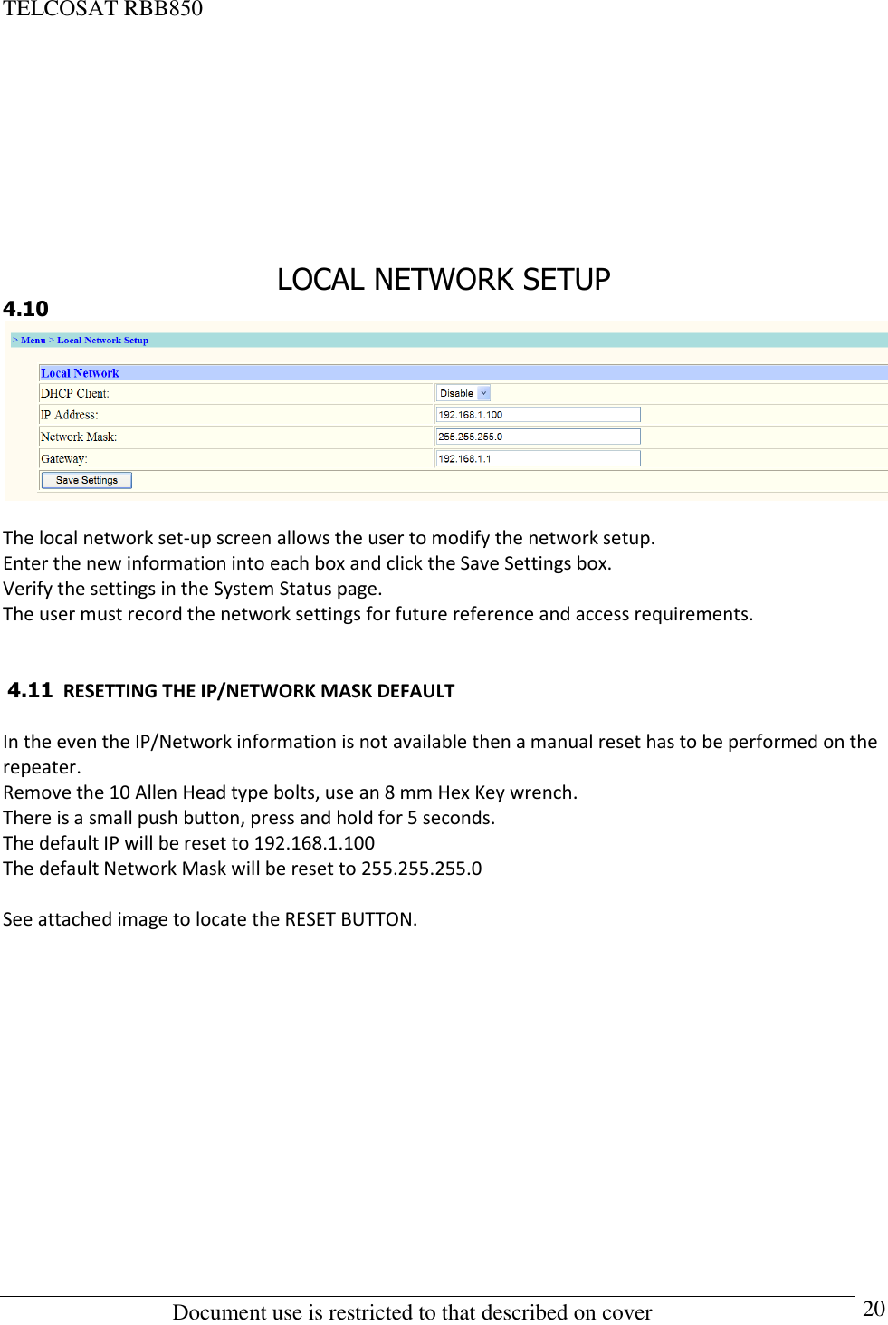
User Manual
2.
User Manual with correction
User Manual with correction
Navigation menu
Upload a User Manual
Namespaces
Wiki Guide
HTML
PDF
Info
Views
User Manual
Discussion / Help
Navigation