Technicolor Delivery Technologies Belgium TG590 Broadband Home Router User Manual Setup and User Guide
Technicolor Delivery Technologies Belgium Broadband Home Router Setup and User Guide
UserManual.wiki
>
Technicolor Delivery Technologies Belgium
>
TG590 User Manual
>
User Manual 1
Contents
1.
User Manual 1
2.
User Manual 2
User Manual 1
Navigation menu
Upload a User Manual
Namespaces
Wiki Guide
HTML
PDF
Info
Views
User Manual
Discussion / Help
Navigation
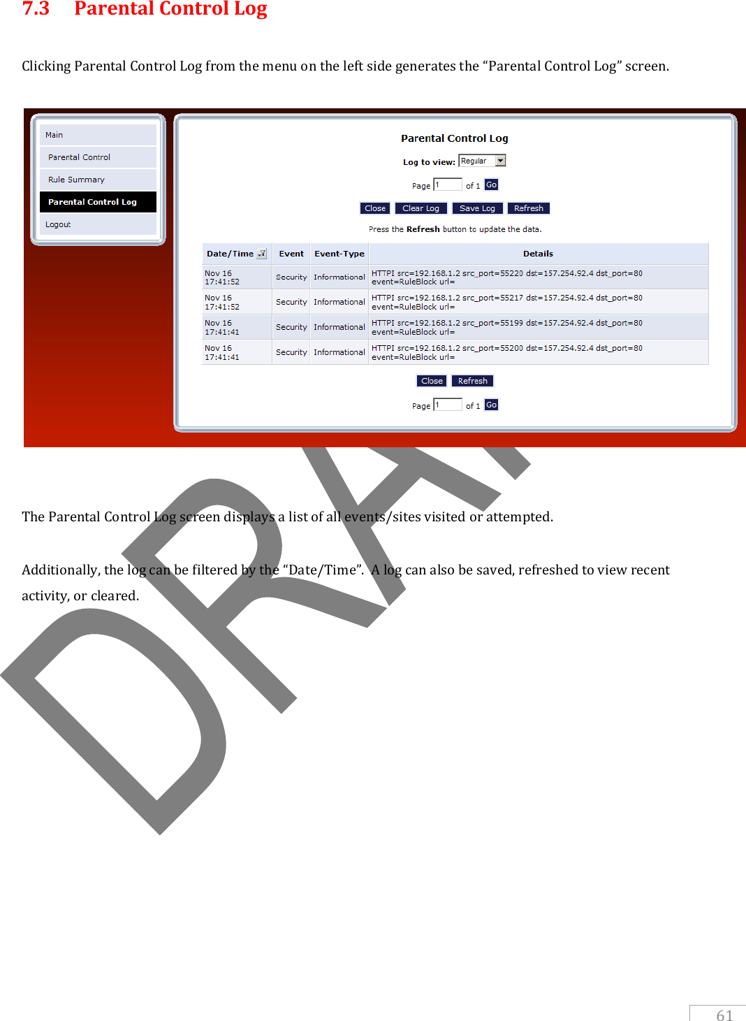
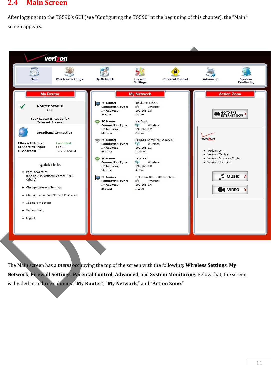
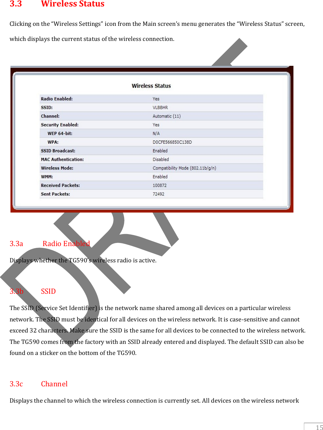
![Banister, Valerie [Type the abstract of the document here. The abstract is typically a short summary of the contents of the document.] Setup and User Guide TG590](https://usermanual.wiki/Technicolor-Delivery-Technologies-Belgium/TG590.User-Manual-1/User-Guide-1388210-Page-1.png)
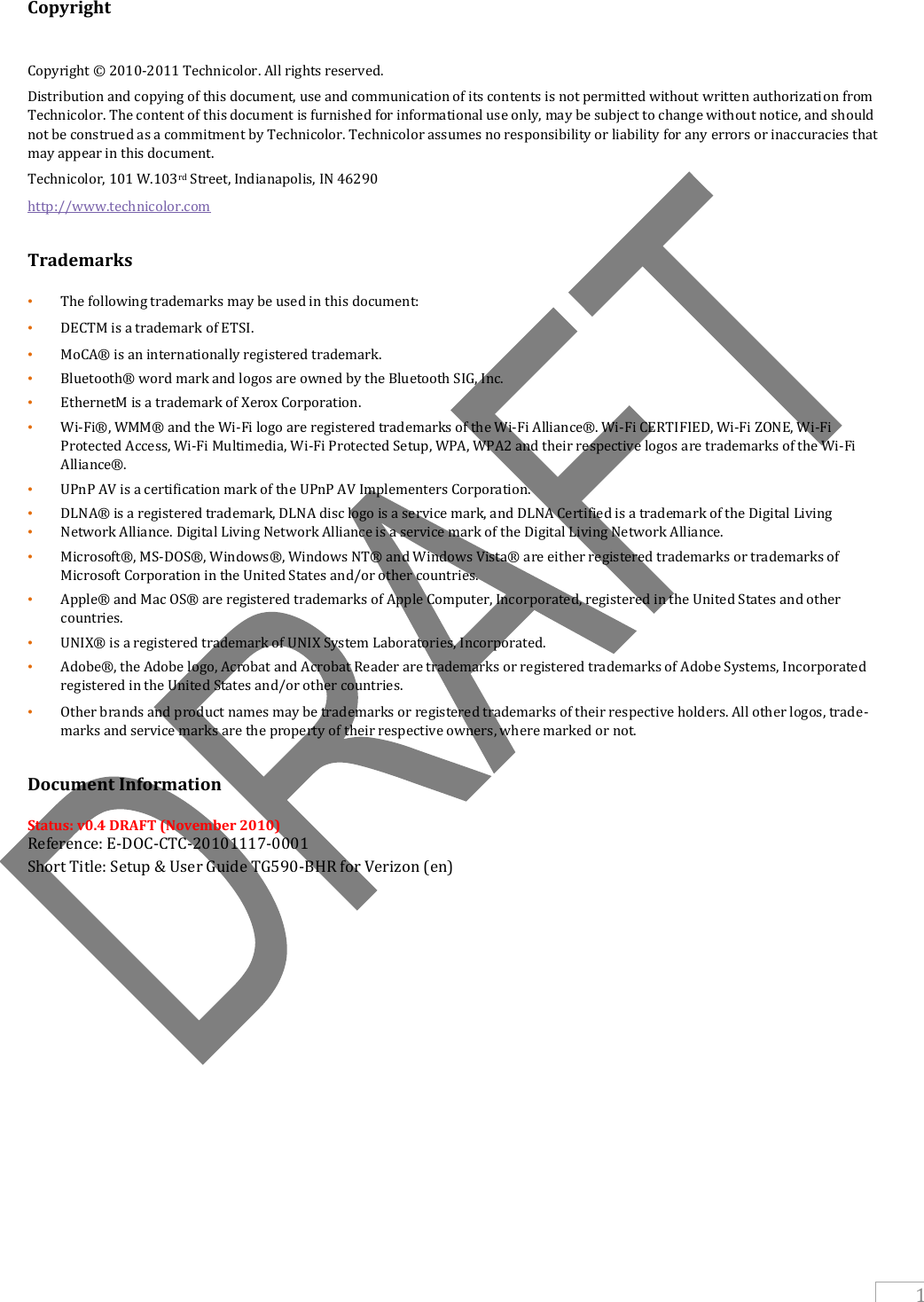

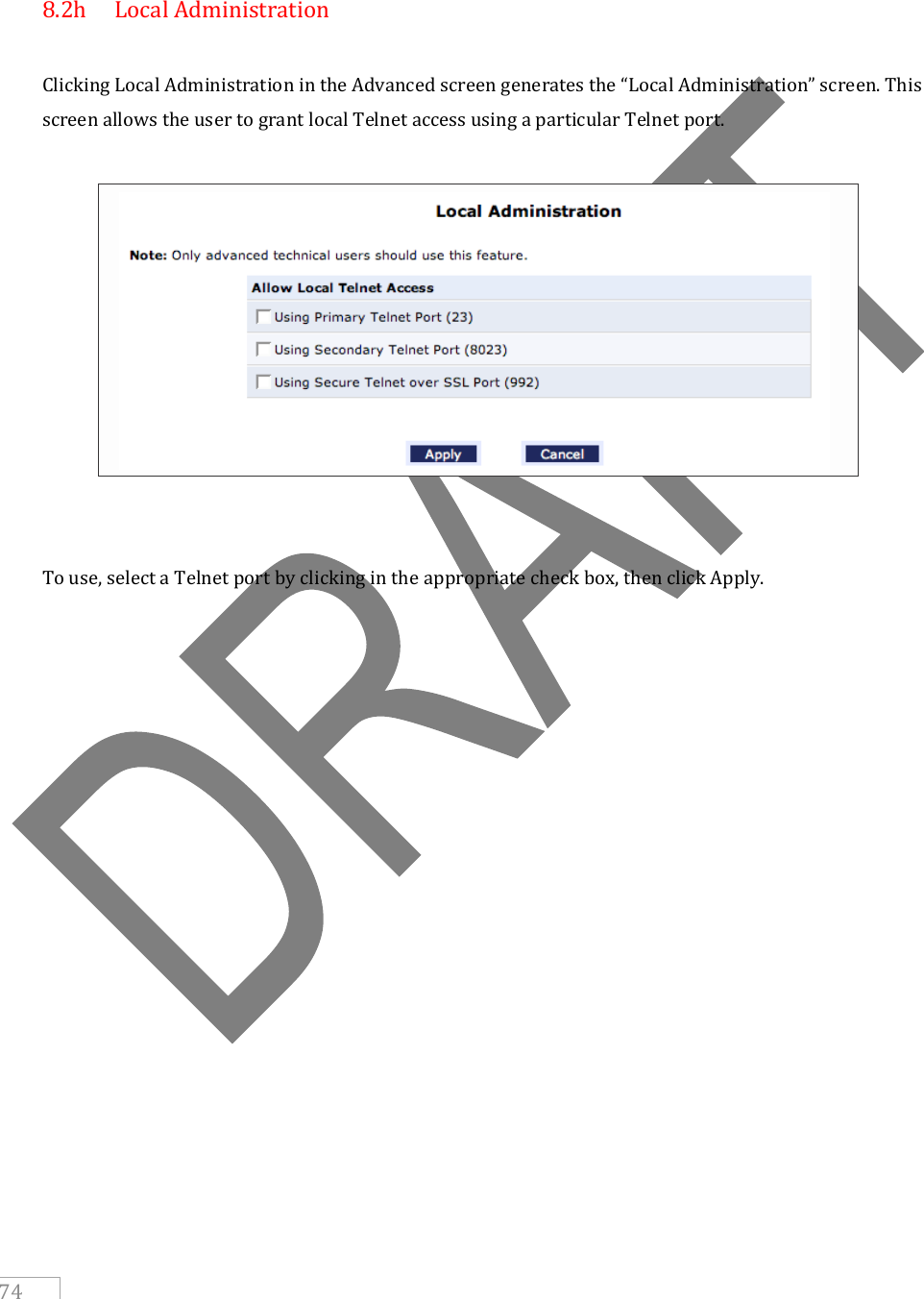
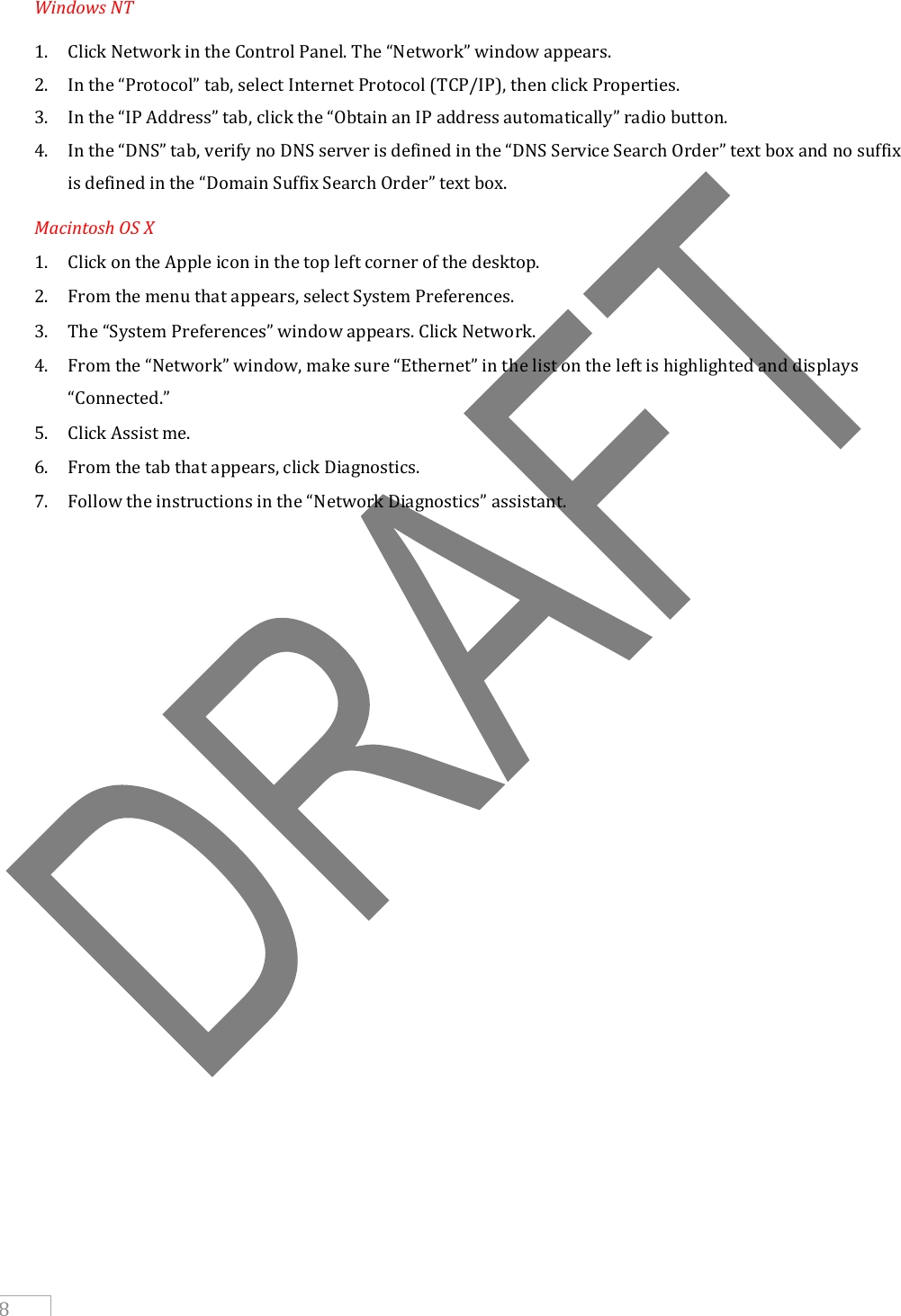
![5 2.1b Rear Panel The rear panel of the TG590 has seven ports (Reset, Power, LAN Ethernet [4], COAX, and WAN Ethernet), a Power switch, a Reset button, and a wireless antenna. (Listed in order from left to right) Reset Button To restore the TG590’s factory default settings, press and hold the Reset button for approximately five seconds. The reset process will start about ten seconds after releasing the button. When the TG590 resets, all the lights on the front panel turn off, and then some of the lights start flashing. The TG590 has completed its reset process when the Power light glows steadily green. Caution! Do not unplug the Power cord from the TG590 during the reset process. Doing so may result in the loss of the TG590’s configuration information. If this occurs, reset the TG590 again. Coax The Coax port connects the TG590 to the ISP or other devices using a coaxial cable. Power The Power port connects the TG590 to an electrical wall outlet via the Power cord. Power Switch The Power switch powers the TG590 on and off. LAN Ethernet Ports (4) The LAN Ethernet ports connect devices to the TG590 via Ethernet cables to create a local area network (LAN). The LAN Ethernet ports are 10/100 Mbps auto-sensing ports, and either a straight through or crossover Ethernet cable can be used when connecting devices to the ports. WAN Ethernet Port The WAN Ethernet port connects the TG590 to the ISP using an Ethernet cable.](https://usermanual.wiki/Technicolor-Delivery-Technologies-Belgium/TG590.User-Manual-1/User-Guide-1388210-Page-17.png)
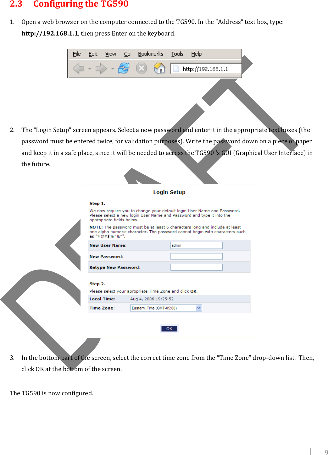

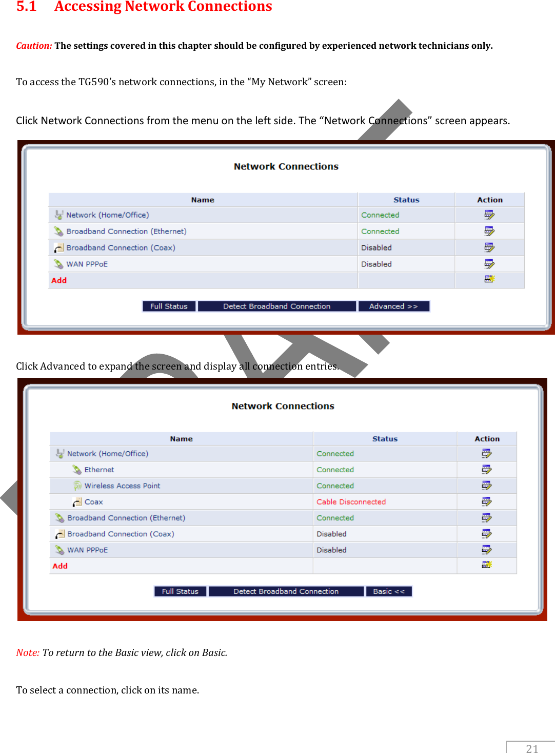
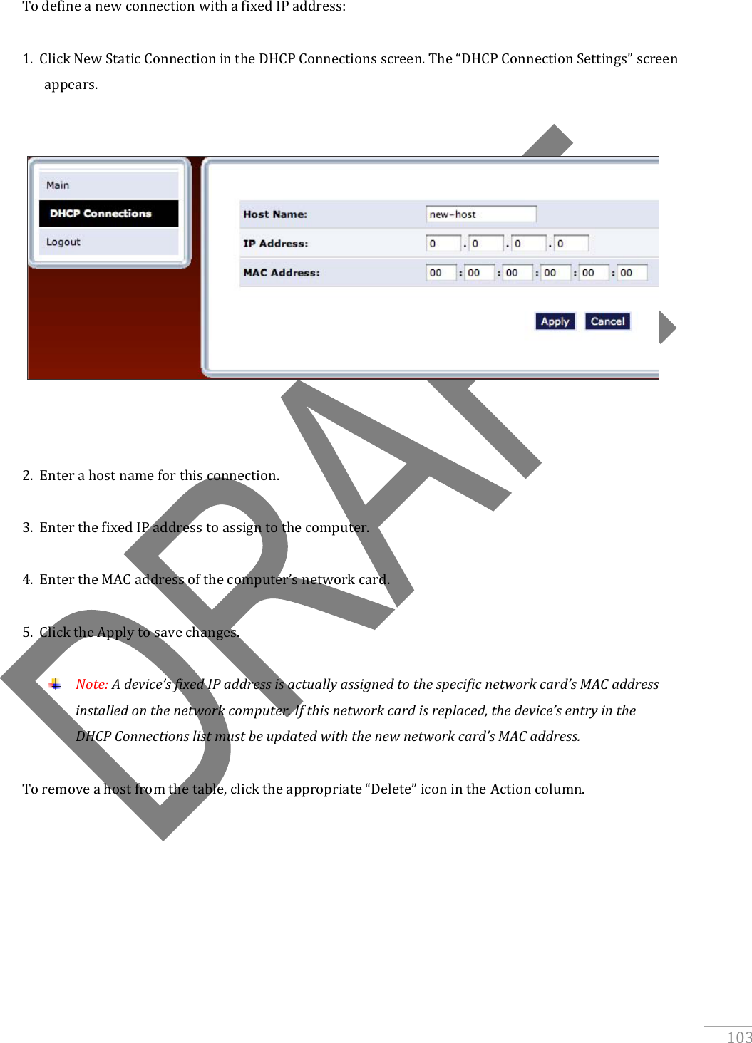
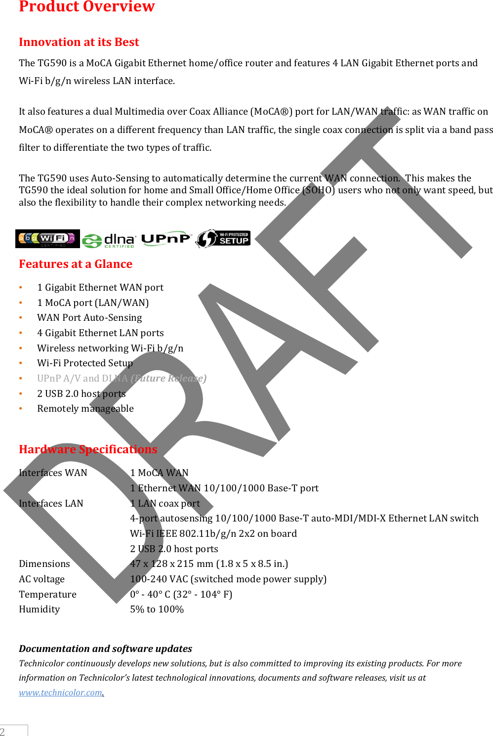
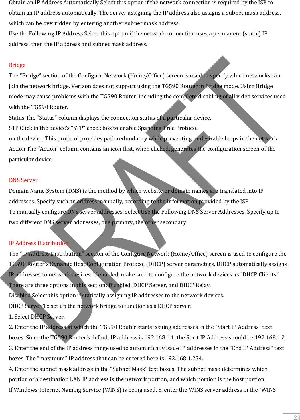
![22 The remainder of this chapter describes the various network connections available on the TG590. 5.2 Network (Home/Office) Connection Select Network (Home/Office) in the Network Connections screen to generate the “Network (Home/Office) Properties” screen. This screen displays a list of the local network’s properties. The only modifications that can be made from this screen are disabling the connection (by clicking Disable) or renaming the connection (by entering a new name in the “Rule Name” text box). Note: When a network is disabled, its formerly underlying devices will not be able to get the DHCP address from the network interface to which they were connected. Using Network Connections The Network (Home/Office) connection is used to combine several network devices under one virtual network. For example, a home/office network can be created for Ethernet and other network devices. 5.2a Configuring the Home/Office Network Click Settings in the “Network (Home/Office) Properties” screen to generate the “Configure Network (Home/Office)” screen. General The top part of the Configure Network (Home/Office) screen displays general communication parameters. We recommend not changing the default values in this section unless familiar with networking concepts. Status Displays the connection status of the network. “When should this rule occur? Displays when the rule is active. To schedule rules, see the “Advanced Settings” chapter. Network Select the type of connection being configured from the drop-down list (options: Broadband Connection, Network [Home/Office], or DMZ). Connection Type Displays the type of connection. Physical Address Displays the physical address of the network card used for the network. MTU MTU (Maximum Transmission Unit) specifies the largest packet size permitted for Internet transmission. “Automatic” sets the MTU at 1500. Other choices include “Automatic by DHCP,” which sets the MTU according to the DHCP connection, and “Manual,” which allows the MTU to be set manually. Internet Protocol This section has three options: No IP Address, Obtain an IP Address Automatically, and Use the Following IP Address. No IP Address Select this option if the connection will have no IP address. This is useful if the connection operates under a bridge.](https://usermanual.wiki/Technicolor-Delivery-Technologies-Belgium/TG590.User-Manual-1/User-Guide-1388210-Page-34.png)
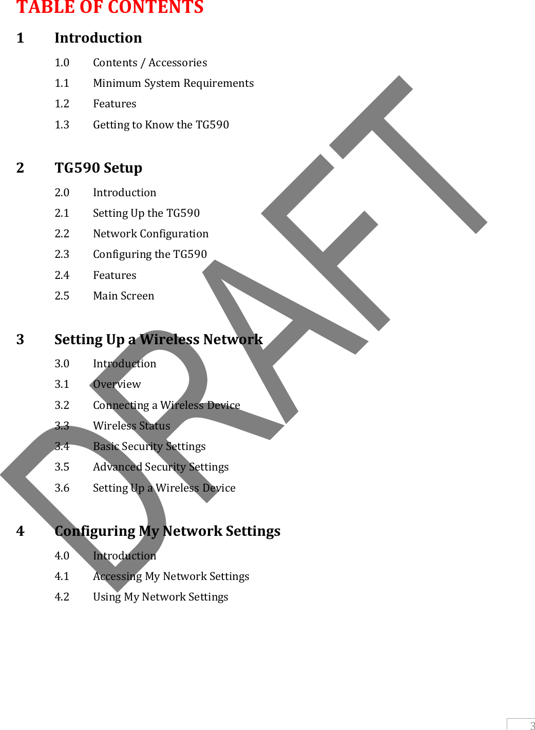
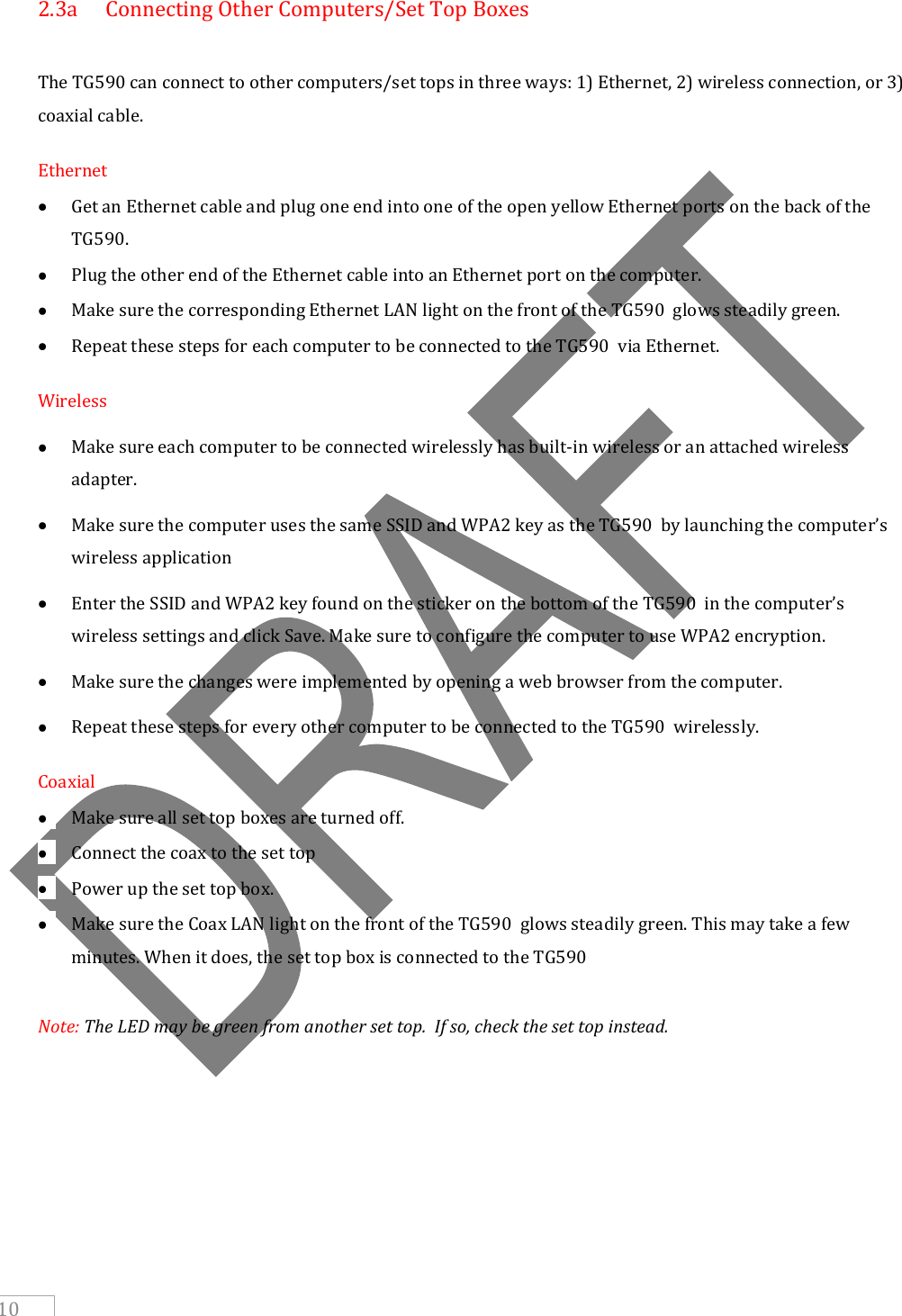
![24 Server” text boxes. 6. Enter the amount of time a network device will be allowed to connect to the TG590 Router with its currently issued dynamic IP address in the “Lease Time in Minutes” text box. 7. Click in the “Provide Host Name If Not Specified by Client” check box to have the TG590 Router automatically assign network devices with a host name, in case a host name is not provided by the user. DHCP Relay Select this option to have the TG590 Router function as a DHCP relay, and enter the IP address in the screen that appears. Routing The TG590 Router can be configured to use static or dynamic routing. Dynamic routing automatically adjusts how packets travel on the network, while static routing specifies a fixed routing path to neighboring destinations. There are two options in the “Routing” section of the Configure Network (Home/Office) screen: Basic or Advanced. Basic Select this option for basic routing operation. Advanced To set up the TG590 Router’s network bridge for advanced routing: 1. Select Advanced from the “Routing” drop-down menu. 2. Enter a device metric in the “Device Metric” text box. The device metric is a value used by the TG590 Router to determine whether one route is superior to another, considering parameters such as bandwidth and delay time. 3. Click in the “Default Route” check box to define this device as a default route. 4. Click in the “Multicast - IGMP Proxy Internal” check box to activate multicasting. Routing Table Clicking New Route generates the “New Route” window, where a new route can be configured. Additional IP Addresses Clicking New IP Address generates the “Additional IP Address Settings” screen, where additional IP addresses can be created to access the TG590 Router via the Network (Home/Office) connection. 5.3 Ethernet Connection An Ethernet connection connects computers to the TG590 Router using Ethernet cables, either directly or via network hubs and switches. Click Ethernet in the Network Connections screen (if needed, click Advanced at the bottom of the screen to reveal the “Ethernet” link below “Network [Home/Office]”) to generate the “Ethernet Properties” screen. This screen displays a list of the connection’s properties. The only modifications that can be made from this screen are disabling the connection (by clicking Disable) or renaming the connection (by entering a new name in the “Rule Name” text box).](https://usermanual.wiki/Technicolor-Delivery-Technologies-Belgium/TG590.User-Manual-1/User-Guide-1388210-Page-36.png)
![25 Note: If disabling the connection, the TG590 Router must be rebooted for the change to take effect. 5.3a Configuring the Ethernet Connection Click Settings at the bottom-right of the Ethernet Properties screen to generate the “Configure Ethernet” screen. General The top part of the Configure Ethernet screen displays general communication parameters. We recommend not changing the default values in this section unless familiar with networking concepts. Status Displays the connection status of the Ethernet switch. When should this rule occur? Displays when the rule is active. To schedule rules, see the “Advanced Settings” chapter. Network Select the type of connection being configured from the drop-down list (Network [Home/Office], Broadband Connection, or DMZ). Connection Type Displays the type of connection. Physical Address Displays the physical address of the network card used for the network. MTU MTU (Maximum Transmission Unit) specifies the largest packet size permitted for Internet transmission. “Automatic” sets the MTU at 1500. Other choices include “Automatic by DHCP,” which sets the MTU according to the DHCP connection, and “Manual,” which allows the MTU to be set manually. Additional IP Addresses Clicking New IP Address generates the “Additional IP Address Settings” screen, where additional IP addresses can be created to access the TG590 Router via the Ethernet connection. HW Switch Ports This section displays the connection status of the TG590 Router’s four Ethernet ports. Clicking on a connection’s “Action” icon (in the column on the right) generates the “Port VLANs” screen, where ingress and egress policies can be edited.](https://usermanual.wiki/Technicolor-Delivery-Technologies-Belgium/TG590.User-Manual-1/User-Guide-1388210-Page-37.png)
![26 5.4 Coax Connection A Coax connection connects devices (such as set-top boxes) to the TG590 Router using a coaxial cable. Click Coax in the Network Connections screen (if needed, click Advanced at the bottom of the screen to reveal the “Coax” link below “Network [Home/Office]”) to generate the “Coax Properties” screen. This screen displays a list of the connection’s properties. The only modifications that can be made from this screen are disabling the connection (by clicking Disable) or renaming the connection (by entering a new name in the “Name” text box). Note: If disabling the connection, the TG590 Router must be rebooted for the change to take effect. 5.4a Configure Coax Click Settings at the bottom-right of the Coax Properties screen generates the “Configure Coax” screen. General The top part of the Configure Coax screen displays general communication parameters. We recommend not changing the default values in this section unless familiar with networking concepts. Status Displays the status of the coax connection. When should this rule occur? Displays when the rule is active. To schedule rules, see the “Advanced Settings” chapter Network Displays the type of network. Connection Type Displays the type of connection. Physical Address Displays the physical address of the network card used for the network. MTU MTU (Maximum Transmission Unit) specifies the largest packet size permitted for Internet transmission. “Automatic” sets the MTU at 1500. Other choices include “Automatic by DHCP,” which sets the MTU according to the DHCP connection, and “Manual,” which allows the MTU to be set manually. Coax Link Set up the coax link options in this section of the Configure Coax screen. Options include Channel, Privacy, and Password. Channel Select the Channel from the drop-down list (select from 1-6, or “Automatic”). Privacy Toggle “Privacy” by clicking in the “Enabled” check box. If Privacy is activated, all devices connected via coaxial cable must use the same password. We recommend leaving the Privacy option deactivated. Password Enter the Coax Link password in this text box. Additional IP Addresses Clicking New IP Address generates the “Additional IP Address Settings” screen, where additional IP addresses can be created to access the TG590 Router via the](https://usermanual.wiki/Technicolor-Delivery-Technologies-Belgium/TG590.User-Manual-1/User-Guide-1388210-Page-38.png)
![27 Coax Link Ethernet connection. Coax Connection Status Click Go to LAN Coax Stats to generate the “Coax Connection Status” screen, which gives an overview of all the devices connected to the TG590 Router via coaxial cable. 5.5 Broadband Ethernet Connection A Broadband Ethernet connection connects the TG590 Router to the Internet using an Ethernet cable. Click Broadband Connection (Ethernet) from the Network Connections screen to generate the “Broadband Connection (Ethernet) Properties” screen. This screen displays a list of the connection’s properties. The only modifications that can be made from this screen are disabling the connection (by clicking Disable) or renaming the connection (by entering a new name in the “Rule Name” text box). Note: If disabling the connection, the TG590 Router must be rebooted for the change to take effect. 5.5a Configuring the Broadband Ethernet Connection Click Settings at the bottom-right of the Broadband Connection (Ethernet) Properties window to generate the “Configure Broadband Connection (Ethernet)” screen. General The top part of the screen displays general communication parameters. We recommend not changing the default values in this section unless you are familiar with networking concepts. Status Displays the status of the Ethernet connection (“Down,” “Connected,” etc.) Schedule Displays when the rule is active. To configure rules, see the “Advanced Settings” chapter. Network Select the type of connection being configured from the drop-down list (options: Network [Home/Office], Broadband Connection, or DMZ). Connection Type Displays the type of connection. Since this is an Ethernet Connection, “Ethernet” is displayed. Physical Address Displays the physical address of the network card used for the network. MTU MTU (Maximum Transmission Unit) specifies the largest packet size permitted for Internet transmission. “Automatic, sets the MTU at 1500. Other choices include “Automatic by DHCP,” which sets the MTU according to the](https://usermanual.wiki/Technicolor-Delivery-Technologies-Belgium/TG590.User-Manual-1/User-Guide-1388210-Page-39.png)