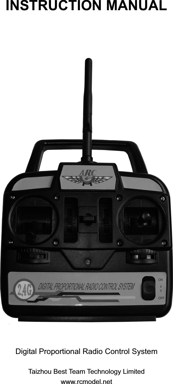
Taizhou Best Team Technology ATTX Remote Control Transmitter User Manual

Taizhou Best Team Technology Limited Remote Control Transmitter

User Manual

INSTRUCTION MANUAL Digital Proportional Radio Control System Taizhou Best Team Technology Limited www.rcmodel.net
SAFETY NOTES Please read through the instructions carefully before using this radio. Pay much attention to all precautions and warnings to ensure the safest operation. WARNINGS Do not fly in the rain or at night. Water can permanently damage many of the components in the radio system, possibly causing loss of the control and a crash. Only fly at designated R/C flying fields. Fly at safe distances away from other people, objects in the air, buildings, electrical lines, or any other object which could possible impede safe flying. Failure to do so could cause a crash and possibly bodily harm and physical damage to other property. Always test the radio system before use. Make sure the operation of each channel in the radio is in the proper direction. If a channel does not accurately respond according to the transmitter input, do not fly the model. Check for and correct improperly functioning equipment before use. Failure to ensure proper radio operation before flight could result in a crash. During flight preparations, be certain to place the transmitter on its back when on the ground, to prevent it from accidentally falling over and inadvertently moving the throttle stick to high speed.Do not allow fuel or oil on the plastic parts. Some plastics may melt when exposed to such material.Before turning on the transmitter, adjust the throttle stick to minimum speed position. After stopping the engine turn “OFF”, the transmitter power switch, then turn “Off” the transmitter power switch. Failure to follow this order could cause the engine to go to full throttle and cause an injury. Do not make adjustments to the radio system while the engine is running unless absolutely necessary. Failure to do so could cause the engine to accidentally go to high speed and cause an injury. The transmitter is designed for use with 8 dry cell (Non-rechargeable) AA size alkaline batteries or rechargeable NiMh cells (available separately). If using rechargeable batteries, please follow the charging instructions supplied by the manufacturer of the batteries.     Never attempt to charge non-chargeable alkaline dry cell batteries as there is a risk of fire, damage and personal injury. Always full charge the transmitter and receiver battery before each flight. Failure to do so could cause an inadvertent power failure and a crash. Use the charger supplied with this supplied with this radio. If using another charger, do not overcharge the battery, as it could cause burns, fire, injury or other equipment damage. Do not short circuit the battery terminals, as arcing, overheating or fire could result. Do not leave the radio system, batteries, model helicopter or other equipment within the reach of children. Do not overheat or throw the batteries into a fire. Leaking electrolyte from the battery could cause injury, such as burns or blindness. In case of emergency, immediately flush you eyes, skin or cloths with plenty of water and see a doctor. Recycle the battery when no longer in usable condition. Store the radio with all NiMh batteries in the
discharged state and be certain to full charge the batteries just prior to use. Do not store the radio system in extreme heat or cold, in direct sunlight, in high humidity, in high vibration environments or in dusty areas. NAME AND HANDLING OF EACH PART           Servo reversing switches (Option Function)Switches that reverse the direction of operation of the servosThe lower position is the normal side and the upper position is the reverse side.Channel display                                 Operating direction displayAIL. : Aileron(CH1)                               REV. : Reverse sideELE. : Elevator(CH2)                            NOR. : NormalTHR. : throttle(CH3)RUD. :Rudder(CH4)Power switchin the upper position,the power is turned on. LED Power onHook Ailerontrim leverRudder trimleverThrottle (model 1)Elevator (model 2)/Aileron stickElevator (model 1)Throttle (model 2)/rudder stickCarrying bar 2.4G AntennaThrottle trim lever(model 1)Elevator trim lever(model 2)Elevator trim lever(model 1)Throttle trim lever(model 2)Battery Box CoverUse when replacing the batteryBattery BoxCharging JackCharging jack when the transmitterwas converted to NiMh battery system.
Aileron Control (CH1): When the aileron stick is mover to the right, the right aileron is raised and the left aileron is raised and the left aileron is lowered and the helicopter banks to the right. When the aileron stick is moved to the left, the ailerons move in the opposite direction and the helicopter banks left. To level the helicopter, the aileron stick must be move in the opposite direction and back to center. Elevator Control (CH2): When the elevator stick is pulled back, the tail elevator is raised and the tail of the helicopter is forced down, thus causing the model to climb (Up Operation), When the elevator stick is pushed forward, the elevator is lowered, the tail of the model is forced up, thus causing the model to descend (Down Operation). Throttle Control (CH3): When the throttle stick is pulled back, the engine throttle lever arm moves to the slow (Low Speed) side. When the throttle stick is pushed forward, the throttle lever arm moves to the High (High Speed) side. Rudder Control (CH4): When the rudder stick is moved to the right, the rudder moves to the right and nose points to the right, thus causing the model to turn right. When the rudder stick is moved to the left, the rudder moves to the leftˈand the nose points to the left, thus causing the model to turn left. SERVO INSTRLLATION All servos should be mounted as shown in the model’s instructions. Use the rubber grommets, screws and brass eyelets supplied when mounting your servos.   Do not over-tighten the mounding screws. The servos should be able to move slightly to compensate for engine vibration. For each servo, use a servo horn long enough to accommodate the entire range of movement for that particular control.   When mounting the servos, make sure the pushrods are not too loose or bind in anyway. Pushrods should be capable of operating the full range of the servo. This can be tested by moving the transmitter sticks to maximum positions several times while observing the movement of the control services. If a servo is binding or sticks in flight, a greater current drain on the battery is applied, thus shortening the flight time of the model. Binding can also cause damage to the servo and loose linkages could   result in poor control of the model.   Because there are varieties of specific applications for servos in R/C modeling, different servos are designed for different applications.REVCEIVER INSTALLATION After the receiver and servos are mounted in your model, connect the receiver to servos and switch harness per the diagram below. Always insert the servo and battery or switch harness connector into the receiver firmly, to ensure solid physical and electrical connections are made.  Turn on the transmitter, then the receiver switch harness. Make sure all servos operate ELE.AIL.THR.RUD.Battery connector
according to the movement of the transmitter sticks. Center all trim levers, turn off the receiver switch harness, then the transmitter and be careful not to move the servo arms from their centered position during installation. The servo connectors are keyed to prevent improper connection, but do pay close attention when connecting them to the receiver. The black wire goes toward the outside edge of the receiver case. Mount the switch harness to the side of the fuselage away from the engine exhaust (refer to your model’s instruction manual). Connect the red plug to the receptacle on the receiver marked B for battery.   BINDINGThe receiver must be bound to the transmitter before it will operate. Binding is the process of teaching the receiver the specific code of the transmitter so it will connect to that specific transmitter. Once bound, the receiver will only connect to the transmitter when the previously bound model memory is selected. If another model memory is selected, the receiver will not connect. This feature prevents flying a model using the wrong model memory. 1.    Switch on the transmitter, ensuring that the throttle control stick at its lowest position.   2.    Connect the receiver battery to the receiver and wait until the Power Indicator LED on the receiver glows solid green. 3. Press and hold the Binding Switch on the receiver for approximately 5 seconds until the Binding Indicator LED on the receiver goes solid green, indicating the binding finished.   RANG & BATTERY TEST It is very important to check the transmitter will operate the model satisfactorily at maximum range. 1. In order to do this, place the model on the ground and walk away from it whilst operation the swashplate controls. Check that the servo in the model operate without interference up to a distance of 33m.   2. Check that the transmitter battery status LED is showing a bright red. Do not fly if the LED begins to flash, as the batteries need to be replaced or recharged. . ADJUSTMENTS The operating direction, neutral position and steering angle of each servo are adjusted. Caution: The basic linkage and adjustments of the fuselage conform to the fuselage design drawing. Be sure that center of gravity is at the prescribed position. Before making and adjustments, set all the servo reverser switches on the front of the transmitter to the lower (NOR) position (Switch the switches with a small screwdriver). Turn on the transmitter and receiver power switches and make the following adjustments. Power Indicator Binding Switch Binding Indicator
1. Servo Reverser Switch (Option Function): Check the direction of each servo. If a servo operates in the wrong direction, switch its SERVO REVERSER switch (The direction of operation can be changed without changing the linkage).Note that the direction of the aileron servo is easily mistaken. 2. Neutral Adjustment: Check the aileron, elevator and rudder neutral adjustment and left-right (up-down) throw. Check that when trimmed to the center, the servo horn is perpendicular to the servo and check the neutral position of the fuselage control surfaces (aileron, elevator, rudder, etc.). If the neutral position has changed, reset it by adjusting the length of the rod with the linkage rod adjuster. When the throw is unsuitable (different from steering angle specified by the kit instruction manual), adjust it by changing the servo horn and each control surface horn rod.   3. Check the engine throttle (speed adjustment) linkage.Change the servo horn installation position and hole position so that the throttle is opened fully when the throttle stick is set to HIGH (forward) and is closed fully when the throttle stick and throttle stick and throttle trim are set for maximum slow (backward position and lower position, respectively). 4. After all the linkages have been connected, recheck the operating direction throw, etc. Before flight, adjust the model in accordance with the kit and engine instruction manuals. 5. Fly the model and trim each servo.   USING OTHER FUNCTIONS LEVER SPRING TENSION ADJUSTMENT The stick spring strength can be adjusted. The operation feel of the throttle sticks can be individually adjusted. 1. Remove the four transmitter rear case screws and remove the rear case. 2. Adjust the spring strength by turning the screw of the channel you want to adjust. 3. Close the rear case and tighten the four screws.
GLOSSARY The following defines the symbols and terms are used in this instruction manual. Aileron (AIL): Control surface at the left and right side of the main wing of the model. It usually controls turning of the model. Channel: Represents the number of control systems. It can also represent the number of servos that are operated. Down: Means down elevator. It is the direction in which the trailing edge of the elevator is pointing down. Elevator (ELE): Control surface that moves up and down on the horizontal stabilizer of an aircraft. It usually controls up and down. Linkage: Mechanism that connects the servos and the fuselage control surfaces. Neutral: Means the neutral position. It is the state in which a transmitter stick returns to the center when not operated. Normal (NOR): For the servo reversing function, it is the normal side, the opposite side is the reverse side. Rudder (RUD): Tail control surface that controls the direction of the aircraft.   Reverse (REV): With the servo reversing function, this is used to mean the reverse side. The opposite side is the normal side. Rod: A bar that connects the servos and the fuselage control surfaces. Servo Horn: A part that is installed to the shaft of a servo and changes the rotating motion of the servo to linear motion and transmits the linear motion to a rod. Servo horns come in various shapes. Stick: Rod for operating the transmitter. Trim: A device that fine adjusts the neutral point of each servo for safe flying. It is a mechanism that corrects bad tendencies of the aircraft. Up: Means up elevator. Direction in which the trailing edge of the elevator is pointing up. FCC STATEMENT 1. This device complies with Part 15 of the FCC Rules. Operation is subject to the following two conditions: (1) This device may not cause harmful interference, and (2) This device must accept any interference received, including interference that may cause undesired operation. 2. Changes or modifications not expressly approved by the party responsible for compliance could void the user’s authority to operate the equipment.
NOTE: This equipment has been tested and found to comply with the limits for a Class B digital device, pursuant to Part 15 of the FCC Rules. These limits are designed to provide reasonable protection against harmful interference in a residential installation. This equipment generates, uses and can radiate radio frequency energy and, if not installed and used in accordance with the instructions, may cause harmful interference to radio communications. However, there is no guarantee that interference will not occur in a particular installation. If this equipment does cause harmful interference to radio or television reception, which can be determined by turning the equipment off and on, the user is encouraged to try to correct the interference by one or more of the following measures:-- Reorient or relocate the receiving antenna. -- Increase the separation between the equipment and receiver. -- Connect the equipment into an outlet on a circuit different from that to which the receiver is connected. -- Consult the dealer or an experienced radio/TV technician for help.

Navigation menu