TOSHIBA TEC Singapore S-0601 Dot Printer User Manual 10
TOSHIBA TEC Singapore Pte Ltd Dot Printer Users Manual 10
Contents
- 1. Users Manual 1
- 2. Users Manual 2
- 3. Users Manual 3
- 4. Users Manual 4
- 5. Users Manual 5
- 6. Users Manual 6
- 7. Users Manual 7
- 8. Users Manual 8
- 9. Users Manual 9
- 10. Users Manual 10
- 11. Users Manual 11
- 12. Users Manual 12
- 13. Users Manual 13
- 14. Users Manual 14
- 15. Users Manual 15
- 16. Users Manual 16
- 17. Users Manual 17
- 18. Users Manual 18
Users Manual 10
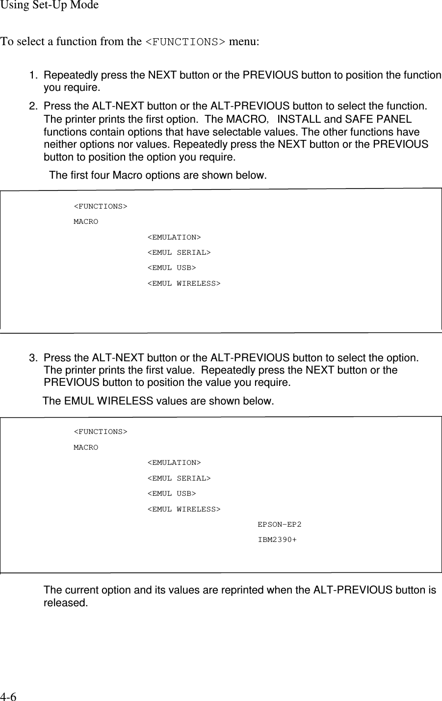
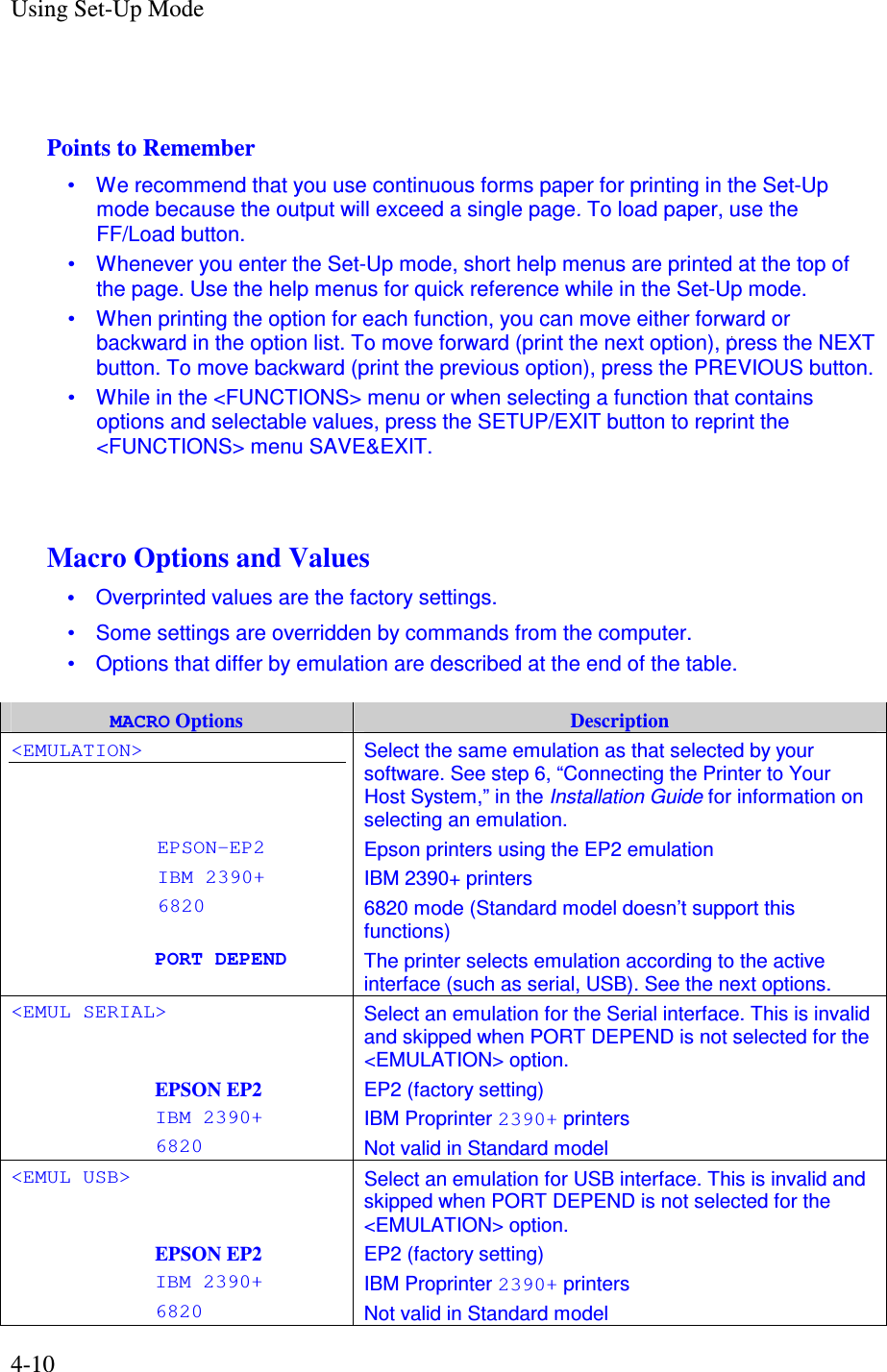
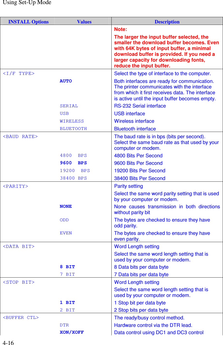
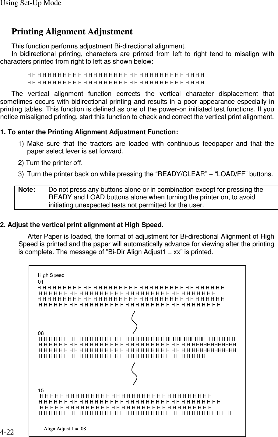
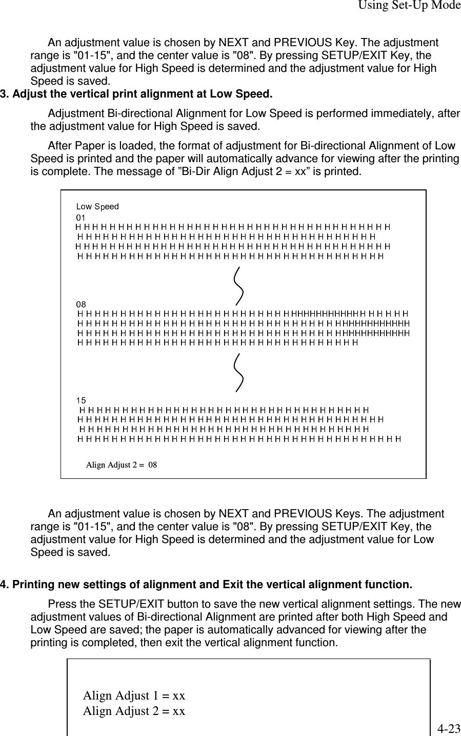
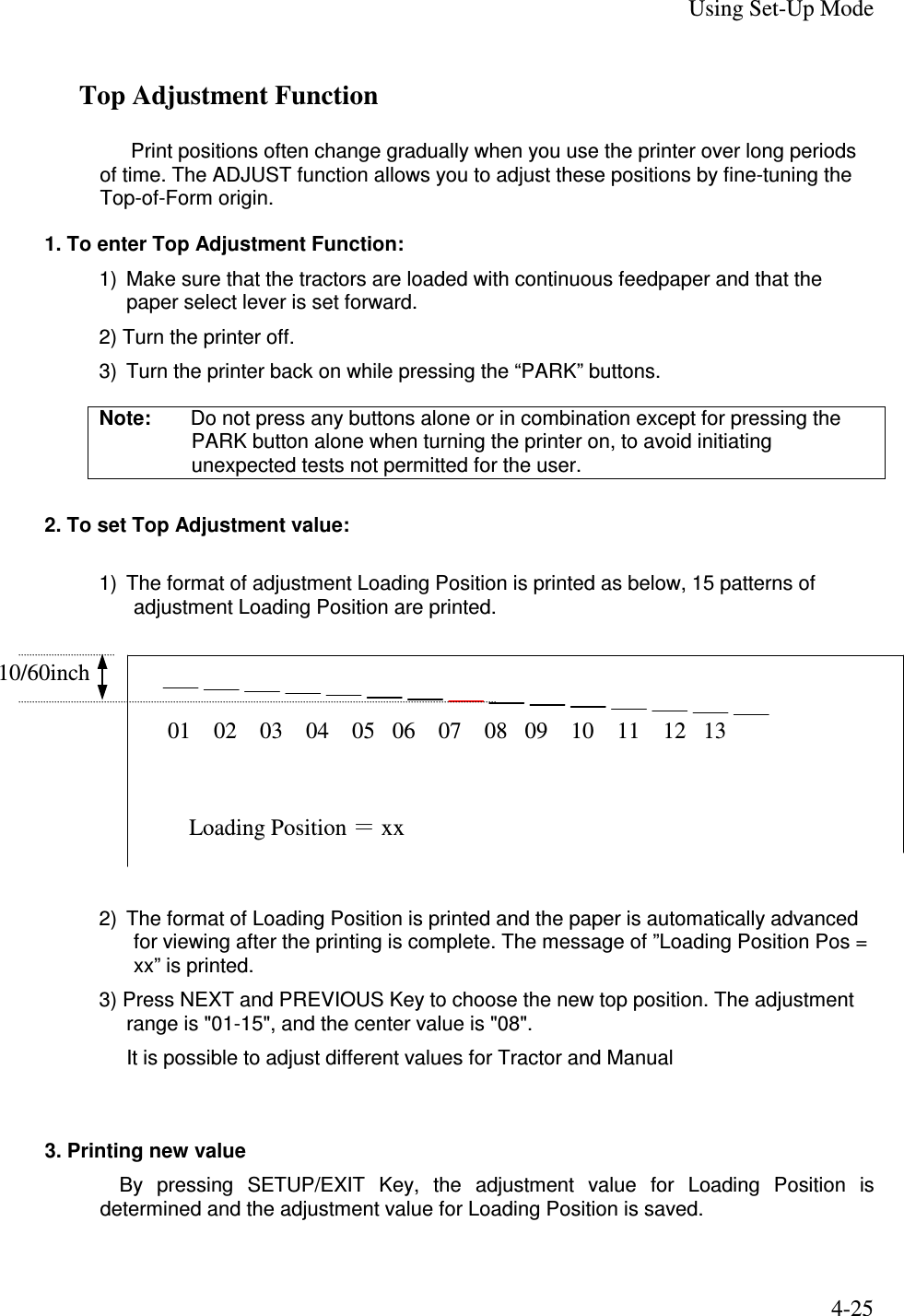
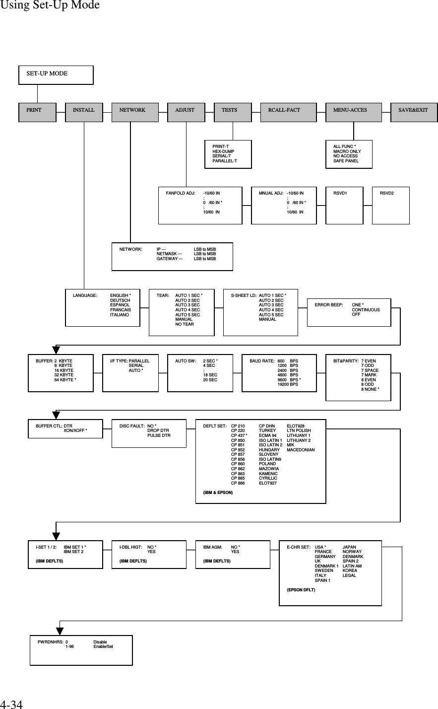
![Using Set-Up Mode 4-20 Printing Test Function The printing test function prints test pages independently of your computer to check printing operations and quality. It does not check the interface between the computer and the printer. The printing test prints all of the characters available in the ASCII character set. 1. To enter the Printing Test mode: 1) Make sure that the tractors are loaded with continuous feedpaper and that the paper select lever is set forward. 2) Turn the printer off. 3) Turn the printer back on while pressing the “LOAD/FF” button. Note: Do not press any buttons alone or in combination except for pressing the LOAD button alone when turning the printer on, to avoid initiating unexpected tests not permitted for the user. 2. The printer starts to print rolling ASCII data as shown below. 3. To exit the Printer Configuration mode: Printing Test mode is continues until power OFF. _!"#$%&'()*+,-./0123456789:;<=>?@ABCDEFGHIJKLMNOPQRSTUVWXYZ[ !"#$%&'()*+,-./0123456789:;<=>?@ABCDEFGHIJKLMNOPQRSTUVWXYZ[\ "#$%&'()*+,-./0123456789:;<=>?@ABCDEFGHIJKLMNOPQRSTUVWXYZ[\] #$%&'()*+,-./0123456789:;<=>?@ABCDEFGHIJKLMNOPQRSTUVWXYZ[\]^ $%&'()*+,-./0123456789:;<=>?@ABCDEFGHIJKLMNOPQRSTUVWXYZ[\]^_ %&'()*+,-./0123456789:;<=>?@ABCDEFGHIJKLMNOPQRSTUVWXYZ[\]^_` &'()*+,-./0123456789:;<=>?@ABCDEFGHIJKLMNOPQRSTUVWXYZ[\]^_`a '()*+,-./0123456789:;<=>?@ABCDEFGHIJKLMNOPQRSTUVWXYZ[\]^_`ab ()*+,-./0123456789:;<=>?@ABCDEFGHIJKLMNOPQRSTUVWXYZ[\]^_`abc )*+,-./0123456789:;<=>?@ABCDEFGHIJKLMNOPQRSTUVWXYZ[\]^_`abcd . . . . . . . . . _!"#$%&'()*+,-./0123456789:;<=>?@ABCDEFGHIJKLMNOPQRSTUVWXYZ[ !"#$%&'()*+,-./0123456789:;<=>?@ABCDEFGHIJKLMNOPQRSTUVWXYZ[\ "#$%&'()*+,-./0123456789:;<=>?@ABCDEFGHIJKLMNOPQRSTUVWXYZ[\] #$%&'()*+,-./0123456789:;<=>?@ABCDEFGHIJKLMNOPQRSTUVWXYZ[\]^ $%&'()*+,-./0123456789:;<=>?@ABCDEFGHIJKLMNOPQRSTUVWXYZ[\]^_ %&'()*+,-./0123456789:;<=>?@ABCDEFGHIJKLMNOPQRSTUVWXYZ[\]^_` &'()*+,-./0123456789:;<=>?@ABCDEFGHIJKLMNOPQRSTUVWXYZ[\]^_`a '()*+,-./0123456789:;<=>?@ABCDEFGHIJKLMNOPQRSTUVWXYZ[\]^_`ab](https://usermanual.wiki/TOSHIBA-TEC-Singapore/S-0601.Users-Manual-10/User-Guide-650724-Page-20.png)
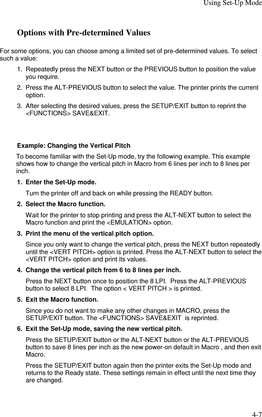
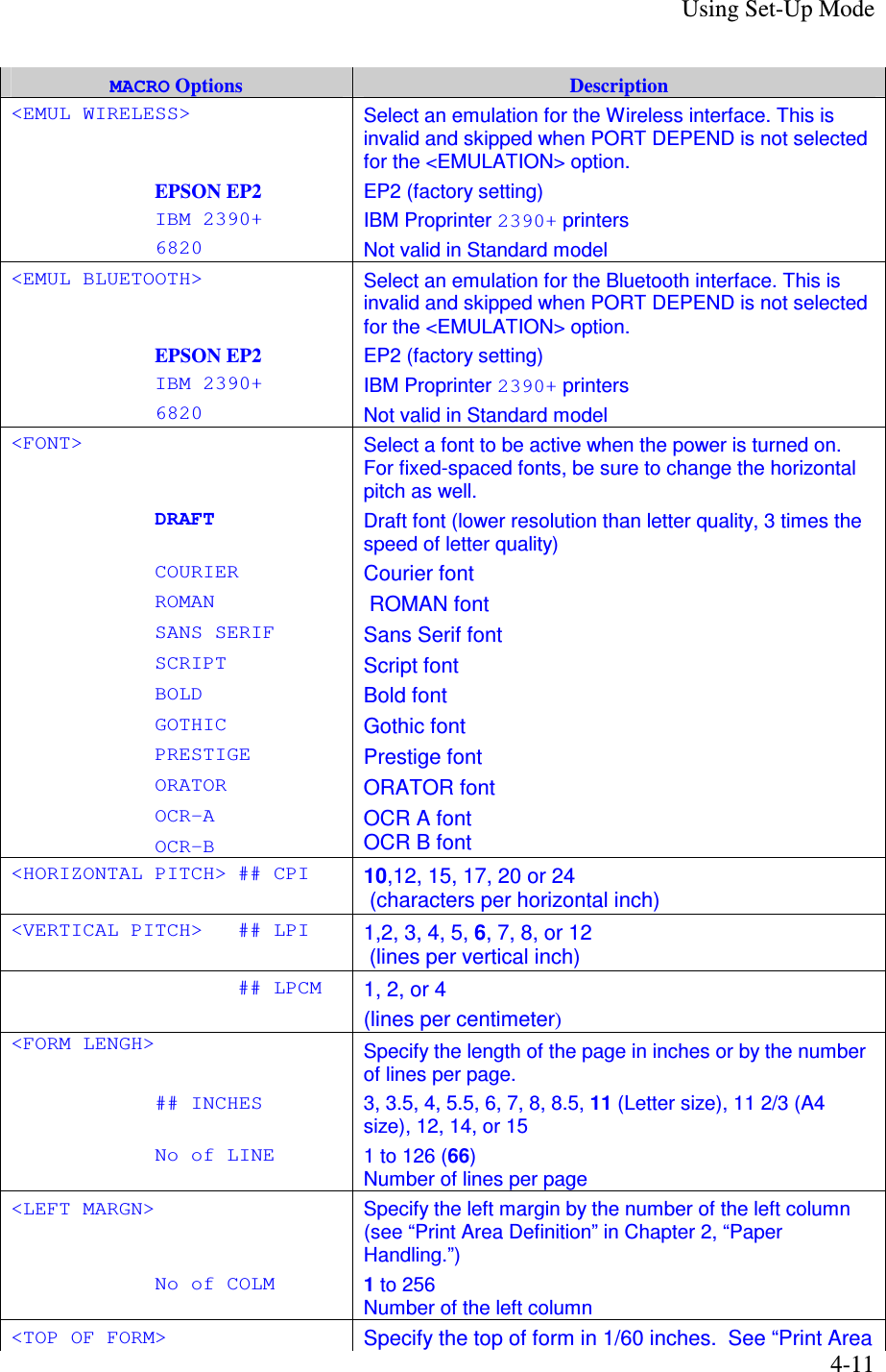
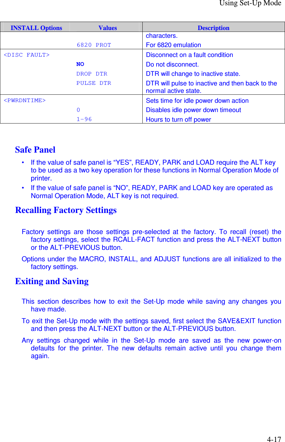
![Using Set-Up Mode 4-21 Hex Dump Mode The Hex Dump mode prints data and commands in hexadecimal characters and abbreviated control codes. The ASCII characters are used for printing. No characters are printed for hexadecimal codes 80 to FF. The Hex Dump mode is useful for checking whether your computer is sending the correct commands to the printer and whether the printer is executing the commands correctly. It is also useful for debugging software programs. 1. To enter the Printing Test mode: 1) Make sure that the tractors are loaded with continuous feedpaper and that the paper select lever is set forward. 2) Turn the printer off. 3) Turn the printer back on while pressing the “READY/CLEAR” + “ALT” buttons. Note: Do not press any buttons alone or in combination except for pressing the READY and ALT buttons alone when turning the printer on, to avoid initiating unexpected tests not permitted for the user. 2. Print the Hex Dump. 1) To start Hex Dump printing, send your file or program to the printer. The printer goes online and prints the Hex Dump. 2) Press the READY button to pause and resume printing in Hex Dump mode. To resume Hex Dump printing, press the READY button again. 3) To print another Hex Dump, send another file to the printer. 3. Exit the Hex Dump mode Turn the printer off to exit the Hex Dump mode. 4. Sample of Hex Dump printing format 0000 00 01 02 03 04 05 . . . . 0C 0D 0E 0F ................ 0010 10 11 12 13 14 15 . . . . 1C 1D 1E 1F ................ 0020 20 21 22 23 24 25 . . . . 2C 2D 2E 2F !"#$%&'()*+,-./ 0030 30 31 32 33 34 35 . . . . 3C 3D 3E 3F 0123456789:;<=>? 0040 40 41 42 43 44 45 . . . . 4C 4D 4E 4F @ABCDEFGHIJKLMNO 0050 50 51 52 53 54 55 . . . . 5C 5D 5E 5F PQRSTUVWXYZ[\]^_ Address Hex data ASCII](https://usermanual.wiki/TOSHIBA-TEC-Singapore/S-0601.Users-Manual-10/User-Guide-650724-Page-21.png)