Strix Systems MWS100NA 802.11 a/g Wireless Networking Device User Manual MWS100 Config A3
Strix Systems, Inc. 802.11 a/g Wireless Networking Device MWS100 Config A3
UserManual.wiki
>
Strix Systems
>
MWS100NA User Manual
>
User Guide
Contents
1.
Quick Starter Guide
2.
User Guide
3.
Quick Start Guide
4.
Users Manual
5.
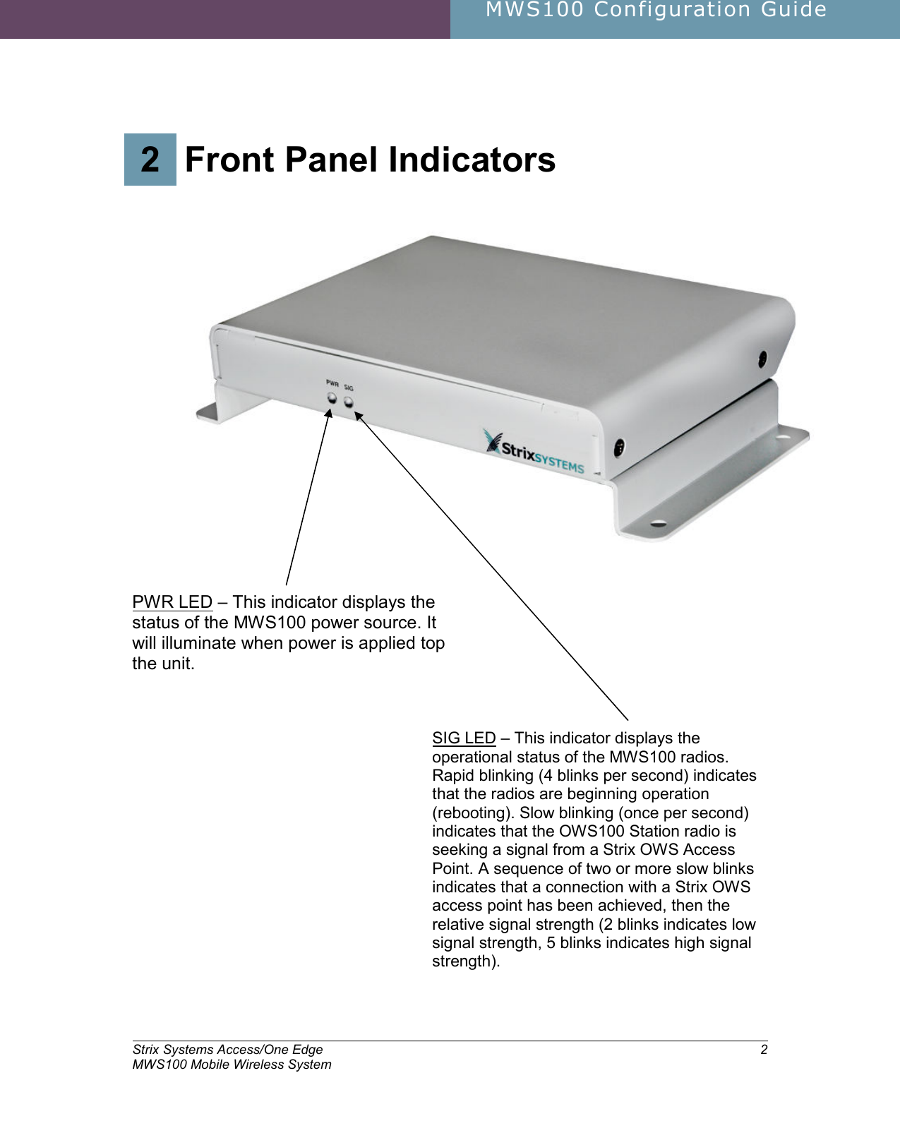
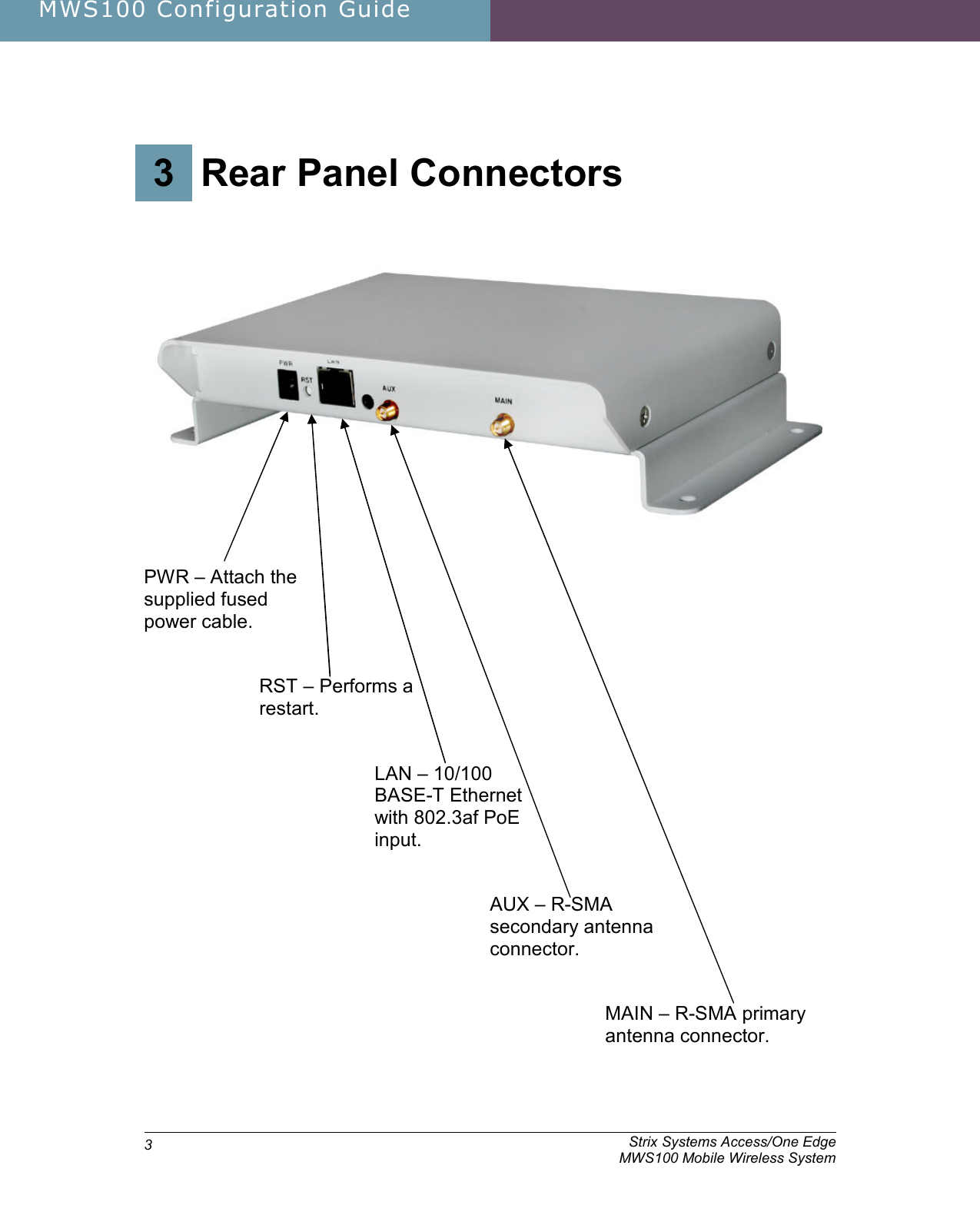
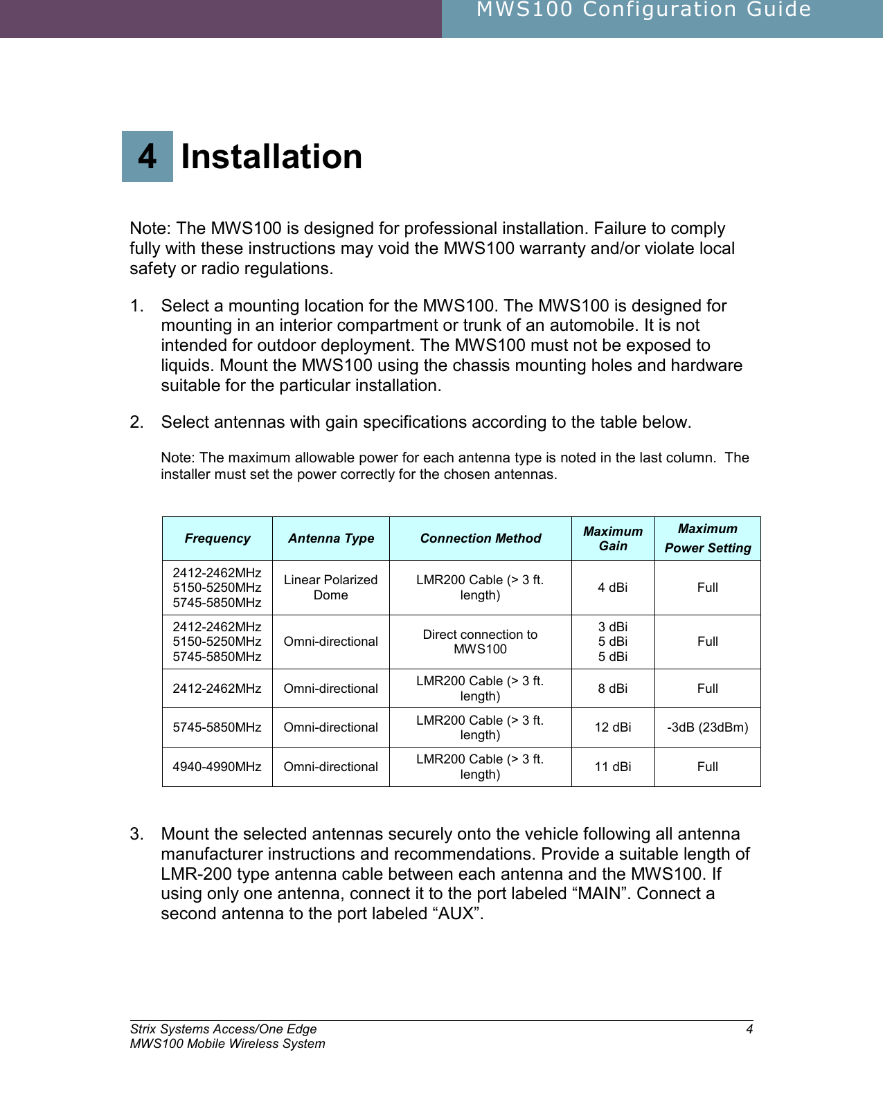
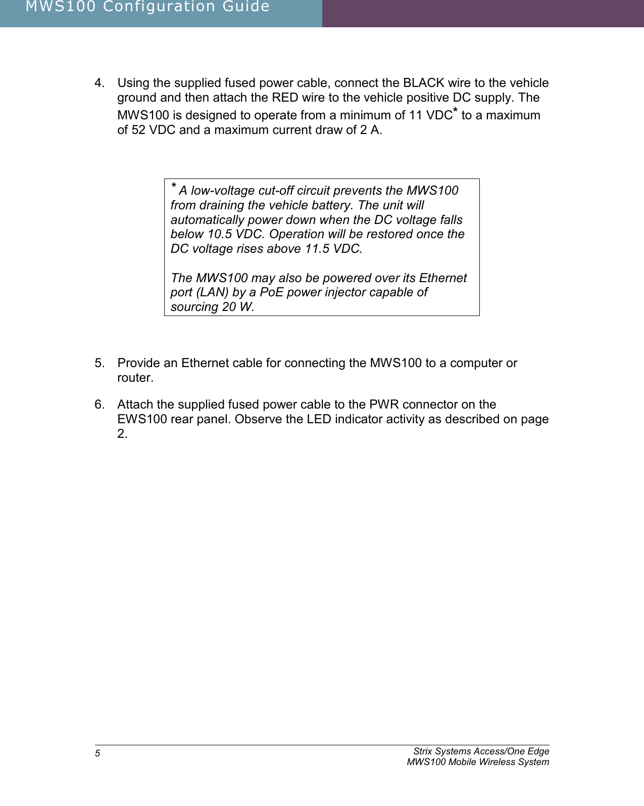
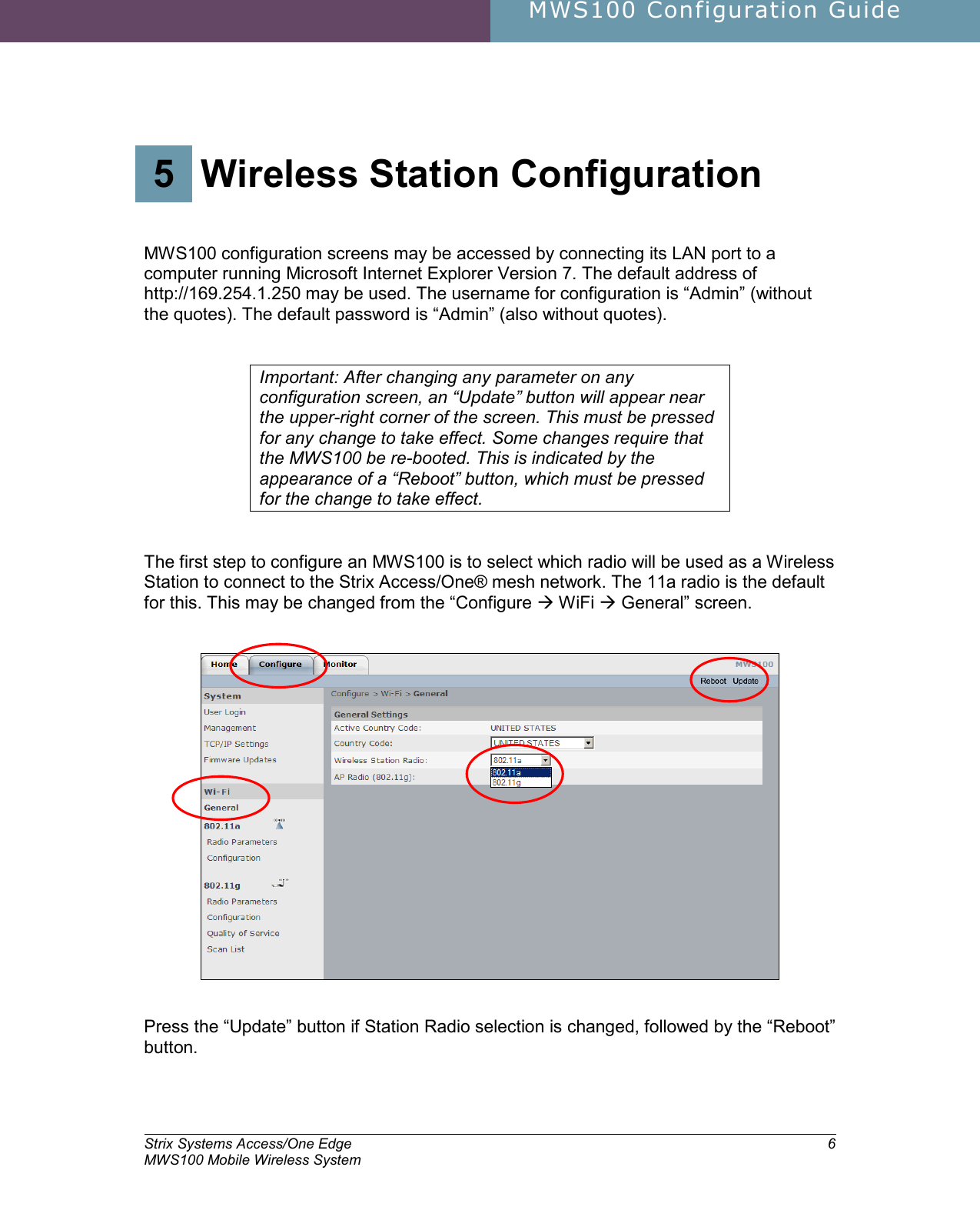
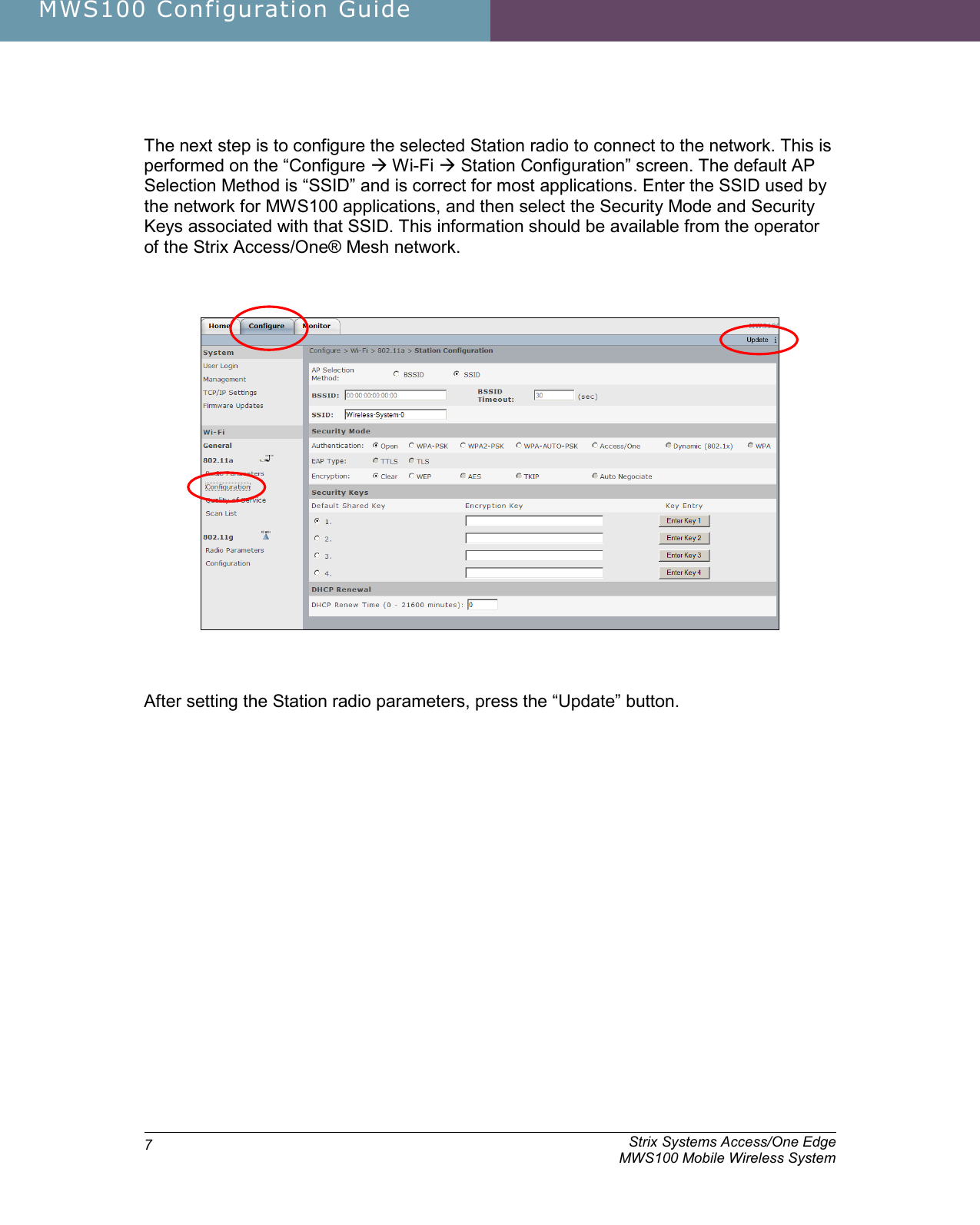
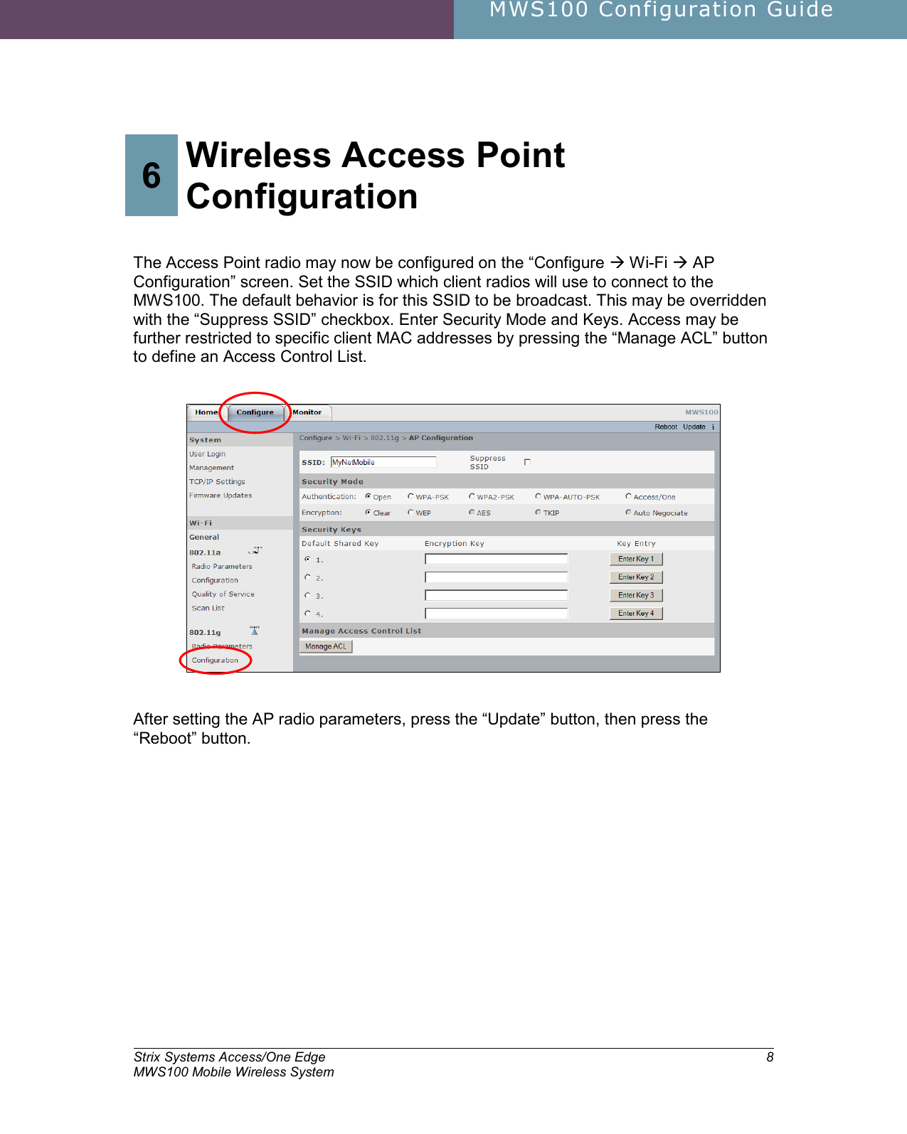
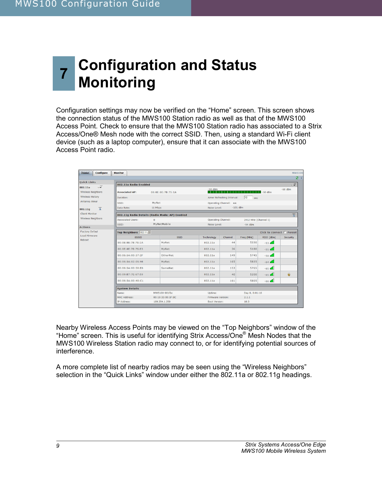
Configuration Guide
User Guide
Navigation menu
Upload a User Manual
Namespaces
Wiki Guide
HTML
PDF
Info
Views
User Manual
Discussion / Help
Navigation