Spectralux 14114 Dlink+ w/CPDLC. All-in-one data communications, CPDLC and ACARS in a single LRU User Manual 2
Spectralux Corporation Dlink+ w/CPDLC. All-in-one data communications, CPDLC and ACARS in a single LRU Users Manual 2
Contents
- 1. Installation Manual
- 2. Users Manual 1
- 3. Users Manual 2
- 4. Users Manual
Users Manual 2
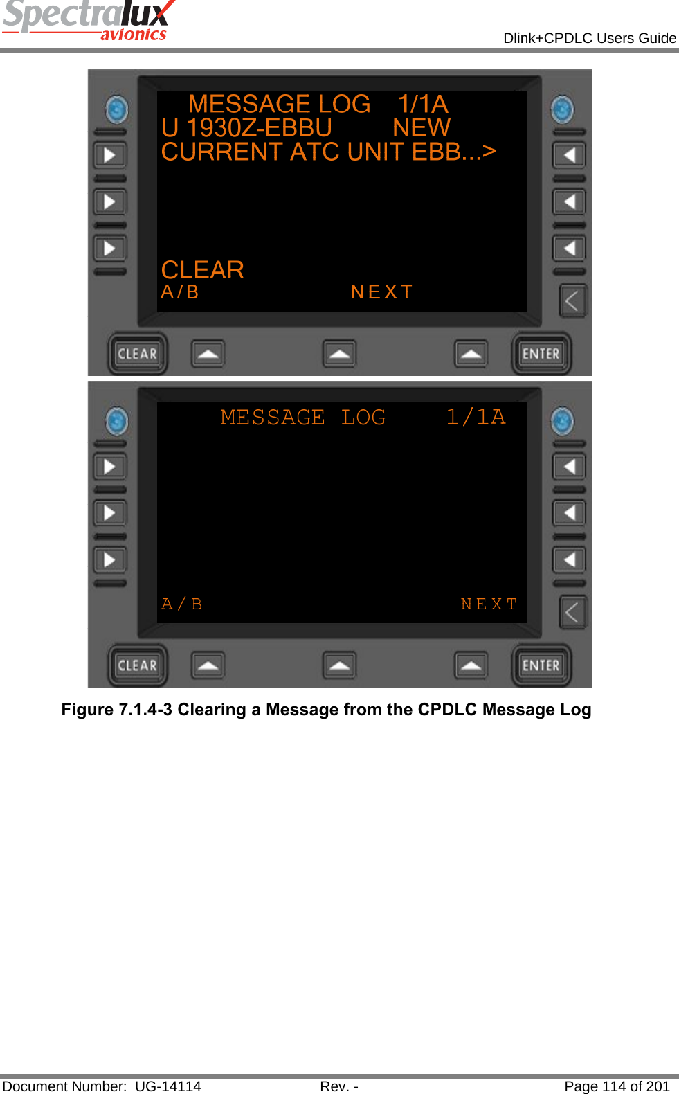
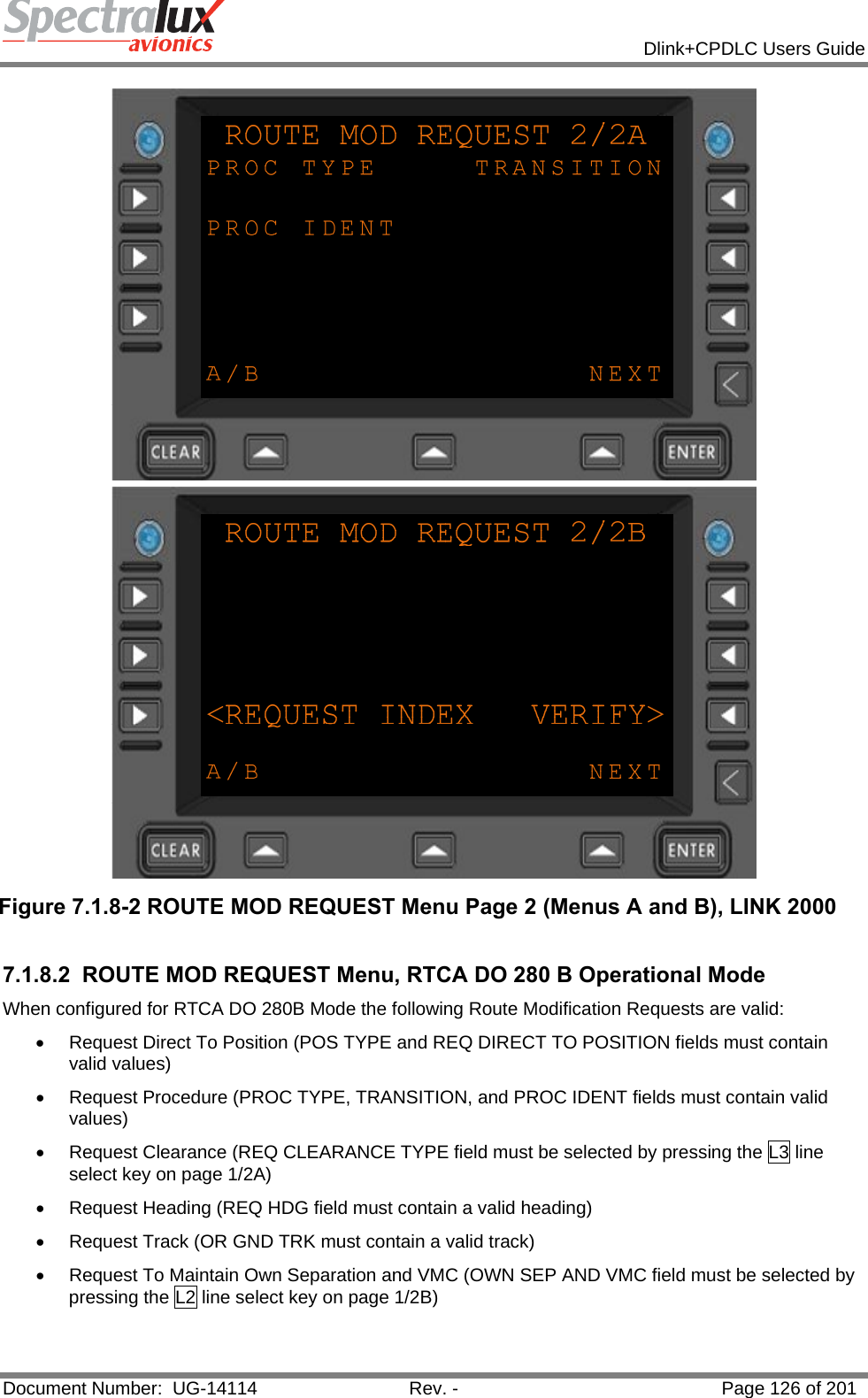
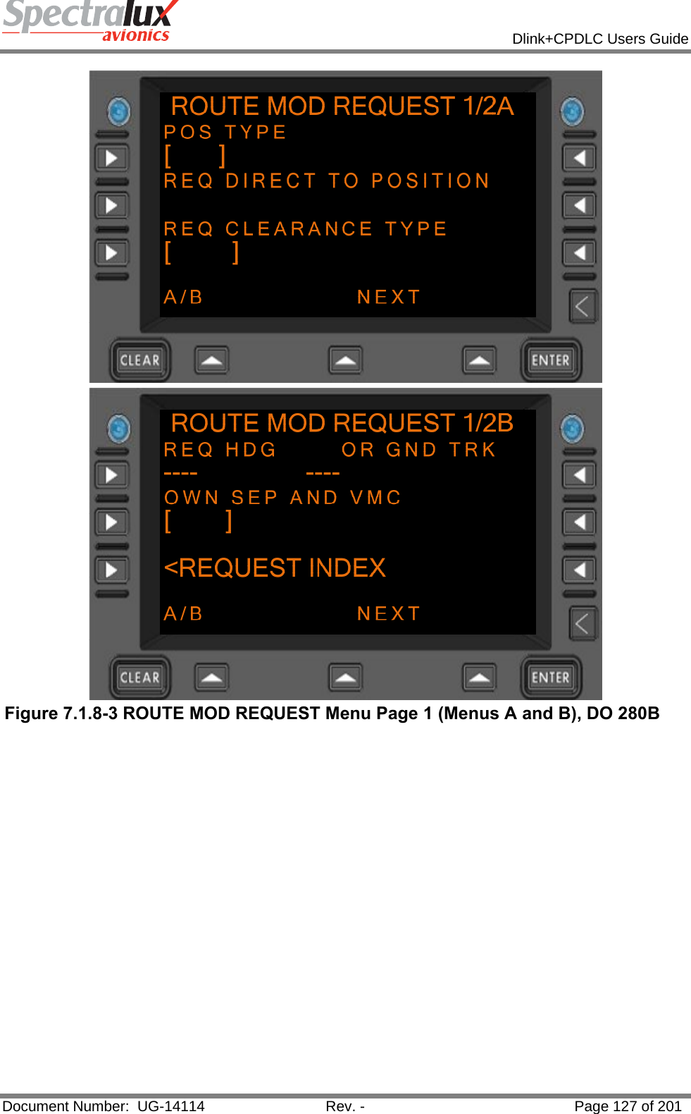
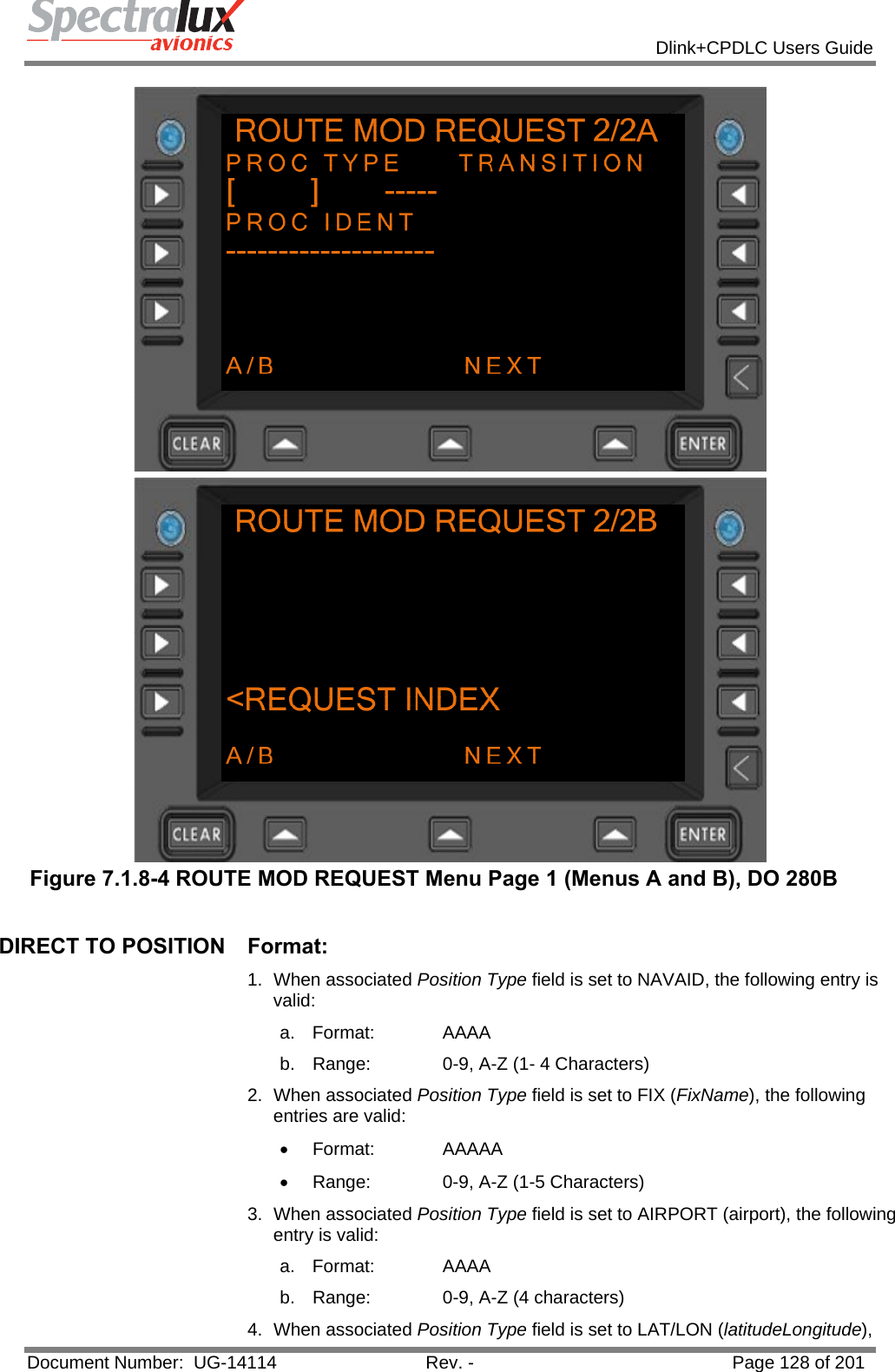
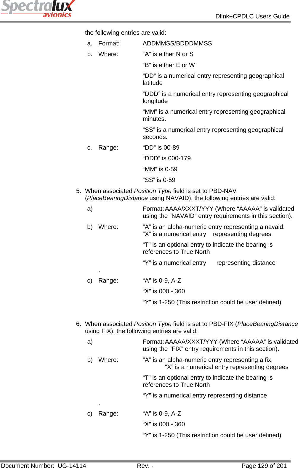
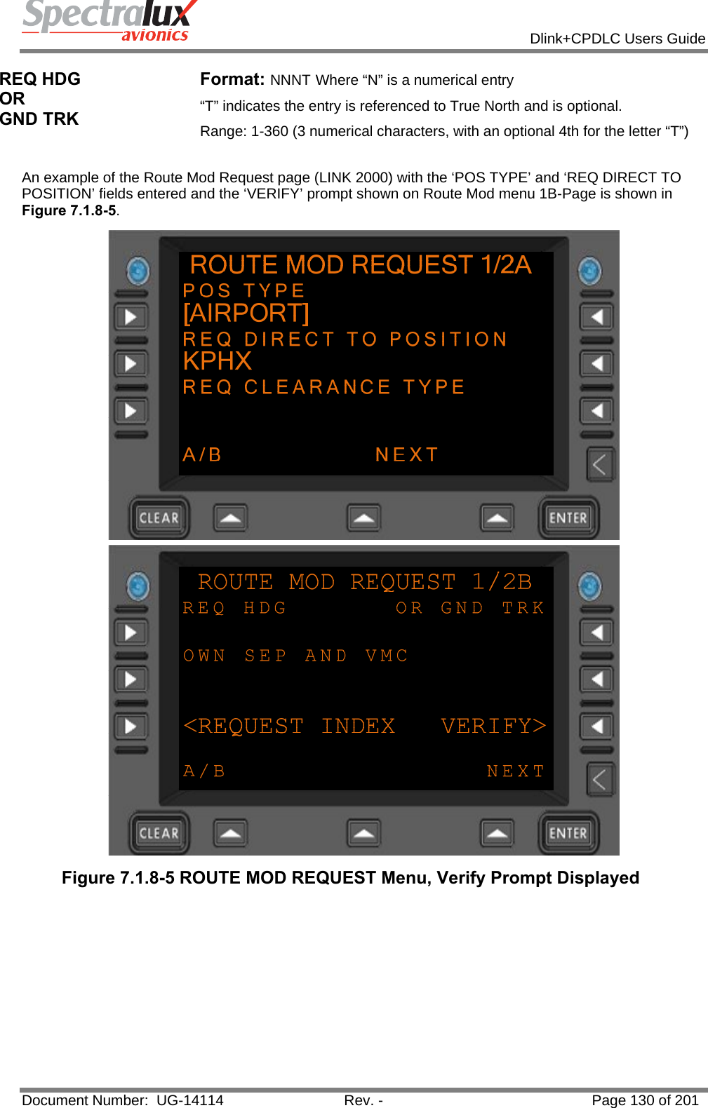
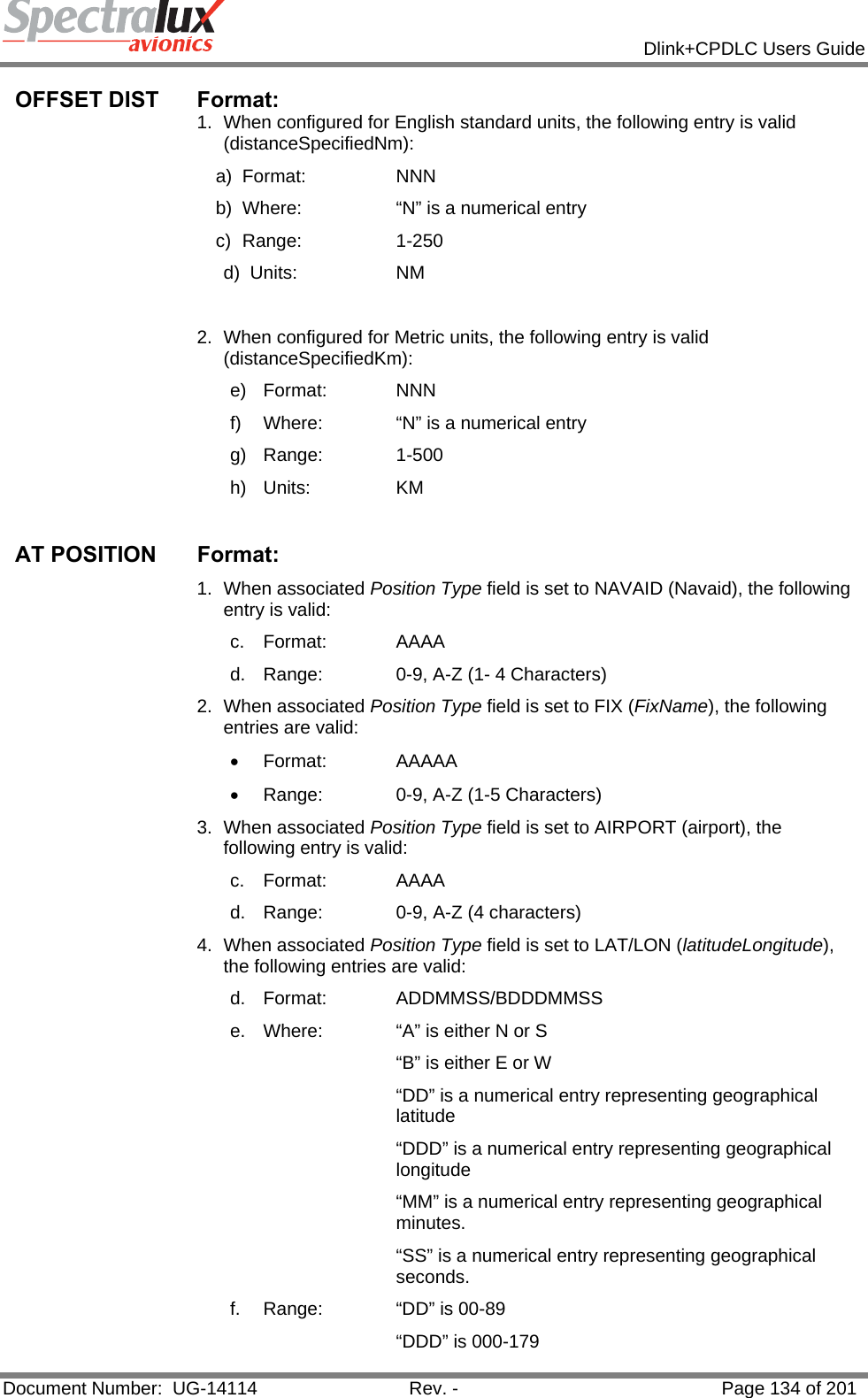
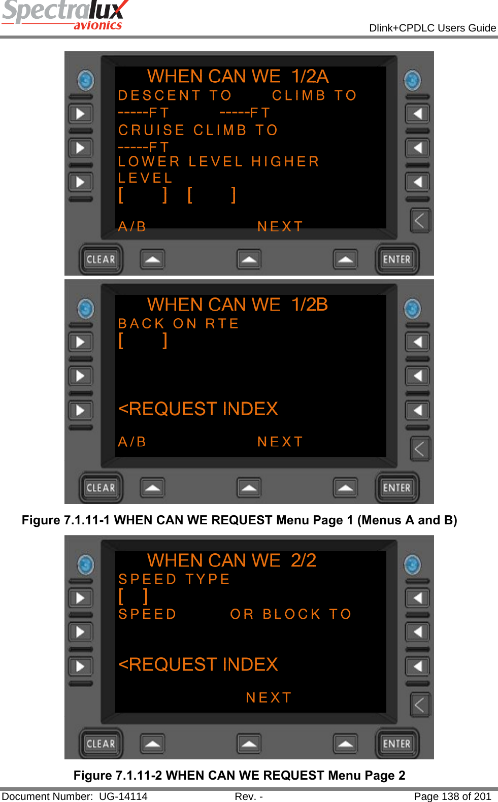
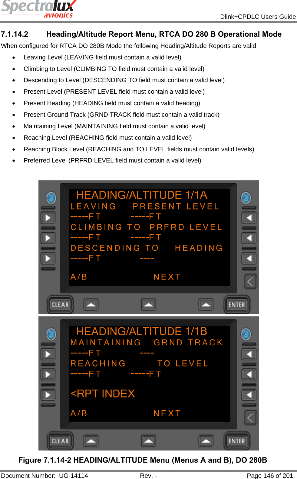
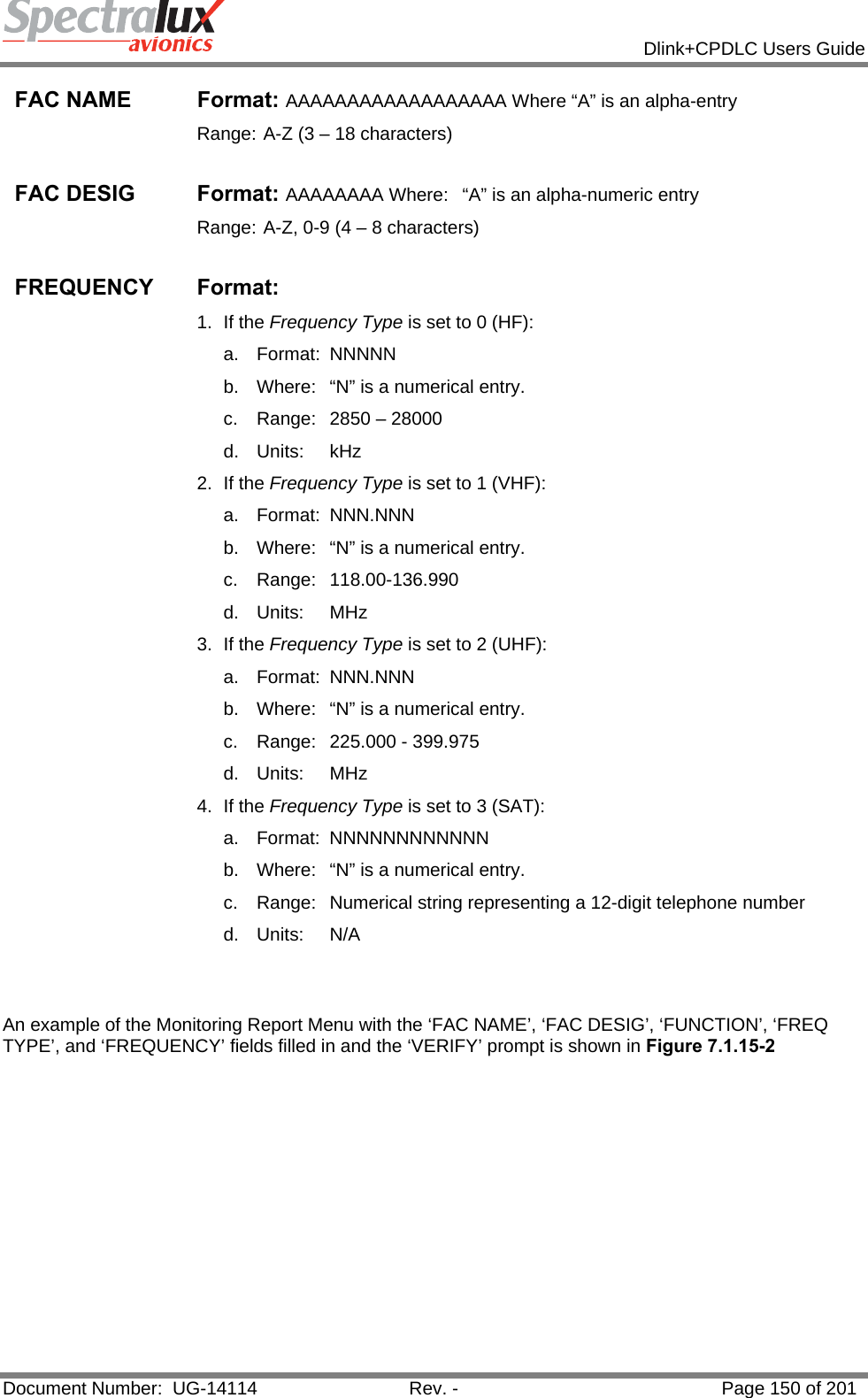
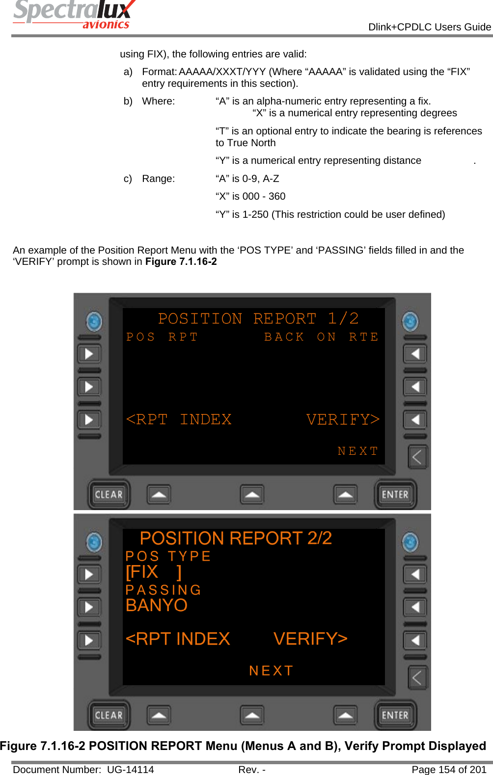
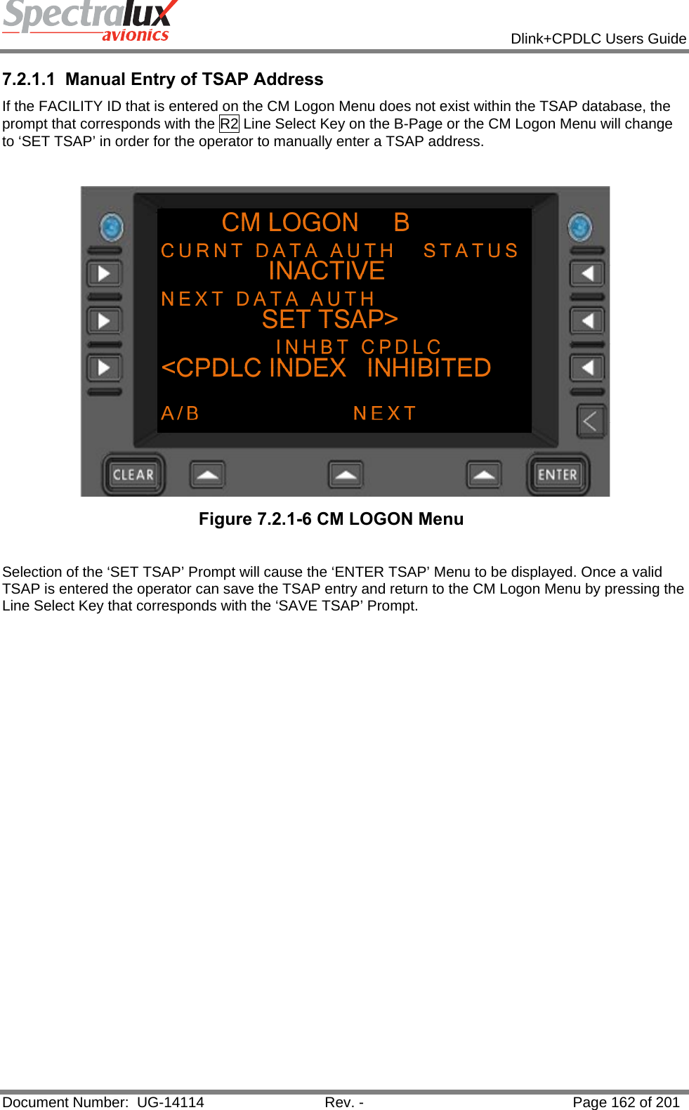
![Dlink+CPDLC Users Guide Document Number: UG-14114 Rev. - Page 180 of 201 7.3 Supported ATN CPDLC Messages 7.3.1 Uplink Messages Supported by Dlink+ w/CPDLC The list below defines those uplink messages supported by Dlink+ w/CPDLC when in RTCA DO280B ATN Operational Mode. When in LINK 2000 ATN Operational Mode, supported uplink messages are limited to those messages that are shaded in yellow. (See Section7.1.1 for information on how the ATN Operational Mode can be changed.) Uplink Message Element Message Element Format Message Intent 0 UNABLE UNABLE - Indicates that ATC cannot comply with the request. 1 STANDBY STANDBY - Indicates that ATC has received the message and will respond. 2 REQUEST DEFERRED REQUEST DEFERRED - Indicates that ATC has received the request but it has been deferred until later. 3 ROGER ROGER - Indicates that ATC has received and understood the message. 4 AFFIRM AFFIRM - Yes. 5 NEGATIVE NEGATIVE - No. 6 EXPECT 25000FT EXPECT [level] - Notification that a level change instruction should be expected. 7 EXPECT CLIMB AT 1232 EXPECT CLIMB AT [time] - Notification that an instruction should be expected for the aircraft to commence climb at the specified time. 8 EXPECT CLIMB AT KXX EXPECT CLIMB AT [position] - Notification that an instruction should be expected for the aircraft to commence climb at the specified position. 9 EXPECT DESCENT AT 1232 EXPECT DESCENT AT [time] - Notification that an instruction should be expected for the aircraft to commence descent at the specified time. 10 EXPECT DESCENT AT XXZ EXPECT DESCENT AT [position] - Notification that an instruction should be expected for the aircraft to commence descent at the specified position. 11 EXPECT CRUISE CLIMB AT 1232 EXPECT CRUISE CLIMB AT [time] - Notification that an instruction should be expected for the aircraft to commence cruise climb at the specified time. 12 EXPECT CRUISE CLIMB AT XYZ EXPECT CRUISE CLIMB AT [position] -Notification that an instruction should be expected for the aircraft to commence cruise climb at the specified position. 13 AT 1232 EXPECT CLIMB TO 25000FT AT [time] EXPECT CLIMB TO [level] - Notification that an instruction should be expected for the aircraft to commence climb at the specified time to the specified level. 14 AT XYZ EXPECT CLIMB TO 25000FT AT [position] EXPECT CLIMB TO [level] - Notification that an instruction should be expected for the aircraft to commence climb at the specified position to the specified level. 15 AT 1232 EXPECT DESCENT TO 25000FT AT [time] EXPECT DESCENT TO [level] -Notification that an instruction should be expected for the aircraft to commence descent at the specified time to the specified level.](https://usermanual.wiki/Spectralux/14114.Users-Manual-2/User-Guide-1874938-Page-78.png)
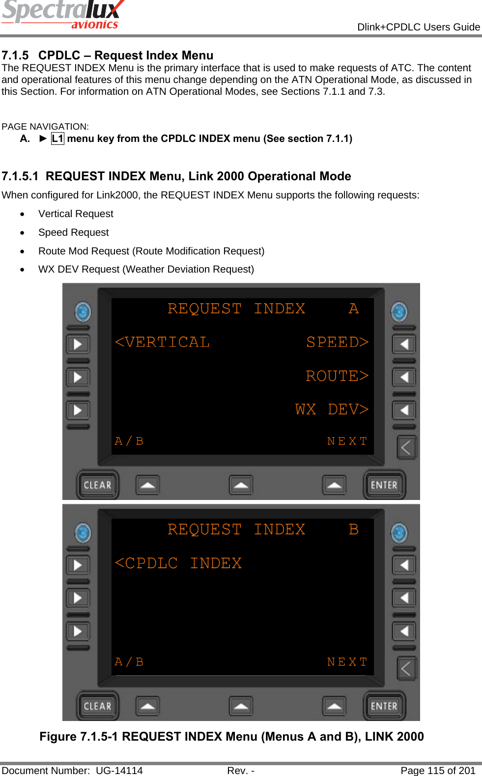
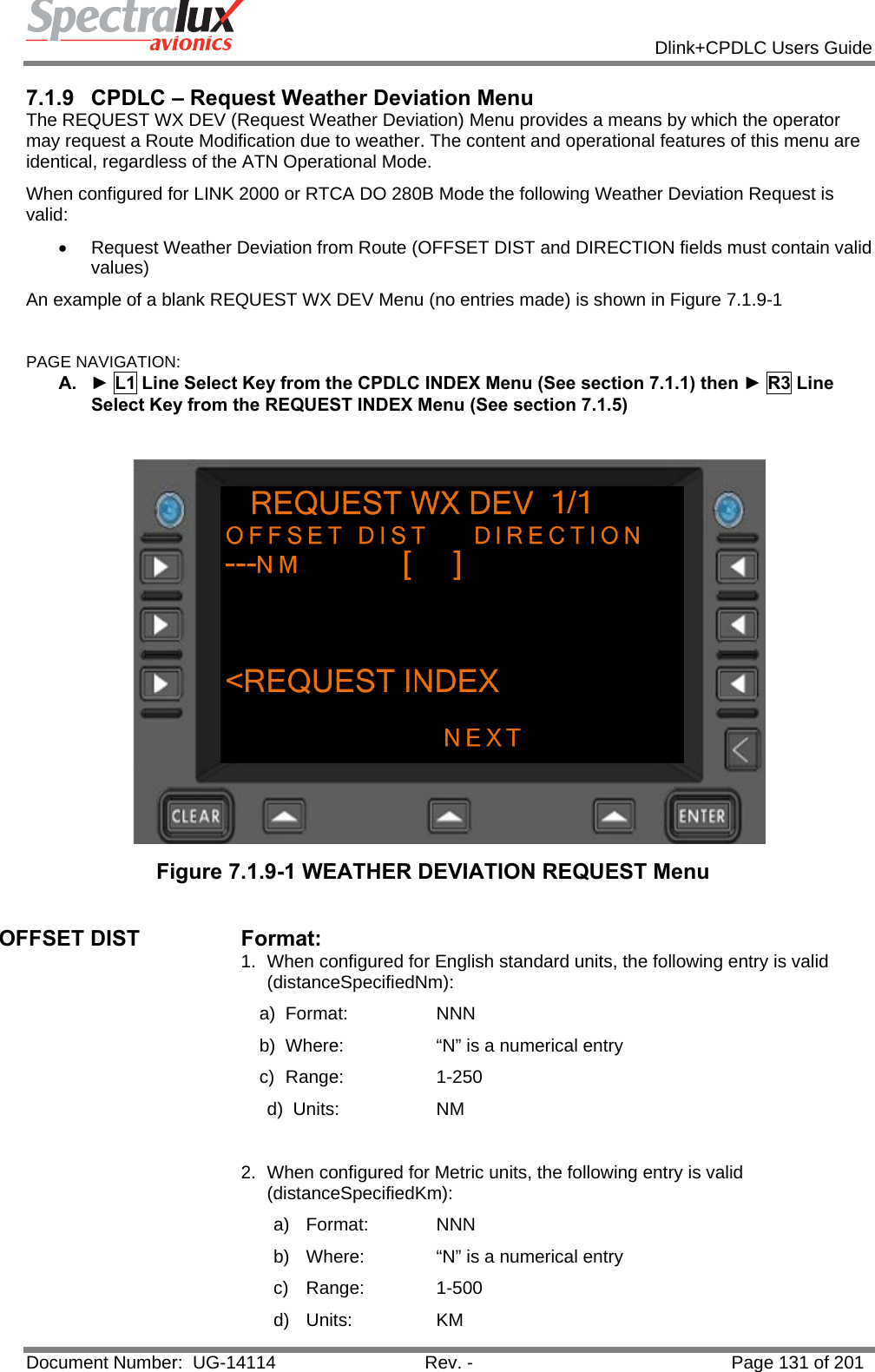
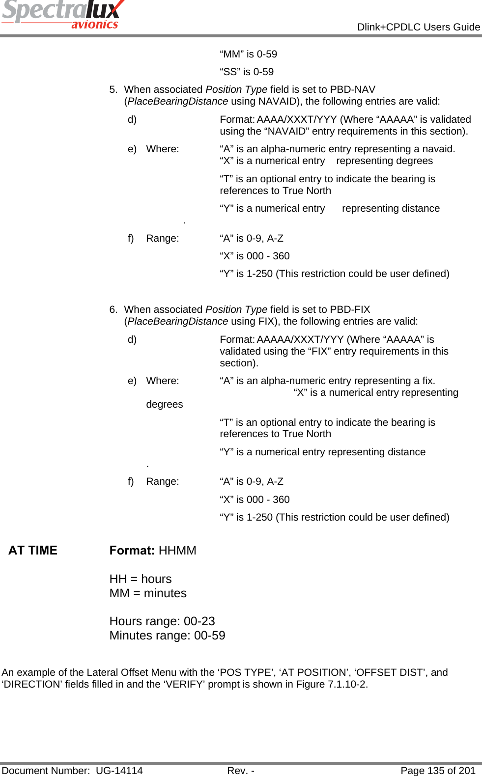
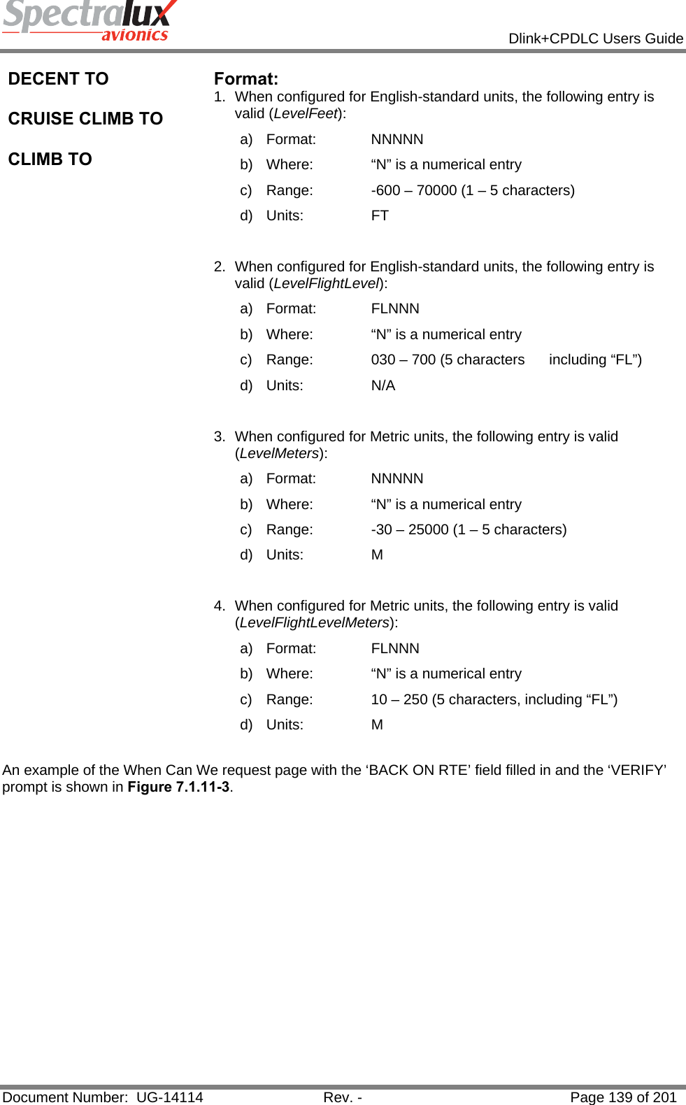
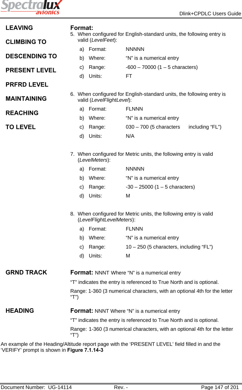
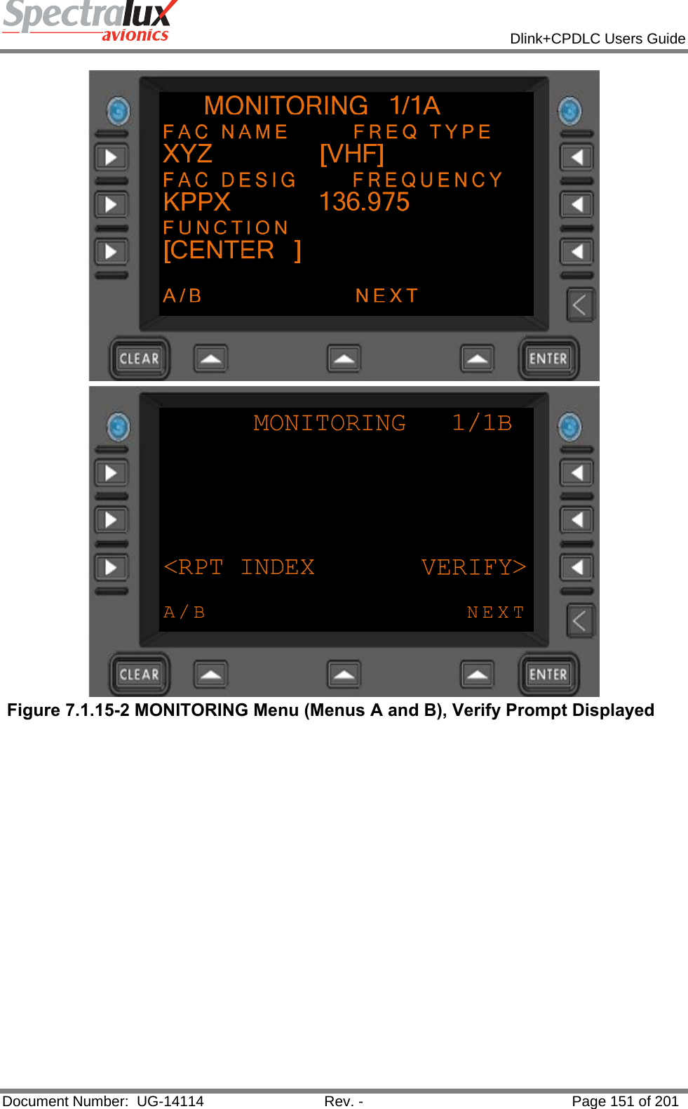
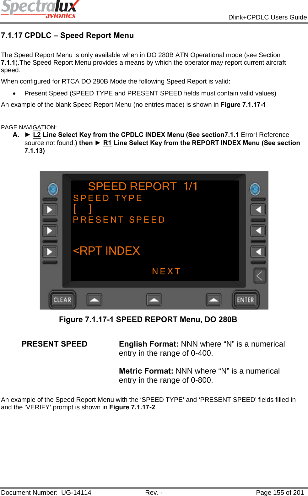
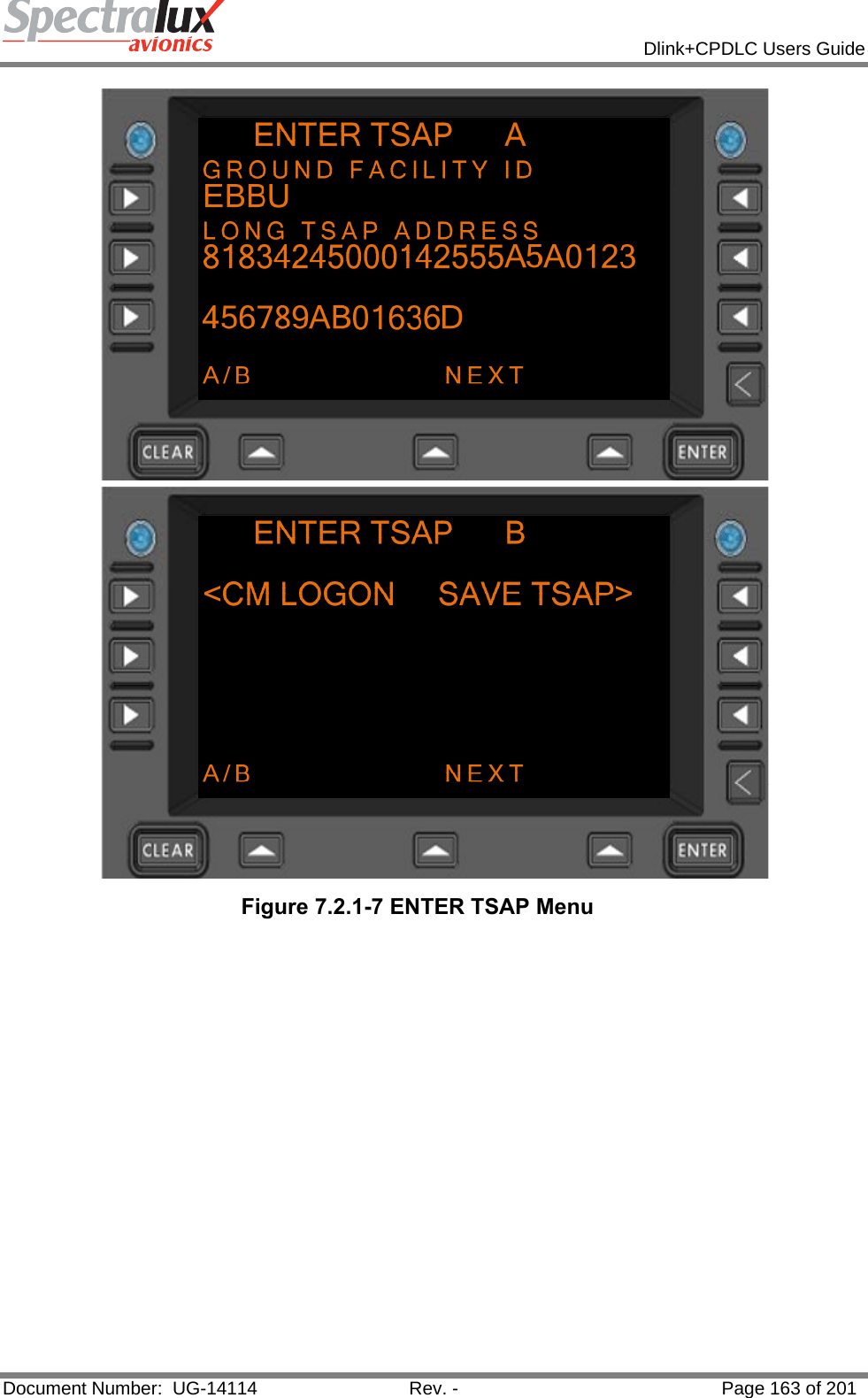
![Dlink+CPDLC Users Guide Document Number: UG-14114 Rev. - Page 181 of 201 Uplink Message Element Message Element Format Message Intent 16 AT XYZ EXPECT DESCENT TO 25000FT AT [position] EXPECT DESCENT TO [level] -Notification that an instruction should be expected for the aircraft to commence descent at the specified position to the specified level. 17 AT 1232 EXPECT CRUISE CLIMB TO 25000FT AT [time] EXPECT CRUISE CLIMB TO [level] -Notification that an instruction should be expected for the aircraft to commence cruise climb at the specified time to the specified level. 18 AT XYZ EXPECT CRUISE CLIMBE TO 25000FT AT [position] EXPECT CRUISE CLIMBE TO [level] -Notification that an instruction should be expected for the aircraft to commence cruise climb at the specified position to the specified level. 19 MAINTAIN 25000FT MAINTAIN [level] - Instruction to maintain the specified level. 20 CLIMB TO 25000FT CLIMB TO [level] - Instruction that a climb to a specified level is to commence and once reached the specified level is to be maintained. 21 AT 1232 CLIMB TO 25000FT AT [time] CLIMB TO [level] - Instruction that at the specified time a climb to the specified level is to commence and once reached the specified level is to be maintained. 22 AT XYZ CLIMB TO 25000FT AT [position] CLIMB TO [level] - Instruction that at the specified position a climb to the specified level is to commence and once reached the specified level is to be maintained. 23 DESCEND TO 25000FT DESCEND TO [level] - Instruction that a descent to a specified level is to commence and once reached the specified level is to be maintained. 24 AT 1232 DESCEND TO 25000FT AT [time] DESCEND TO [level] - Instruction that at a specified time a descent to a specified level is to commence and once reached the specified level is to be maintained. 25 AT XYZ DESCEND TO 25000FT AT [position] DESCEND TO [level] - Instruction that at the specified position a descent to the specified level is to commence and once reached the specified level is to be maintained. 26 CLIMB TO REACH [level] BY 1232 CLIMB TO REACH [level] BY [time] - Instruction that a climb is to commence at a rate such that the specified level is reached at or before the specified time. 27 CLIMB TO REACH 25000FT BY XYZ CLIMB TO REACH [level] BY [postion] -Instruction that a climb is to commence at a rate such that the specified level is reached at or before the specified position. 28 DESCEND TO REACH 25000FT BY 1232 DESCEND TO REACH [level] BY [time] -Instruction that a descent is to commence at a rate such that the specified level is reached at or before the specified time. 29 DESCEND TO REACH 25000FT BY XYZ DESCEND TO REACH [level] BY [position] -Instruction that a descent is to commence at a rate such that the specified level is reached at or before the specified position. 30 MAINTAIN BLOCK 25000FT TO 25000FT MAINTAIN BLOCK [level] TO [level] - Instruction that a level within the defined vertical range specified is to be maintained. 31 CLIMB TO AND MAINTAIN BLOCK 25000FT TO 30000FT CLIMB TO AND MAINTAIN BLOCK [level] TO [level] - Instruction that a climb to a level within the vertical range](https://usermanual.wiki/Spectralux/14114.Users-Manual-2/User-Guide-1874938-Page-79.png)
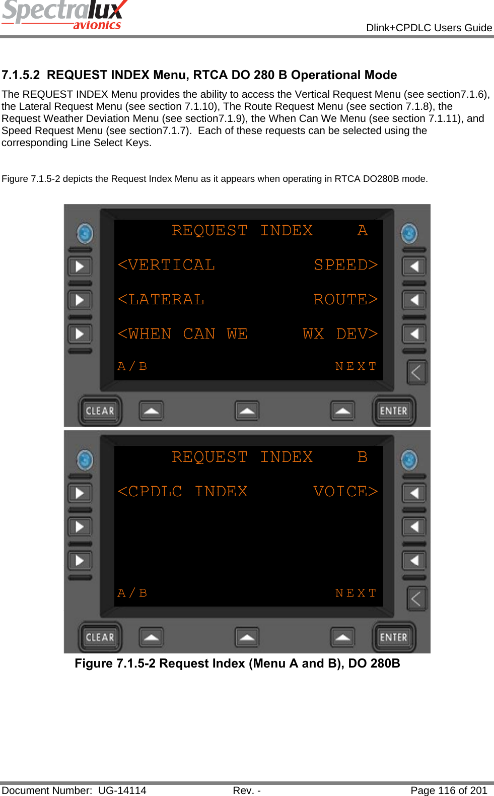
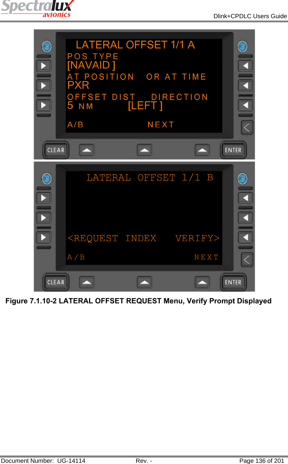
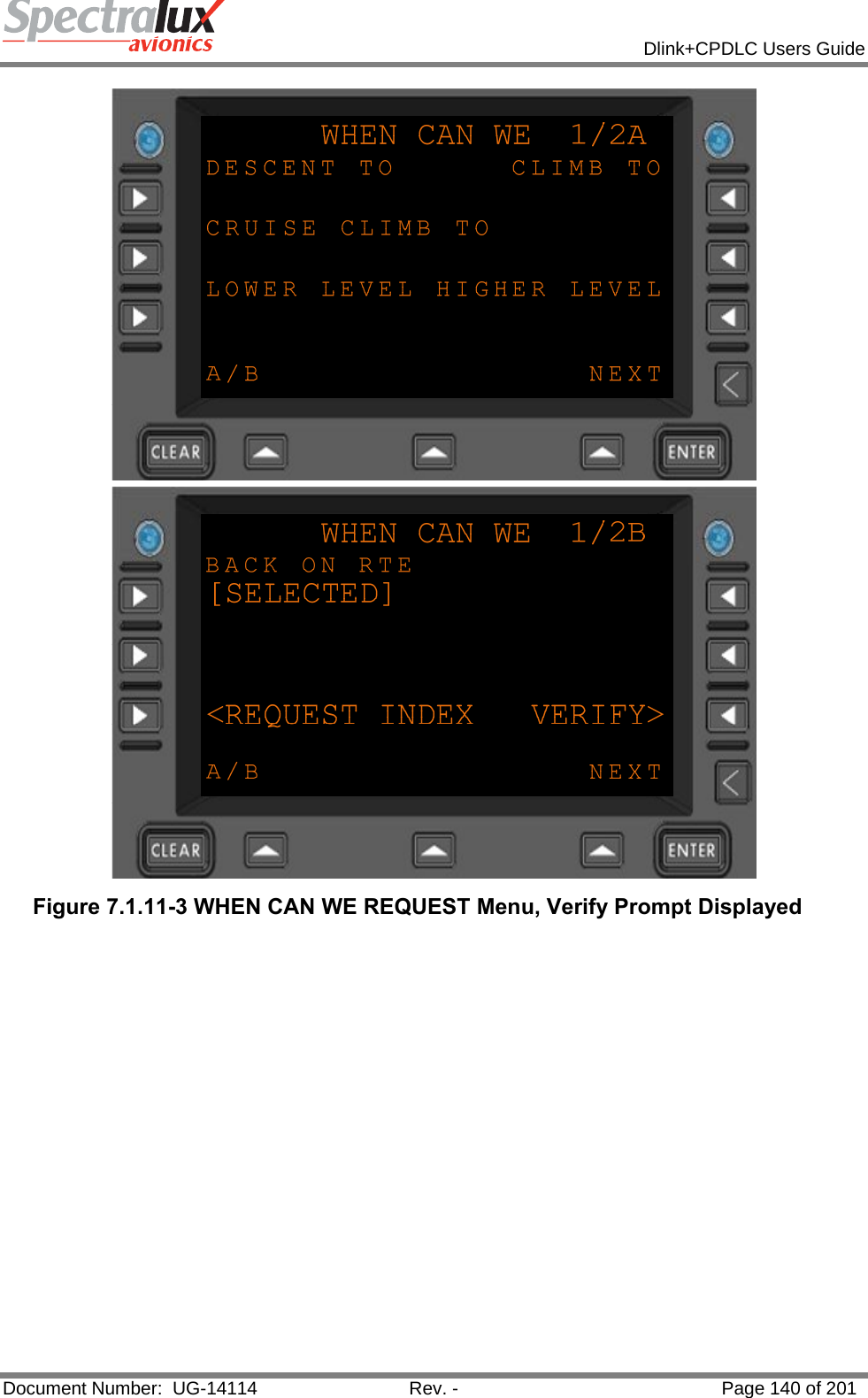
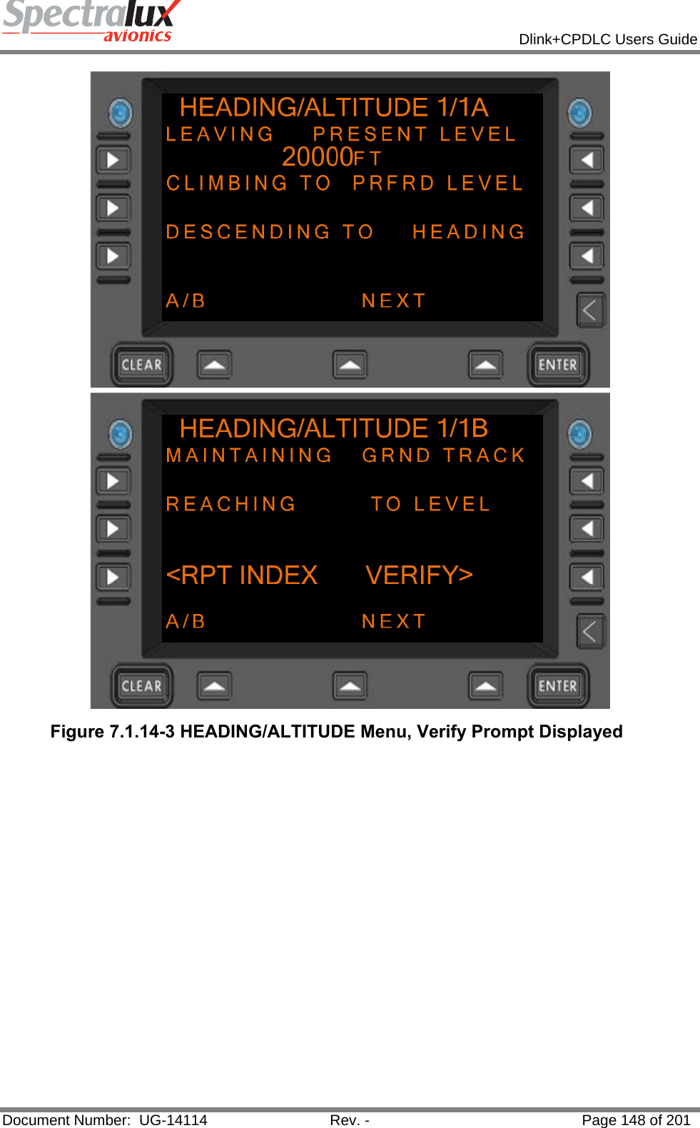
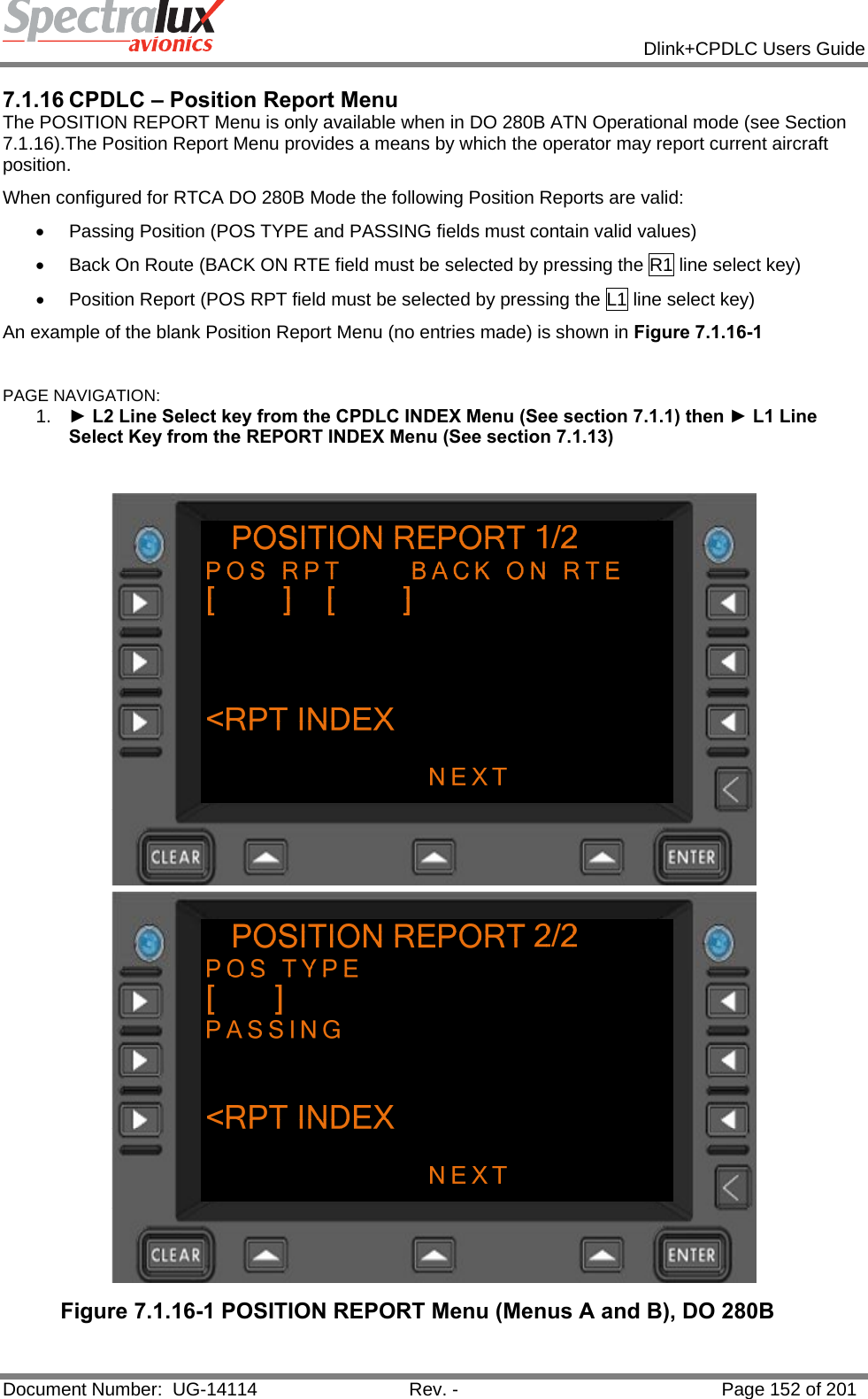
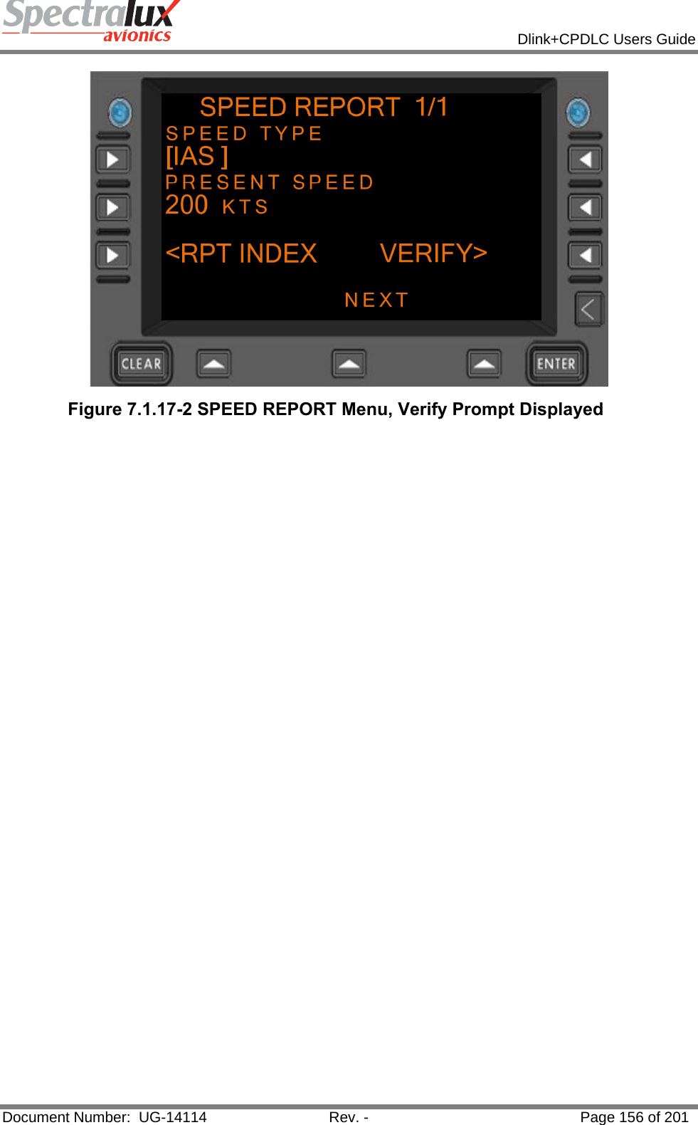
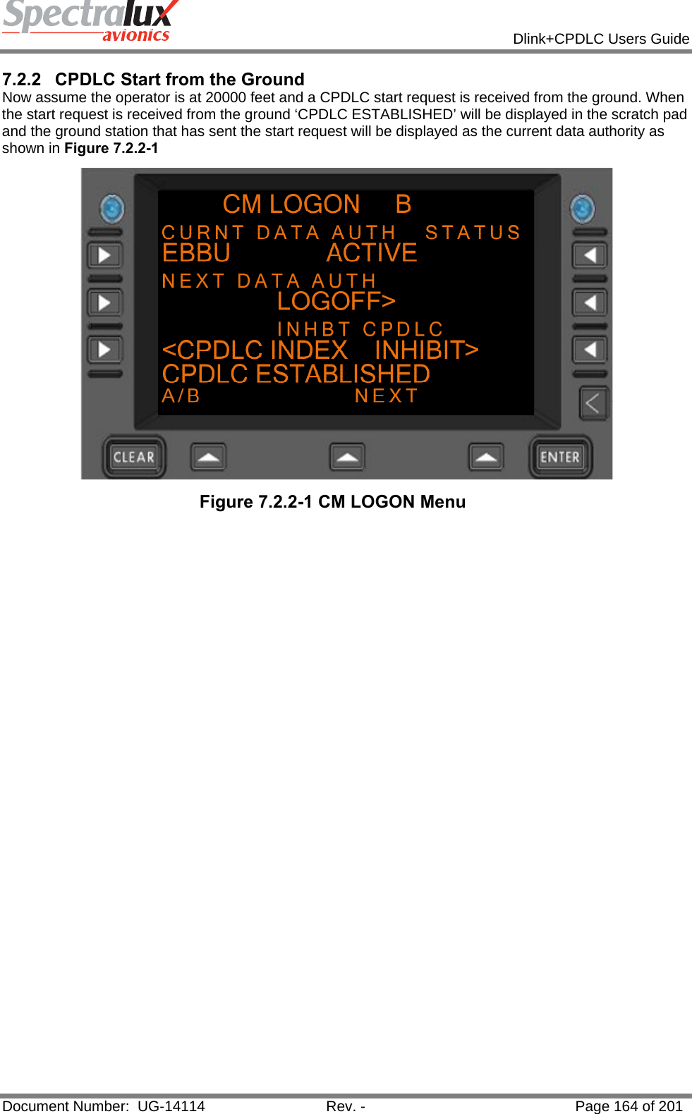
![Dlink+CPDLC Users Guide Document Number: UG-14114 Rev. - Page 182 of 201 Uplink Message Element Message Element Format Message Intent defined is to commence. 32 DESCEND TO AND MAINTAIN BLOCK 25000FT TO 20000FT DESCEND TO AND MAINTAIN BLOCK [level] TO [level] - Instruction that a descent to a level within the vertical range defined is to commence. 34 CRUISE CLIMB TO 25000FT CRUISE CLIMB TO [level] - Instruction that a cruise climb is to commence and continue until the specified level is reached. 35 CRUISE CLIMB TO 25000FT CRUISE CLIMB ABOVE [level] - Instruction that a cruise climb can commence once above the specified level. 36 EXPEDITE CLIMB TO 25000FT EXPEDITE CLIMB TO [level] - Instruction that the climb to the specified level should be made at the aircraft’s best rate. 37 EXPEDITE DESCENT TO 25000FT EXPEDITE DESCENT TO [level] - Instruction that the descent to the specified level should be made at the aircraft’s best rate. 38 IMMEDIATELY CLIMB TO 25000FT IMMEDIATELY CLIMB TO [level] – Urgent instruction to immediately climb to the specified level. 39 IMMEDIATELY DESCEND TO 25000FT IMMEDIATELY DESCEND TO [level] – Urgent instruction to immediately descend to the specified level. 42 EXPECT TO CROSS XYZ AT 25000FT EXPECT TO CROSS [position] AT [level] -Notification that a level change instruction should be expected which will require the specified position to be crossed at the specified level. 43 EXPECT TO CROSS XYZ AT OR ABOVE 25000FT EXPECT TO CROSS [position] AT OR ABOVE [level] - Notification that a level change instruction should be expected which will require the specified position to be crossed at or above the specified level. 44 EXPECT TO CROSS XYZ AT OR BELOW 25000FT EXPECT TO CROSS [position] AT OR BELOW [level] - Notification that a level change instruction should be expected which will require the specified position to be crossed at or below the specified level. 45 EXPECT TO CROSS XYZ AT AND MAINTAIN 25000FT EXPECT TO CROSS [position] AT AND MAINTAIN [level] - Notification that a level change instruction should be expected which will require the specified position to be crossed at the specified level which is to be maintained subsequently. 46 CROSS XYZ AT 25000FT CROSS [position] AT [level] - Instruction that the specified position is to be crossed at the specified level. This may require the aircraft to modify its climb or descent profile. 47 CROSS XYZ AT OR ABOVE 25000FT CROSS [position] AT OR ABOVE [level] -Instruction that the specified position is to be crossed at or above the specified level. 48 CROSS XYZ AT OR ABOVE 25000FT CROSS [position] AT OR BELOW [level] - Instruction that the specified position is to be crossed at or below the specified level. 49 CROSS XYZ AT AND MAINTAIN 25000FT CROSS [position] AT AND MAINTAIN [level] -Instruction that the specified position is to be crossed at the specified level and that level is to be maintained when reached. 50 CROSS XYZ BETWEEN 20000FT AND 25000FT CROSS [position] BETWEEN [level] AND [level] -Instruction that the specified position is to be crossed at a level between the specified levels.](https://usermanual.wiki/Spectralux/14114.Users-Manual-2/User-Guide-1874938-Page-80.png)
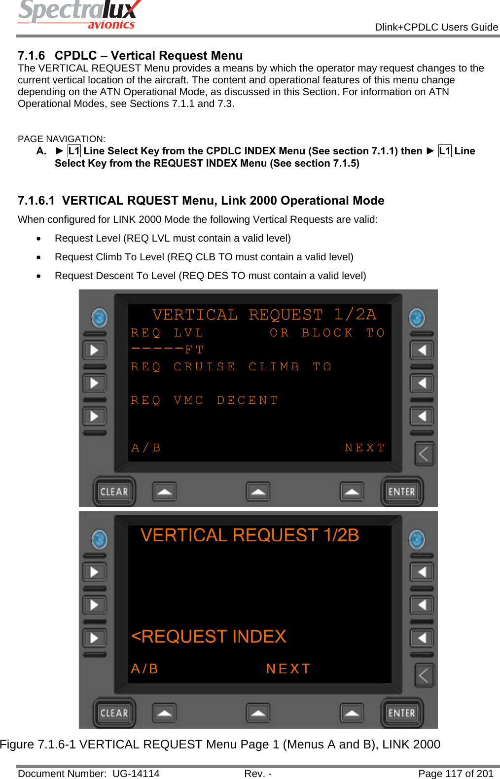
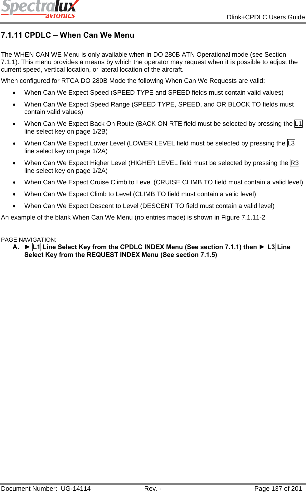
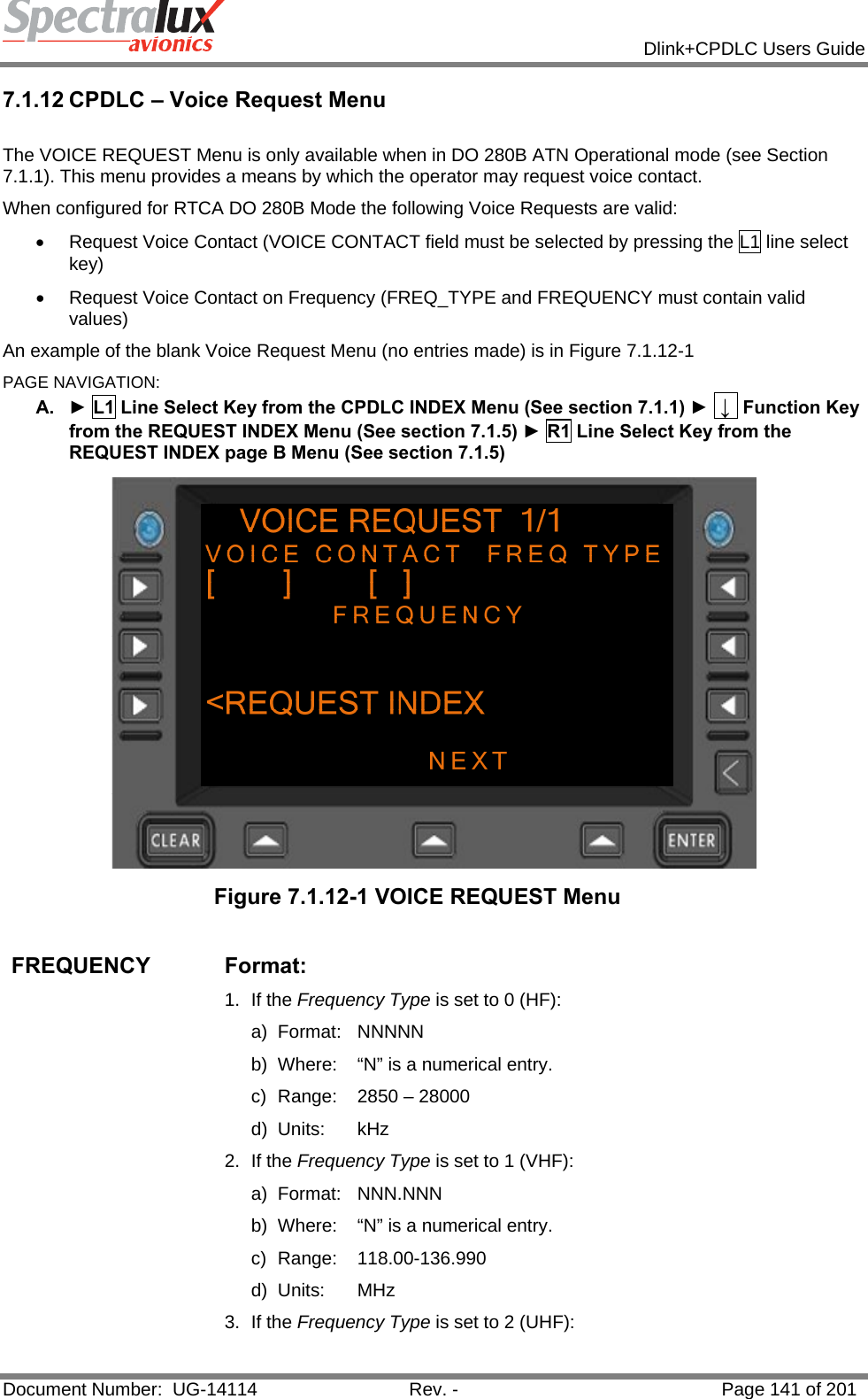
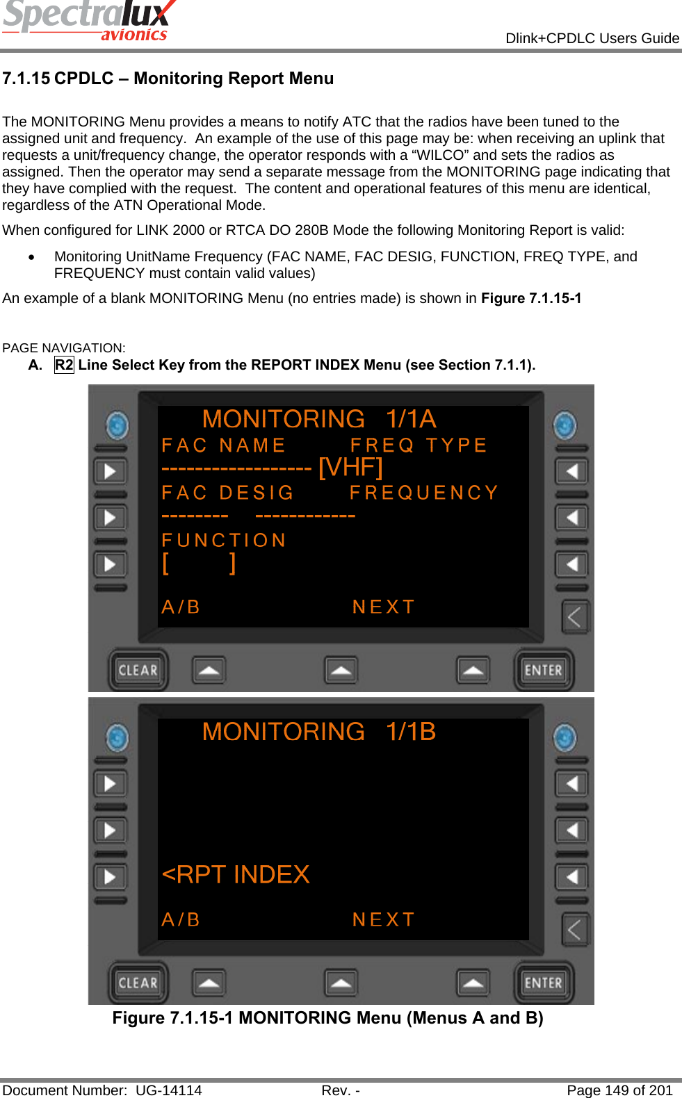
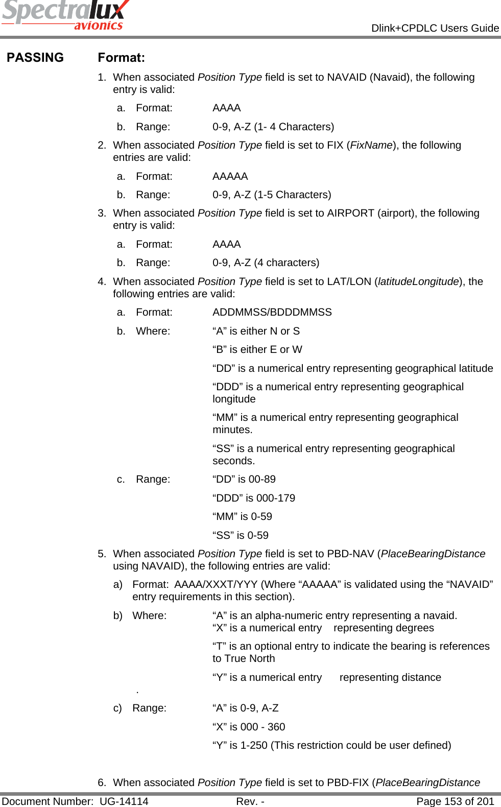
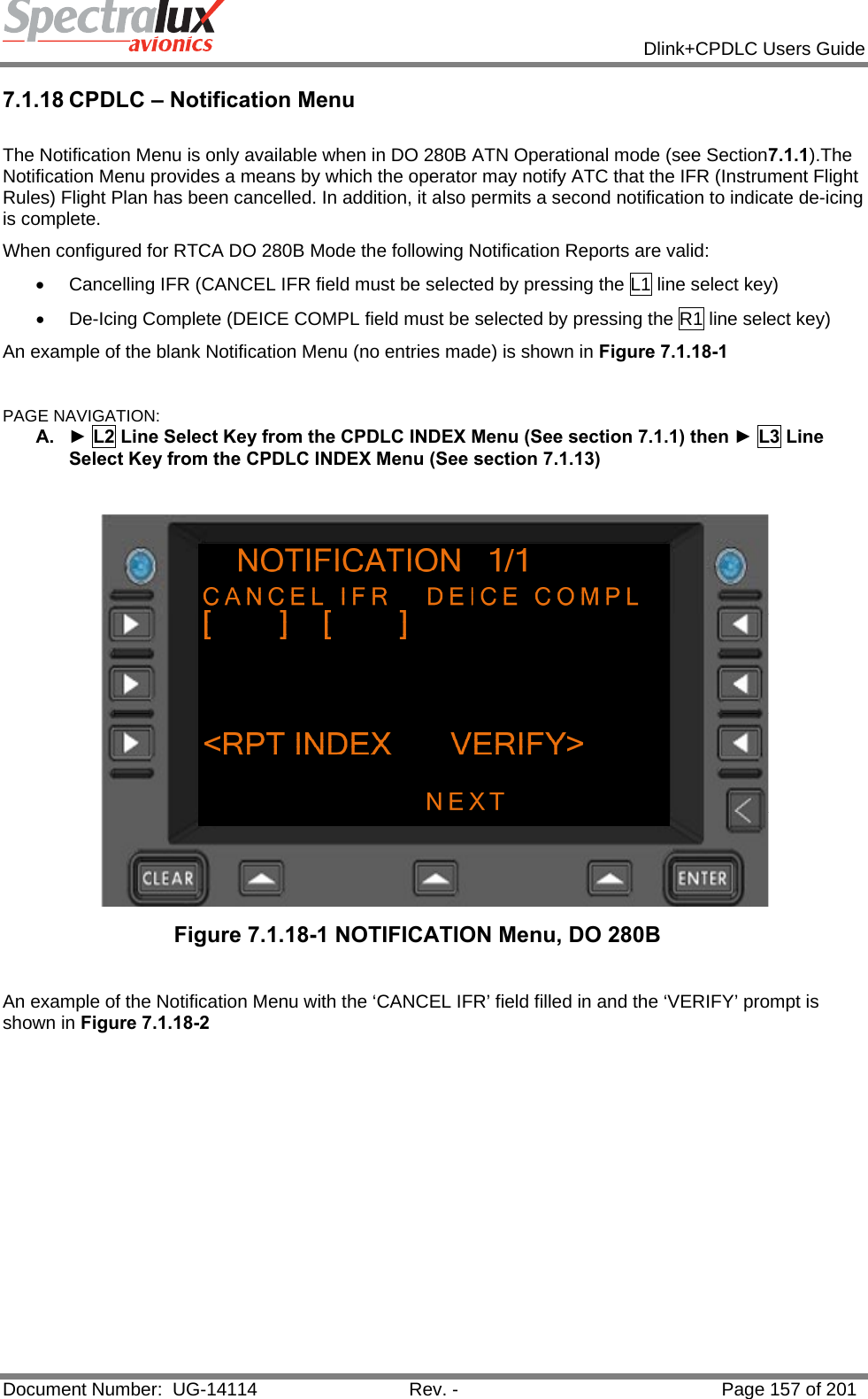
![Dlink+CPDLC Users Guide Document Number: UG-14114 Rev. - Page 183 of 201 Uplink Message Element Message Element Format Message Intent 51 CROSS XYZ AT 1232 CROSS [position] AT [time] - Instruction that the specified position is to be crossed at the specified time. 52 CROSS XYZ AT OR BEFORE 1232 CROSS [position] AT OR BEFORE [time] -Instruction that the specified position is to be crossed at or before the specified time. 53 CROSS XYZ AT OR AFTER 1232 CROSS [position] AT OR AFTER [time] -Instruction that the specified position is to be crossed at or after the specified time. 54 CROSS XYZ BETWEEN 1230 AND 1250 CROSS [position] BETWEEN [time] AND [time] -Instruction that the specified position is to be crossed at or after the specified time. 55 CROSS XYZ AT 200KTS CROSS [position] AT [speed] - Instruction that the specified position is to be crossed at the specified speed and the specified speed is to be maintained until further advised. 56 CROSS XYZ AT OR LESS THAN 200KTS CROSS [position] AT OR LESS THAN [speed] -Instruction that the specified position is to be crossed at a speed equal to or less than the specified speed and the specified speed or less is to be maintained until further advised. 57 CROSS XYZ AT OR GREATER THAN 200KTS CROSS [position] AT OR GREATER THAN [speed] - Instruction that the specified position is to be crossed at a speed equal to or greater than the specified speed and the specified speed or greater is to be maintained until further advised. 58 CROSS XYZ AT 1232 AT 25000FT CROSS [position] AT [time] AT [level] - Instruction that the specified position is to be crossed at the specified time and the specified level. 59 CROSS XYZ AT OR BEFORE 1232 AT 25000FT CROSS [position] AT OR BEFORE [time] AT [level] - Instruction that the specified position is to be crossed at or before the specified time and at the specified level. 60 CROSS XYZ AT OR AFTER 1232 AT 25000FT CROSS [position] AT OR AFTER [time] AT [level] - Instruction that the specified position is to be crossed at or after the specified time and at the specified level. 61 CROSS XYZ AT AND MAINTAIN 25000FT AT 200KTS CROSS [position] AT AND MAINTAIN [level] AT [speed] - Instruction that the specified position is to be crossed at the specified level and speed, and the level and speed are to be maintained. 62 AT 1232 CROSS XYZ AT AND MAINTAIN 25000FT AT [time] CROSS [position] AT AND MAINTAIN [level] - Instruction that at the specified time the specified position is to be crossed at the specified level and the level is to be maintained. 63 AT 1232 CROSS XYZ AT AND MAINTAIN 25000FT AT 200KTS AT [time] CROSS [position] AT AND MAINTAIN [level] AT [speed] - Instruction that at the specified time the specified position is to be crossed at the specified level and speed, and the level and speed are to be maintained. 64 OFFSET 200KM LEFT OF ROUTE OFFSET [specifiedDistance] [direction] OF ROUTE -Instruction to fly a parallel track to the cleared route at a displacement of the specified distance in the specified direction. 65 AT XYZ OFFSET 200KM LEFT OF ROUTE AT [position] OFFSET [specifiedDistance] [direction] OF ROUTE - Instruction to fly a parallel track to the cleared route at a displacement of the specified distance in the specified direction and commencing at the specified position.](https://usermanual.wiki/Spectralux/14114.Users-Manual-2/User-Guide-1874938-Page-81.png)
![Dlink+CPDLC Users Guide Document Number: UG-14114 Rev. - Page 184 of 201 Uplink Message Element Message Element Format Message Intent 66 AT 1232 OFFSET 200KM LEFT OF ROUTE AT [time] OFFSET [specifiedDistance] [direction] OF ROUTE - Instruction to fly a parallel track to the cleared route at a displacement of the specified distance in the specified direction and commencing at the specified time. 67 PROCEED BACK ON ROUTE PROCEED BACK ON ROUTE - Instruction that the cleared flight route is to be rejoined. 68 REJOIN ROUTE BY XYZ REJOIN ROUTE BY [position] - Instruction that the cleared flight route is to be rejoined at or before the specified position. 69 REJOIN ROUTE BY 1232 REJOIN ROUTE BY [time] - Instruction that the cleared flight route is to be rejoined at or before the specified time. 70 EXPECT BACK ON ROUTE BY XYZ EXPECT BACK ON ROUTE BY [position] -Notification that a clearance may be issued to enable the aircraft to rejoin the cleared route at or before the specified position. 71 EXPECT BACK ON ROUTE BY 1232 EXPECT BACK ON ROUTE BY [time] -Notification that a clearance may be issued to enable the aircraft to rejoin the cleared route at or before the specified time. 72 RESUME OWN NAVIGATION RESUME OWN NAVIGATION - Instruction to resume own navigation following a period of tracking or heading clearances. May be used in conjunction with an instruction on how or where to rejoin the cleared route. 73 EBBU CLEARED TO: AAAAA [DepartureClearance] - Notification to the aircraft of the instructions to be followed from departure until the specified clearance limit. 74 PROCEED DIRECT TO XYZ PROCEED DIRECT TO [position] - Instruction to proceed directly from its present position to the specified position. 75 WHEN ABLE PROCEED DIRECT TO XYZ WHEN ABLE PROCEED DIRECT TO [position] -Instruction to proceed, when able, directly to the specified position. 76 AT 1232 PROCEED DIRECT TO XYZ AT [time] PROCEED DIRECT TO [position] - Instruction to proceed, at the specified time, directly to the specified position. 77 AT ABA PROCEED DIRECT TO XYZ AT [position] PROCEED DIRECT TO [position] -Instruction to proceed, at the specified position, directly to the next specified position. 78 AT 25000FT PROCEED DIRECT TO XYZ AT [level] PROCEED DIRECT TO [position] -Instruction to proceed, upon reaching the specified level, directly to the specified position. 79 CLEARED TO XYZ VIA -options selected in the route clearance will be viewable when the message is opened from the CPDLC message log CLEARED TO [position] VIA [routeClearance] -Instruction to proceed to the specified position via the specified route. 80 CLEARED -options selected in the route clearance will be viewable when the message is opened from the CPDLC message log CLEARED [routeClearance] - Instruction to proceed via the specified route. 81 CLEARED ARRIVAL, XYZ.ABC CLEARED [procedureName] - Instruction to proceed in accordance with the specified procedure. 82 CLEARED TO DEVIATE UP TO 200KM LEFT OF ROUTE CLEARED TO DEVIATE UP TO [specifiedDistance] [direction] OF ROUTE - Approval to deviate up to the specified distance from the cleared route in the specified](https://usermanual.wiki/Spectralux/14114.Users-Manual-2/User-Guide-1874938-Page-82.png)
![Dlink+CPDLC Users Guide Document Number: UG-14114 Rev. - Page 185 of 201 Uplink Message Element Message Element Format Message Intent direction. 83 AT XYZ CLEARED -options selected in the route clearance will be viewable when the message is opened from the CPDLC message log AT [position] CLEARED [routeClearance] -Instruction to proceed from the specified position via the specified route. 84 AT XYZ CLEARED ARRIVAL, XYZ.ABC AT [position] CLEARED [procedureName] -Instruction to proceed from the specified position via the specified procedure. 85 EXPECT -options selected in the route clearance will be viewable when the message is opened from the CPDLC message log EXPECT [routeClearance] - Notification that a clearance to fly on the specified route may be issued. 86 AT XYZ EXPECT -options selected in the route clearance will be viewable when the message is opened from the CPDLC message log AT [position] EXPECT [routeClearance] - Notification that a clearance to fly on the specified route from the specified position may be issued. 87 EXPECT DIRECT TO XYZ EXPECT DIRECT TO [position] – Notification that a clearance to fly directly to the specified position may be issued. 88 AT ABA EXPECT DIRECT TO XYZ AT [position] EXPECT DIRECT TO [position] -Notification that a clearance to fly directly from the first specified position to the next specified position may be issue 89 AT 1232 EXPECT DIRECT TO XYZ AT [time] EXPECT DIRECT TO [position] -Notification that a clearance to fly directly to the specified position commencing at the specified time may be issued. 90 AT 25000FT EXPECT DIRECT TO XYZ AT [level] EXPECT DIRECT TO [position] -Notification that a clearance to fly directly to the specified position commencing when the specified level is reached may be issued. 91 HOLD AT XYZ MAINTAIN 25000FT INBOUND TRACK 010T LEFT TURNS 100KM HOLD AT [position] MAINTAIN [level] INBOUND TRACK [degrees][direction] TURNS [legtype] -Instruction to enter a holding pattern with the specified characteristics at the specified position and level. 92 HOLD AT XYZ AS PUBLISHED MAINTAIN 25000FT HOLD AT [position] AS PUBLISHED MAINTAIN [level] - Instruction to enter a holding pattern with the published characteristics at the specified position and level. 93 EXPECT FURTHER CLEARANCE AT 1232 EXPECT FURTHER CLEARANCE AT [time] -Notification that an onwards clearance may be issued at the specified time. 94 TURN LEFT HEADING 010T TURN [direction] HEADING [degrees] - Instruction to turn left or right as specified on to the specified heading. 95 TURN LEFT GROUND TRACK 010T TURN [direction] GROUND TRACK [degrees] -Instruction to turn left or right as specified on to the specified track. 96 CONTINUE PRESENT HEADING CONTINUE PRESENT HEADING - Instruction to turn left or right as specified on to the specified track. 97 AT XYZ FLY HEADING 010T AT [position] FLY HEADING [degrees] -Instruction to continue to fly on the current heading. 98 IMMEDIATELY TURN LEFT HEADING 010T IMMEDIATELY TURN [direction] HEADING [degrees] - Instruction to turn immediately left or right as specified on to the specified heading. 99 EXPECT ARRIVAL, XYZ.ABC EXPECT [procedureName] - Notification that a clearance may be issued for the aircraft to fly the specified](https://usermanual.wiki/Spectralux/14114.Users-Manual-2/User-Guide-1874938-Page-83.png)
![Dlink+CPDLC Users Guide Document Number: UG-14114 Rev. - Page 186 of 201 Uplink Message Element Message Element Format Message Intent procedure. 100 AT 1232 EXPECT 200KTS AT [time] EXPECT [speed] - Notification that a speed instruction may be issued to be effective at the specified time. 101 AT XYZ EXPECT 200KTS AT [position] EXPECT [speed] - Notification that a speed instruction may be issued to be effective at the specified position. 102 AT 25000FT EXPECT 200KTS AT [level] EXPECT [speed] - Notification that a speed instruction may be issued to be effective at the specified level. 103 AT 1232 EXPECT 200KTS TO 100KTS AT [time] EXPECT [speed] TO [speed] -Notification that a speed range instruction may be issued to be effective at the specified time. 104 AT XYZ EXPECT 200KTS TO 100KTS AT [position] EXPECT [speed] TO [speed] -Notification that a speed range instruction may be issued to be effective at the specified position. 105 AT 25000FT EXPECT 200KTS TO 100KTS AT [level] EXPECT [speed] TO [speed] -Notification that a speed range instruction may be issued to be effective at the specified level. 106 MAINTAIN 200KTS MAINTAIN [speed] - Instruction that the specified speed is to be maintained. 107 MAINTAIN PRESENT SPEED MAINTAIN PRESENT SPEED - Instruction that the present speed is to be maintained. 108 MAINTAIN 200KTS OR GREATER MAINTAIN [speed] OR GREATER - Instruction that the specified speed or a greater speed is to be maintained. 109 MAINTAIN 200KTS OR LESS MAINTAIN [speed] OR LESS - Instruction that the specified speed or a lesser speed is to be maintained. 110 MAINTAIN 200KTS TO 100KTS MAINTAIN [speed] TO [speed] - Instruction that a speed within the specified range is to be maintained. 111 INCREASE SPEED TO 200KTS INCREASE SPEED TO [speed] - Instruction that the present speed is to be increased to the specified speed and maintained until further advised. 112 INCREASE SPEED TO 200KTS OR GREATER INCREASE SPEED TO [speed] OR GREATER -Instruction that the present speed is to be increased to the specified speed or greater, and maintained at or above the specified speed until further advised. 113 REDUCE SPEED TO 200KTS REDUCE SPEED TO [speed] - Instruction that the present speed is to be reduced to the specified speed and maintained until further advised. 114 REDUCE SPEED TO 200KTS OR LESS REDUCE SPEED TO [speed] OR LESS -Instruction that the present speed is to be reduced to the specified speed or less and maintained at or below the specified speed until further advised. 115 DO NOT EXCEED 200KTS DO NOT EXCEED [speed] - Instruction that the specified speed is not to be exceeded. 116 RESUME NORMAL SPEED RESUME NORMAL SPEED - Notification that the aircraft need no longer comply with the previously issued speed restriction. 117 CONTACT LFRR CENTER 136.975MHZ CONTACT [unitname] [frequency] - Instruction that the ATS unit with the specified ATS unit name is to be contacted on the specified frequency.](https://usermanual.wiki/Spectralux/14114.Users-Manual-2/User-Guide-1874938-Page-84.png)
![Dlink+CPDLC Users Guide Document Number: UG-14114 Rev. - Page 187 of 201 Uplink Message Element Message Element Format Message Intent 118 AT XYZ CONTACT EBBU CENTER 136.975MHZ AT [position] CONTACT [unitname] [frequency] -Instruction that at the specified position the ATS unit with the specified ATS unit name is to be contacted on the specified frequency. 119 AT 1232 CONTACT EBBU CENTER 136.975MHZ AT [time] CONTACT [unitname] [frequency] -Instruction that at the specified time the ATS unit with the specified ATS unit name is to be contacted on the specified frequency. 120 MONITOR EBBU CENTER 136.975MHZ MONITOR [unitname] [frequency] – Instruction that the ATS unit with the specified ATS unit name is to be monitored on the specified frequency. 121 AT XYZ MONITOR EBBU CENTER 136.975MHZ AT [position] MONITOR [unitname] [frequency] -Instruction that at the specified position the ATS unit with the specified ATS unit name is to be monitored on the specified frequency. 122 AT 1232 MONITOR EBBU CENTER 136.975MHZ AT [time] MONITOR [unitname] [frequency] -Instruction that at the specified time the ATS unit with the specified ATS unit name is to be monitored on the specified frequency. 123 SQUAWK 0123 SQUAWK [code] - Instruction that the specified code (SSR code) is to be selected. 124 STOP SQUAWK STOP SQUAWK - Instruction that the SSR transponder responses are to be disabled. 125 SQUAWK MODE CHARLIE SQUAWK MODE CHARLIE - Instruction that the SSR transponder responses should include level information. 126 SQUAWK MODE CHARLIE STOP SQUAWK MODE CHARLIE - Instruction that the SSR transponder responses should no longer include level information. 127 Report Back On Route Report Back On Route - Instruction to report when the aircraft is back on the cleared route. 128 Report Leaving 25000FT Report Leaving [LEVEL] - Instruction to report when the aircraft has left the specified level. 129 Report Leaving 25000FT Report Maintaining [LEVEL] - Instruction to report when the aircraft is in level flight at the specified level. 130 Report Passing XYZ Report Passing [POSITION] - Instruction to report when the aircraft has passed the specified position. 132 Report Position Report Position - Instruction to report the present position. 133 Report Present Level Report Present Level - Instruction to report the present level. 135 Confirm Assigned Level Confirm Assigned Level - Instruction to confirm and acknowledge the currently assigned level. 136 Confirm Assigned Level Confirm Assigned Speed - Instruction to confirm and acknowledge the currently assigned speed. 138 Confirm Time Over reported Waypoint Confirm Time Over reported Waypoint -Instruction to confirm the previously reported time over the last reported waypoint. 139 Confirm Reported Waypoint Confirm Reported Waypoint - Instruction to confirm the identity of the previously reported waypoint. 140 Confirm Next Waypoint Confirm Next Waypoint - Instruction to confirm the identity of the next waypoint.](https://usermanual.wiki/Spectralux/14114.Users-Manual-2/User-Guide-1874938-Page-85.png)
![Dlink+CPDLC Users Guide Document Number: UG-14114 Rev. - Page 188 of 201 Uplink Message Element Message Element Format Message Intent 141 Confirm Next Waypoint ETA Confirm Next Waypoint ETA - Instruction to confirm the previously reported estimated time at the next waypoint. 142 Confirm Next Waypoint ETA Confirm Ensuing Waypoint - Instruction to confirm the identity of the next but one waypoint. 144 Confirm Squawk Confirm Squawk - Instruction to report the selected (SSR) code. 145 Report Heading Report Heading - Instruction to report the present heading. 146 Report Ground Track Report Ground Track - Instruction to report the present ground track. 147 Request Position Report Request Position Report - Instruction to make a position report. 148 When Can You Accept 25000FT When Can You Accept [LEVEL] - Request for the earliest time at which the specified level can be accepted. 151 When Can You Accept 200KTS When Can You Accept [SPEED] - Instruction to report the earliest time when the specified speed can be accepted. 152 When Can You Accept 200KM LEFT Offset When Can You Accept [SPECIFIED DISTANCE] [DIRECTION] Offset - Instruction to report the earliest time when the specified offset track can be accepted. 153 ALTIMETER 23.00HG ALTIMETER [altimeter] - ATS advisory that the altimeter setting should be the specified setting. 154 RADAR SERVICE TERMINATED RADAR SERVICE TERMINATED – ATS advisory that the radar service is terminated. 155 RADAR CONTACT XYZ RADAR CONTACT [position] - ATS advisory that radar contact has been established at the specified position. 156 RADAR CONTACT LOST RADAR CONTACT LOST - ATS advisory that radar contact has been lost. 157 CHECK STUCK MICROPHONE 136.975MHZ CHECK STUCK MICROPHONE [frequency] -Instruction that a continuous transmission is detected on the specified frequency. Check the microphone button. 158 CHECK STUCK MICROPHONE 136.975MHZ ATIS [atiscode] - ATS advisory that the ATIS information identified by the specified code is the current ATIS information. 159 ERROR INSUFFICIENT RESOURCES ERROR [errorInformation] - A system generated message notifying that the ground system has detected an error. 160 A UM160 WILL NOT SHOW UP IN THE CPDLC MESSAGE LOG. WHEN ONE IS RECEIVED THE ‘NEXT DATA AUTH’ FIELD ON SCREEN B OF THE ‘CM LOGON’ PAGE WILL CONTAIN A FACILITY ID OF THE NEXT DATA AUTORITY. NEXT DATA AUTHORITY [facility] – Notification to the avionics that the specified data authority is the next data authority. If no data authority is specified, this indicates that any previously specified next data authority is no longer valid. 161 END SERVICE END SERVICE - Notification to the avionics that the data link connection with the current data authority is being terminated. 162 MESSAGE NOT SUPPORTED BY THIS ATS UNIT MESSAGE NOT SUPPORTED BY THIS ATS UNIT - Notification that the ground system does not support this message. 163 LFRR [facilitydesignation] - Notification to the pilot of an ATSU identifier. 164 WHEN READY WHEN READY - The associated instruction may be complied with at any future time.](https://usermanual.wiki/Spectralux/14114.Users-Manual-2/User-Guide-1874938-Page-86.png)
![Dlink+CPDLC Users Guide Document Number: UG-14114 Rev. - Page 189 of 201 Uplink Message Element Message Element Format Message Intent 165 THEN THEN - Used to link two messages, indicating the proper order of execution of clearances/ instructions. 166 DUE TO CROSSING TRAFFIC DUE TO [traffictype]TRAFFIC - The associated instruction is issued due to traffic considerations. 167 DUE TO AIRSPACE RESTRICTION DUE TO AIRSPACE RESTRICTION – The associated instruction is issued due to airspace restrictions. 168 DISREGARD DISREGARD - The indicated communication should be ignored. 169 Up to 256 alpha-numeric characters and symbols [freetext] 170 Up to 256 alpha-numeric characters and symbols [freetext] 171 CLIMB AT 20000FPM MINIMUM CLIMB AT [verticalRate] MINIMUM – Instruction to climb at not less than the specified rate. 172 CLIMB AT 25000FPM MAXIMUM CLIMB AT [verticalRate] MAXIMUM - Instruction to climb at not above the specified rate. 173 DESCEND AT 7000FPM MINIMUM DESCEND AT [verticalRate] MINIMUM -Instruction to descend at not less than the specified rate. 174 DESCEND AT 15000FPM MAXIMUM DESCEND AT [verticalRate] MAXIMUM -Instruction to descend at not above the specified rate. 175 Report Reaching 25000FT Report Reaching [LEVEL] - Instruction to report when the aircraft has reached the specified level. 176 MAINTAIN OWN SEPARATION AND VMC MAINTAIN OWN SEPARATION AND VMC -Notification that the pilot is responsible for maintaining separation from other traffic and is also responsible for maintaining visual meteorological conditions. 177 AT PILOTS DISCRETION AT PILOTS DISCRETION - Used in conjunction with a clearance/instruction to indicate that the pilot may execute when prepared to do so. 179 SQUAWK IDENT SQUAWK IDENT - Instruction that the ‘ident’ function on the SSR transponder is to be actuated. 180 Report Reaching Block 20000FT to 25000FT Report Reaching Block [LEVEL] to [LEVEL] -Instruction to report when the aircraft is within the specified vertical range. 181 Report Distance TO XYZ Report Distance [TO/FROM] [POSITION] -Instruction to report the present distance to or from the specified position. 182 Confirm ATIS Code Confirm ATIS Code - Instruction to report the identification code of the last ATIS received. 183 Up to 256 alpha-numeric characters and symbols [freetext] 184 At Time 1232 Report Distance FROM XYZ At Time [TIME] Report Distance [TO/FROM] [POSITION] - Instruction to report at the specified time the distance to or from the specified position. 185 AFTER PASSING XYZ CLIMB TO 25000FT AFTER PASSING [position] CLIMB TO [level] -Instruction that after passing the specified position a climb to the specified level is to commence and once reached the specified level is to be maintained. 186 AFTER PASSING XYZ DESCEND TO 20000FT AFTER PASSING [position] DESCEND TO [level] -Instruction that after passing the specified position a descent to the specified level is to commence and once reached the specified level is to be maintained. 187 Up to 256 alpha-numeric characters and symbols [freetext]](https://usermanual.wiki/Spectralux/14114.Users-Manual-2/User-Guide-1874938-Page-87.png)
![Dlink+CPDLC Users Guide Document Number: UG-14114 Rev. - Page 190 of 201 Uplink Message Element Message Element Format Message Intent 188 AFTER PASSING XYZ MAINTAIN 200KTS AFTER PASSING [position] MAINTAIN [speed] -Instruction that after passing the specified position the specified speed is to be maintained. 189 ADJUST SPEED TO 200KTS ADJUST SPEED TO [speed] - Instruction that the present speed is to be changed to the specified speed. 190 FLY HEADING 150T FLY HEADING [degrees] - Instruction to fly on the specifiedheading. 191 ALL ATS TERMINATED ALL ATS TERMINATED - ATS advisory that the aircraft is entering airspace in which no air traffic services are provided and all existing air traffic services are terminated. 192 REACH 25000FT BY 1232 REACH [level] BY [time] - Instruction that a change of level is to continue, but at a rate such that the specified level is reached at or before the specified time. 193 IDENTIFICATION LOST IDENTIFICATION LOST - Notification that radar identification has been lost. 195 Up to 256 alpha-numeric characters and symbols [freetext] 196 Up to 256 alpha-numeric characters and symbols [freetext] 197 Up to 256 alpha-numeric characters and symbols [freetext] 198 Up to 256 alpha-numeric characters and symbols [freetext] 199 Up to 256 alpha-numeric characters and symbols [freetext] 200 Report Reaching Report Reaching - Instruction used in conjunction with a level clearance to report reaching the level assigned. 203 Up to 256 alpha-numeric characters and symbols [freetext] 205 Up to 256 alpha-numeric characters and symbols [freetext] 208 Up to 256 alpha-numeric characters and symbols [freetext] 209 REACH 25000FT BY XYZ REACH [level] BY [position] - Instruction that a change of level is to continue, but at a rate such that the specified level is reached at or before the specified position. 210 IDENTIFIED XYZ IDENTIFIED [position] - ATS advisory that the aircraft has been identified on radar at the specified position. 211 REQUEST FORWARDED REQUEST FORWARDED - Indicates that the ATC has received the request and has passed it to the next control authority. 212 EBBU ATIS A CURRENT [facilitydesignation] ATIS [atiscode] CURRENT -ATS advisory that the specified ATIS information at the specified airport is current. 213 EBBU ALTIMETER 800.0HPA [facilitydesignation] ALTIMETER [altimeter] – ATS advisory that the specified altimeter setting relates to the specified facility. 214 RVR RUNWAY 20L 200FT RVR RUNWAY [runway] [rvr] - ATS advisory that indicates the RVR value for the specified runway. 215 TURN LEFT 200 TURN [direction][degrees] - Instruction to turn a specified number of degrees left or right. 216 Request Flight Plan Request Flight Plan - Instruction to file a flight plan. 217 Report Arrival Report Arrival - Instruction to report that the aircraft has landed.](https://usermanual.wiki/Spectralux/14114.Users-Manual-2/User-Guide-1874938-Page-88.png)
![Dlink+CPDLC Users Guide Document Number: UG-14114 Rev. - Page 191 of 201 Uplink Message Element Message Element Format Message Intent 218 REQUEST ALREADY RECEIVED REQUEST ALREADY RECEIVED - Indicates to the pilot that the request has already been received on the ground. 219 STOP CLIMB AT 25000FT STOP CLIMB AT [level] - Instruction to stop the climb below the previously assigned level. 220 STOP DESCENT AT 25000FT STOP DESCENT AT [level] - Instruction to stop the descent above the previously assigned level. 221 STOP TURN HEADING 150T STOP TURN HEADING [degrees] - Instruction to stop turn at the specified heading prior to reaching the previously assigned heading. 222 NO SPEED RESTRICTION NO SPEED RESTRICTION - Notification that the aircraft may keep its preferred speed without restriction. 223 REDUCE TO MINIMUM APPROACH SPEED REDUCE TO MINIMUM APPROACH SPEED -Instruction to reduce present speed to the minimum safe approach speed. 224 NO DELAY EXPECTED NO DELAY EXPECTED - ATS advisory that no delay is expected. 225 DELAY NOT DETERMINED DELAY NOT DETERMINED - ATS advisory that the expected delay has not been determined. 226 EXPECTED APPROACH TIME 1245 EXPECTED APPROACH TIME [time] – ATS advisory that the aircraft may expect to be cleared to commence its approach procedure at the specified time. 227 LOGICAL ACKNOWLEDGMENT LOGICAL ACKNOWLEDGMENT - Confirmation to the aircraft system that the ground system has received the message to which the logical acknowledgment refers and found it acceptable for display to the responsible person. 228 Report ETA XYZ Report ETA [POSITION] - Instruction to report the estimated time of arrival at the specified position. 229 Report Alternate Aerodrome Report Alternate Aerodrome - Instruction to report the preferred alternate aerodrome for landing. 230 IMMEDIATELY IMMEDIATELY - The associated instruction is to be complied with immediately. 231 State Preferred Level State Preferred Level - Instruction to indicate the pilot’s preferred level. 232 State Top Of Descent State Top Of Descent - Instruction to indicate the pilot’s preferred time and/or position to commence descent to the aerodrome of intended arrival. 233 USE OF LOGICAL ACKNOWLEDGMENT PROHIBITED USE OF LOGICAL ACKNOWLEDGMENT PROHIBITED - Notification to the pilot that messages sent requiring a logical acknowledgment will not be accepted by this ground system. 234 FLIGHT PLAN NOT HELD FLIGHT PLAN NOT HELD - Notification that the ground system does not have a flight plan for that aircraft. 236 LEAVE CONTROLLED AIRSPACE LEAVE CONTROLLED AIRSPACE – Instruction to leave controlled airspace. 237 REQUEST AGAIN WITH NEXT UNIT REQUEST AGAIN WITH NEXT UNIT – Indicates that the request cannot be responded to by the current unit, and that it should be requested from the next unit](https://usermanual.wiki/Spectralux/14114.Users-Manual-2/User-Guide-1874938-Page-89.png)
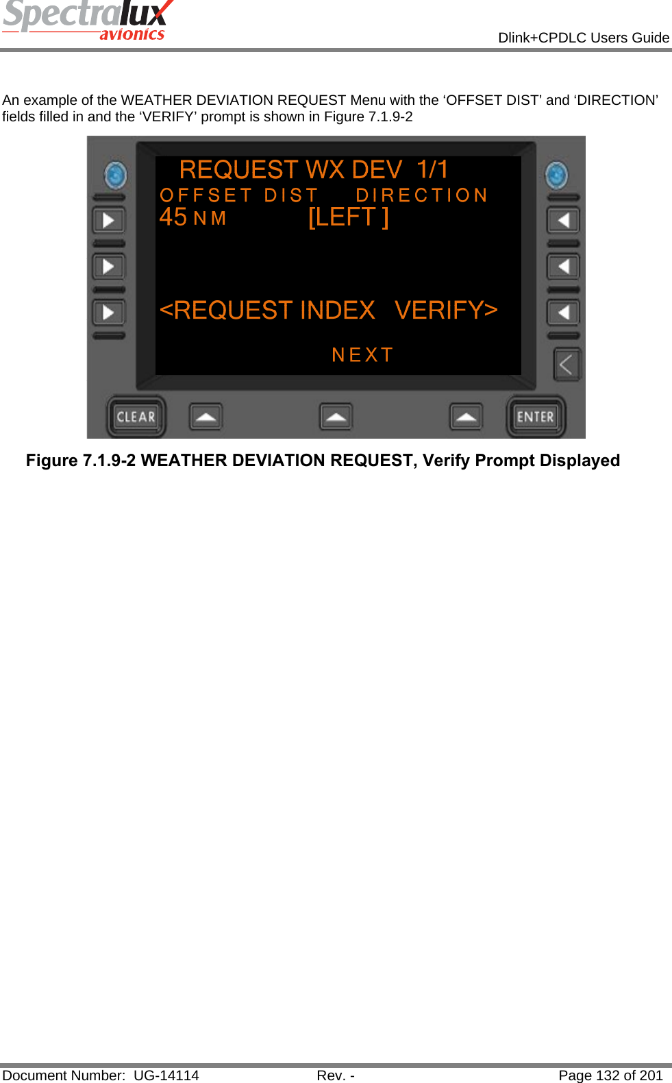
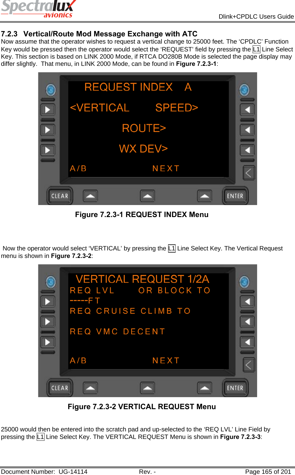
![Dlink+CPDLC Users Guide Document Number: UG-14114 Rev. - Page 192 of 201 7.3.2 Downlink Messages Supported by Dlink+ w/CPDLC The table below defines those downlink messages supported by Dlink+ w/CPDLC when in RTCA DO280B ATN Operational Mode. When in LINK 2000 ATN Operational Mode, supported downlink messages are limited to those messages that are shaded in yellow. (See Section7.1.1) for information on how the ATN Operational Mode can be changed.) Downlink Message Element Message Element Format Message Intent 0 WILCO WILCO - The instruction is understood and will be complied with. 1 UNABLE UNABLE - The instruction cannot be complied with. 2 STANDBY STANDBY - Wait for a reply. 3 ROGER ROGER - Message received and understood. 4 AFFIRM AFFIRM - Yes. 5 NEGATIVE NEGATIVE - No. 6 REQUEST 25000FT REQUEST [level] - Request to fly at the specified level. 7 REQUEST BLOCK 20000FT TO 25000FT REQUEST BLOCK [level] TO [level] - Request to fly at a level within the specified vertical range. 8 REQUEST CRUISE CLIMB TO 25000FT REQUEST CRUISE CLIMB TO [level] – Request to cruise climb to the specified level. 9 REQUEST CLIMB TO 25000FT REQUEST CLIMB TO [level] - Request to climb to the specified level. 10 REQUEST DESCENT TO 20000FT REQUEST DESCENT TO [level] - Request to descend to the specified level. 11 AT XYZ REQUEST CLIMB TO 25000FT AT [position] REQUEST CLIMB TO [level] -Request that at the specified position a climb to the specified level be approved. 12 AT ABC REQUEST DESCENT TO 15000FT AT [position] REQUEST DESCENT TO [level] -Request that at the specified position a descent to the specified level be approved. 13 AT 1254 REQUEST CLIMB TO 25000FT AT [time] REQUEST CLIMB TO [level] – Request that at the specified time a climb to the specified level be approved. 14 AT 1032 REQUEST DESCENT TO 22000FT AT [time] REQUEST DESCENT TO [level] -Request that at the specified time a descent to the specified level be approved. 15 REQUEST OFFSET 200KM LEFT OF ROUTE REQUEST OFFSET [specifiedDistance] [direction] OF ROUTE - Request that a parallel track, offset from the cleared track by the specified distance in the specified direction, be approved. 16 AT ABC REQUEST OFFSET 200KM LEFT OF ROUTE AT [position] REQUEST OFFSET [specifiedDistance] [direction] OF ROUTE -Request that a parallel track, offset from the cleared track by the specified distance in the specified direction, be approved from the specified position. 17 AT 1221 REQUEST OFFSET 150KM RIGHT OF ROUTE AT [time] REQUEST OFFSET [specifiedDistance] [direction] OF ROUTE - Request that a parallel track, offset from the cleared track by the specified distance in the specified direction, be approved from the specified time.](https://usermanual.wiki/Spectralux/14114.Users-Manual-2/User-Guide-1874938-Page-90.png)
![Dlink+CPDLC Users Guide Document Number: UG-14114 Rev. - Page 193 of 201 Downlink Message Element Message Element Format Message Intent 18 REQUEST 200KTS REQUEST [speed] - Request to fly at the specified speed. 19 REQUEST 150KTS TO 200KTS REQUEST [speed] TO [speed] - Request to fly within the specified speed range. 20 REQUEST VOICE CONTACT REQUEST VOICE CONTACT - Request for voice contact. 21 REQUEST VOICE CONTACT 136.975 REQUEST VOICE CONTACT [frequency] -Request for voice contact on the specified frequency. 22 REQUEST DIRECT TO XYZ REQUEST DIRECT TO [position] - Request to track from the present position direct to the specified position. 23 REQUEST ARRIVAL, XYZ.ABC REQUEST [procedureName] - Request for the specified procedure clearance. 25 REQUEST ARRIVAL, XYZ.ABC CLEARANCE REQUEST [clearanceType] CLEARANCE -Request for a clearance. 27 REQUEST WEATHER DEVIATION UP TO 150KM RIGHT OF ROUTE REQUEST WEATHER DEVIATION UP TO [specifiedDistance] [direction] OF ROUTE - Request for a weather deviation up to the specified distance off track in the specified direction. 28 LEAVING 20000FT LEAVING [level] - Notification of leaving the specified level. 29 CLIMBING TO 25000FT CLIMBING TO [level] - Notification of climbing to the specified level. 30 DESCENDING TO 23000FT DESCENDING TO [level] - Notification of descending to the specified level. 31 PASSING XYZ PASSING [position] - Notification of passing the specified position. 32 PRESENT LEVEL 23000FT PRESENT LEVEL [level] - Notification of the present level. 33 PRESENT POSITION XYZ PRESENT POSITION [position] - Notification of the present position. 34 PRESENT SPEED 200KTS PRESENT SPEED [speed] - Notification of the present speed. 35 PRESENT HEADING 150T PRESENT HEADING [degrees] - Notification of the present heading in degrees. 36 PRESENT GROUND TRACK 165 PRESENT GROUND TRACK [degrees] -Notification of the present ground track in degrees. 37 MAINTAINING 23000FT MAINTAINING [level] - Notification that the aircraft is maintaining the specified level. 38 ASSIGNED LEVEL 23000FT ASSIGNED LEVEL [level] - Read-back of the assigned level. 39 ASSIGNED SPEED 200KTS ASSIGNED SPEED [speed] - Read-back of the assigned speed. 41 BACK ON ROUTE BACK ON ROUTE - The aircraft has regained the cleared route. 42 NEXT WAYPOINT DAR NEXT WAYPOINT [position] - The next waypoint is the specified position. 43 NEXT WAYPOINT ETA 1124 NEXT WAYPOINT ETA [time] - The ETA at the next waypoint is as specified. 44 ENSUING WAYPOINT DAR ENSUING WAYPOINT [position] - The next but one](https://usermanual.wiki/Spectralux/14114.Users-Manual-2/User-Guide-1874938-Page-91.png)
![Dlink+CPDLC Users Guide Document Number: UG-14114 Rev. - Page 194 of 201 Downlink Message Element Message Element Format Message Intent waypoint is the specified position. 45 REPORTED WAYPOINT DAR REPORTED WAYPOINT [position] - Clarification of previously reported waypoint passage. 46 REPORTED WAYPOINT 1124 REPORTED WAYPOINT [time] - Clarification of time over previously reported waypoint. 47 SQUAWKING 2130 SQUAWKING [code] - The specified (SSR) code has been selected. 48 POSITION REPORT XYZ POSITION REPORT [positionreport] - Position report. 49 WHEN CAN WE EXPECT 200KTS WHEN CAN WE EXPECT [speed] - Request for the earliest time at which a clearance to the specified speed can be expected. 50 WHEN CAN WE EXPECT 150KTS TO 200KTS WHEN CAN WE EXPECT [speed] TO [speed] -Request for the earliest time at which a clearance to a speed within the specified range can be expected. 51 WHEN CAN WE EXPECT BACK ON ROUTE WHEN CAN WE EXPECT BACK ON ROUTE -Request for the earliest time at which a clearance to regain the planned route can be expected. 52 WHEN CAN WE EXPECT LOWER LEVEL WHEN CAN WE EXPECT LOWER LEVEL -Request for the earliest time at which a clearance to descend can be expected. 53 WHEN CAN WE EXPECT HIGHER LEVEL WHEN CAN WE EXPECT HIGHER LEVEL -Request for the earliest time at which a clearance to climb can be expected. 54 WHEN CAN WE EXPECT CRUISE CLIMB TO 25000FT WHEN CAN WE EXPECT CRUISE CLIMB TO [level] - Request for the earliest time at which a clearance to cruise climb to the specified level can be expected. 62 ERROR INSUFFICIENT RESOURCES ERROR [errorInformation] - A system-generated message that the avionics has detected an error. 63 NOT CURRENT DATA AUTHORITY NOT CURRENT DATA AUTHORITY - A system-generated denial to any CPDLC message sent from a ground facility that is not the current data authority. 65 DUE TO WEATHER DUE TO WEATHER - Used to explain reasons for pilot’s message. 66 DUE TO AIRCRAFT PERFORMANCE DUE TO AIRCRAFT PERFORMANCE - Used to explain reasons for pilot’s message. 67 Up to 256 alpha-numeric characters and symbols [freetext] 69 REQUEST VMC DESCENT REQUEST VMC DESCENT - Request that a descent be approved on a see-and-avoid basis. 70 REQUEST HEADING 150T REQUEST HEADING [degrees] - Request a clearance to adopt the specified heading 71 REQUEST GROUND TRACK 150 REQUEST GROUND TRACK [degrees] – Request a clearance to adopt the specified ground track. 72 REACHING 25000FT REACHING [level] - Notification that the aircraft has reached the specified level. 74 REQUEST TO MAINTAIN OWN SEPARATION AND VMC REQUEST TO MAINTAIN OWN SEPARATION AND VMC - States a desire by the pilot to provide his/her own separation and remain in VMC. 75 AT PILOTS DISCRETION AT PILOTS DISCRETION - Used in conjunction with another message to indicate that the pilot wishes to execute request when the pilot is prepared to do so.](https://usermanual.wiki/Spectralux/14114.Users-Manual-2/User-Guide-1874938-Page-92.png)
![Dlink+CPDLC Users Guide Document Number: UG-14114 Rev. - Page 195 of 201 Downlink Message Element Message Element Format Message Intent 76 REACHING BLOCK 23000FT TO 25000FT REACHING BLOCK [level] TO [level] -Notification that the aircraft has reached a level within the specified vertical range. 77 ASSIGNED BLOCK 23000FT TO 25000FT ASSIGNED BLOCK [level] TO [level] - Read-back of the assigned vertical range. 78 AT 1241 200KM TO XYZ AT [time] [distance] [tofrom] [position] -Notification that at the specified time, the aircraft’s position was as specified. 79 ATIS X ATIS [atiscode] - The code of the latest ATIS received is as specified. 81 WE CAN ACCEPT 25000FT AT 1024 WE CAN ACCEPT [level] AT [time] - We can accept the specified level at the specified time. 82 WE CANNOT ACCEPT 100000FT WE CANNOT ACCEPT [level] -We cannot accept the specified level. 83 WE CAN ACCEPT 200KTS AT 1130 WE CAN ACCEPT [speed] AT [time] - We can accept the specified speed at the specified time. 84 WE CANNOT ACCEPT 700KTS WE CANNOT ACCEPT [speed] - We cannot accept the specified speed. 85 WE CAN ACCEPT 200KM RIGHT AT 1135 WE CAN ACCEPT [specifiedDistance] [direction] AT [time] - We can accept a parallel track offset the specified distance in the specified direction at the specified time. 86 WE CANNOT ACCEPT 500KM RIGHT WE CANNOT ACCEPT [specifiedDistance] [direction] - We cannot accept a parallel track offset the specified distance in the specified direction. 87 WHEN CAN WE EXPECT CLIMB TO 20000FT WHEN CAN WE EXPECT CLIMB TO [level] -Request for the earliest time at which a clearance to climb to the specified level can be expected. 88 WHEN CAN WE EXPECT DESCENT TO 1000FT WHEN CAN WE EXPECT DESCENT TO [level] -Request for the earliest time at which a clearance to descend to the specified level can be expected. 89 MONITORING EBBU CENTER 136.975 MONITORING [unitname] [frequency] – The specified ATS unit is being monitored on the specified frequency. 98 Up to 256 alpha-numeric characters and symbols [freetext] 99 THIS DOWNLINK WILL NOT SHOW UP IN THE CPDLC MESSAGE LOG. WHEN ONE IS RECEIVED THE NEXT DATA AUTHORITY BECOMES THE CURRENT DATA AUTHORITY. THIS IS VIEWABLE THROUGH THE ‘CURNT DATA AUTH’ FIELD ON SCREEN B OF THE ‘CM LOGON’ PAGE. CURRENT DATA AUTHORITY - A system-generated message to inform a ground facility that it is now the current data authority 100 LOGICAL ACKNOWLEDGMENT LOGICAL ACKNOWLEDGMENT – Confirmation to the ground system that the aircraft system has received the message to which the logical acknowledgment refers and found it acceptable for display to the responsible person. 102 LANDING REPORT LANDING REPORT - Used to report that an aircraft has landed. 103 CANCELLING IFR CANCELLING IFR - Allows the pilot to indicate that he/she has cancelled IFR flight plan. 104 ETA XYZ 1234 ETA[position][time] - Notification of estimated time of arrival at the specified position. 105 ALTERNATE AERODROME EBBU ALTERNATE AERODROME[airport] - Notification of the alternative aerodrome for landing.](https://usermanual.wiki/Spectralux/14114.Users-Manual-2/User-Guide-1874938-Page-93.png)
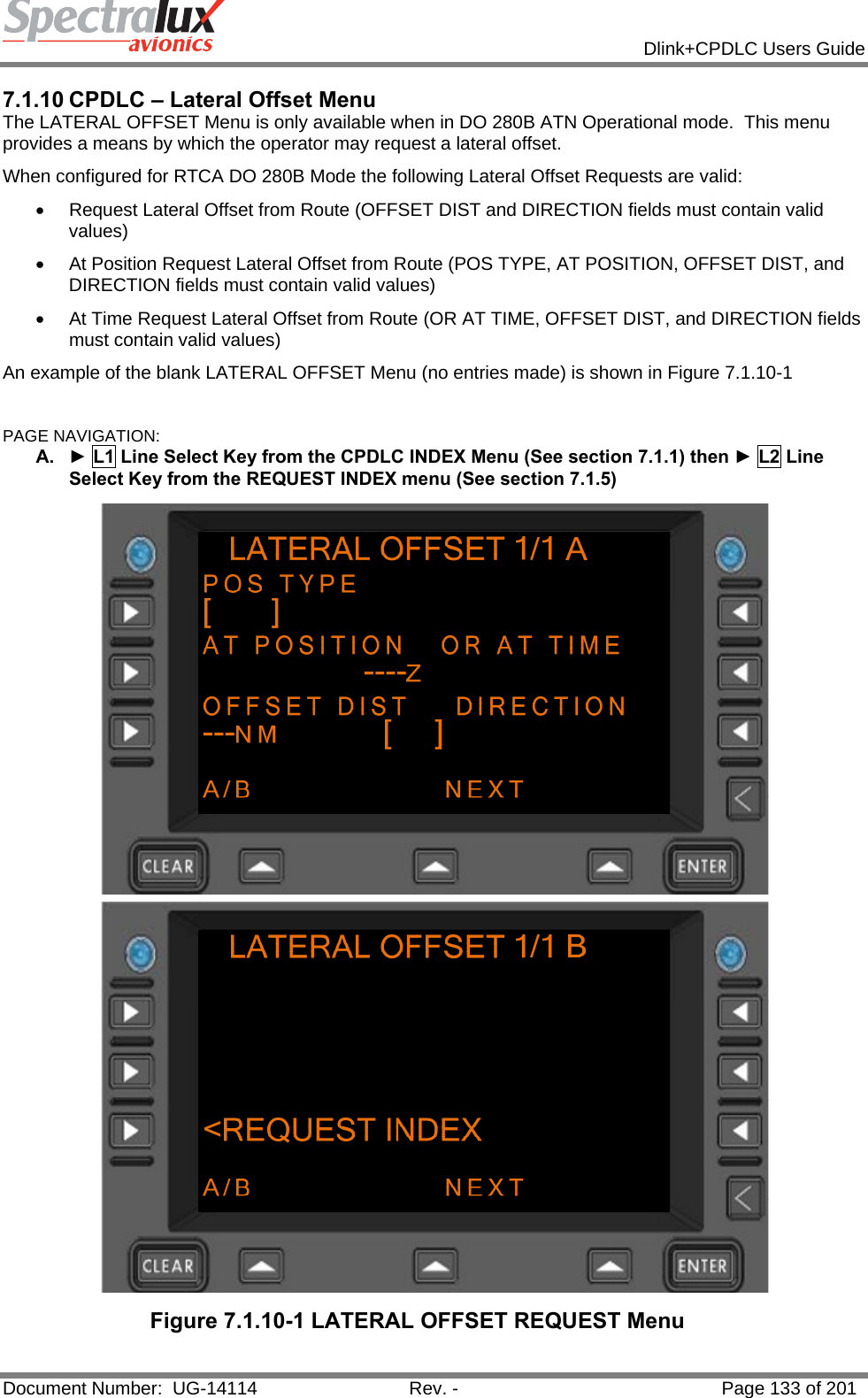
![Dlink+CPDLC Users Guide Document Number: UG-14114 Rev. - Page 196 of 201 Downlink Message Element Message Element Format Message Intent 106 PREFERRED LEVEL 25000FT PREFERRED LEVEL[level] - Notification of the preferred level. 107 NOT AUTHORIZED NEXT DATA AUTHORITY NOT AUTHORIZED NEXT DATA AUTHORITY – A system-generated message sent to a ground system that tries to connect to an aircraft when a current data authority has not designated the ground system as the NDA. 108 DE-ICING COMPLETE DE-ICING COMPLETE - Notification that de-icing action has been completed. 109 TOP OF DESCENT 1237 TOP OF DESCENT [time] - Notification of the preferred time to commence descent for approach. 110 TOP OF DESCENT XYZ TOP OF DESCENT [position] - Notification of the preferred position to commence descent for approach. 111 TOP OF DESCENT 1200 XYZ TOP OF DESCENT [time] [position] - Notification of the preferred time and position to commence descent for approach.](https://usermanual.wiki/Spectralux/14114.Users-Manual-2/User-Guide-1874938-Page-94.png)