Spectralux 14114 Dlink+ w/CPDLC. All-in-one data communications, CPDLC and ACARS in a single LRU User Manual 1
Spectralux Corporation Dlink+ w/CPDLC. All-in-one data communications, CPDLC and ACARS in a single LRU Users Manual 1
Contents
- 1. Installation Manual
- 2. Users Manual 1
- 3. Users Manual 2
- 4. Users Manual
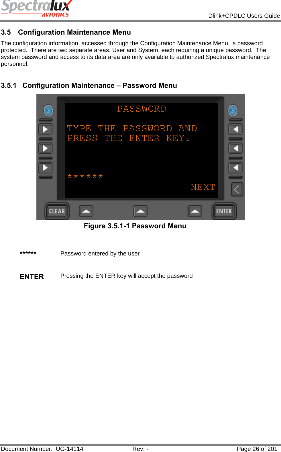
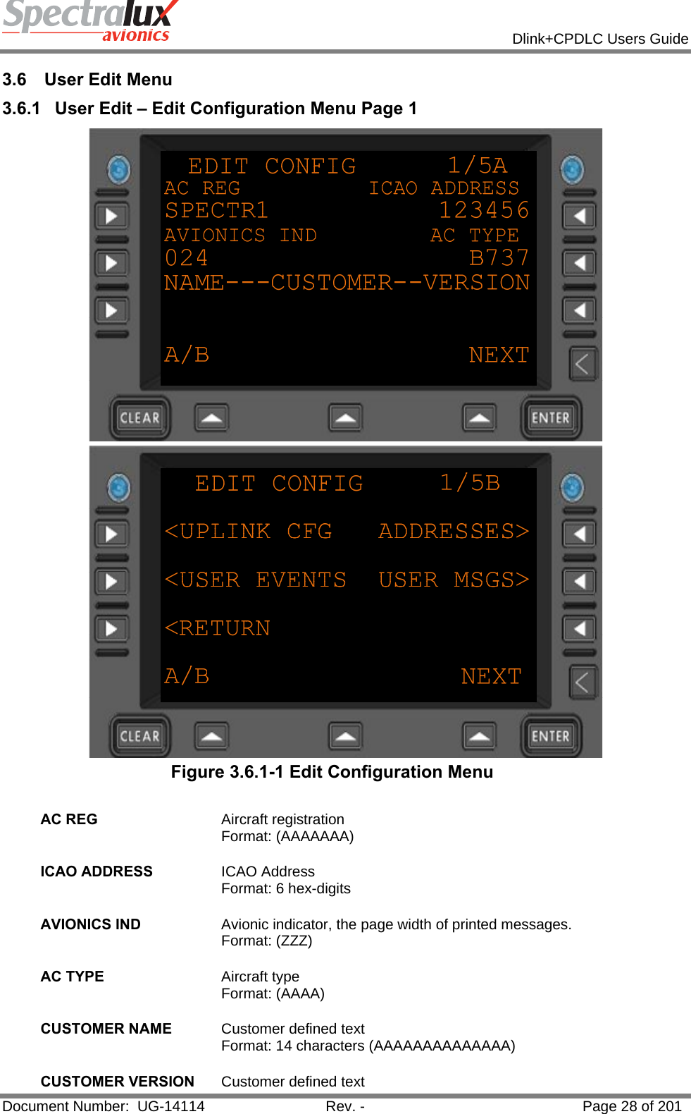
Users Manual 1
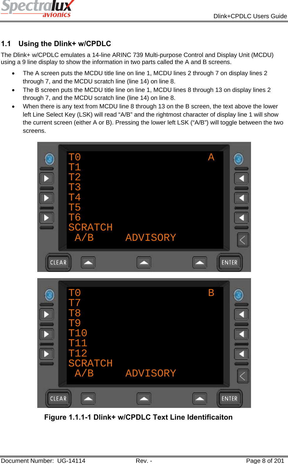
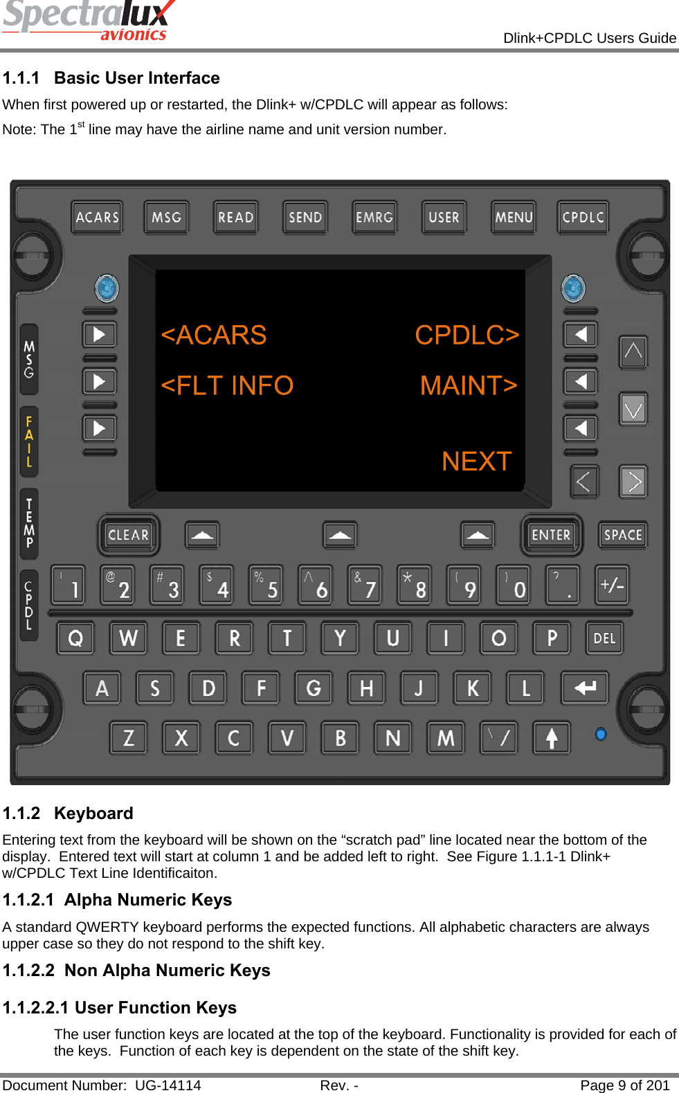
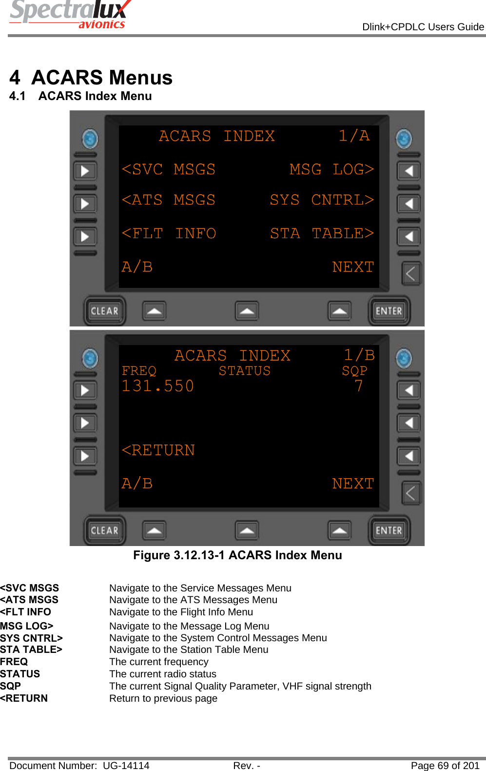
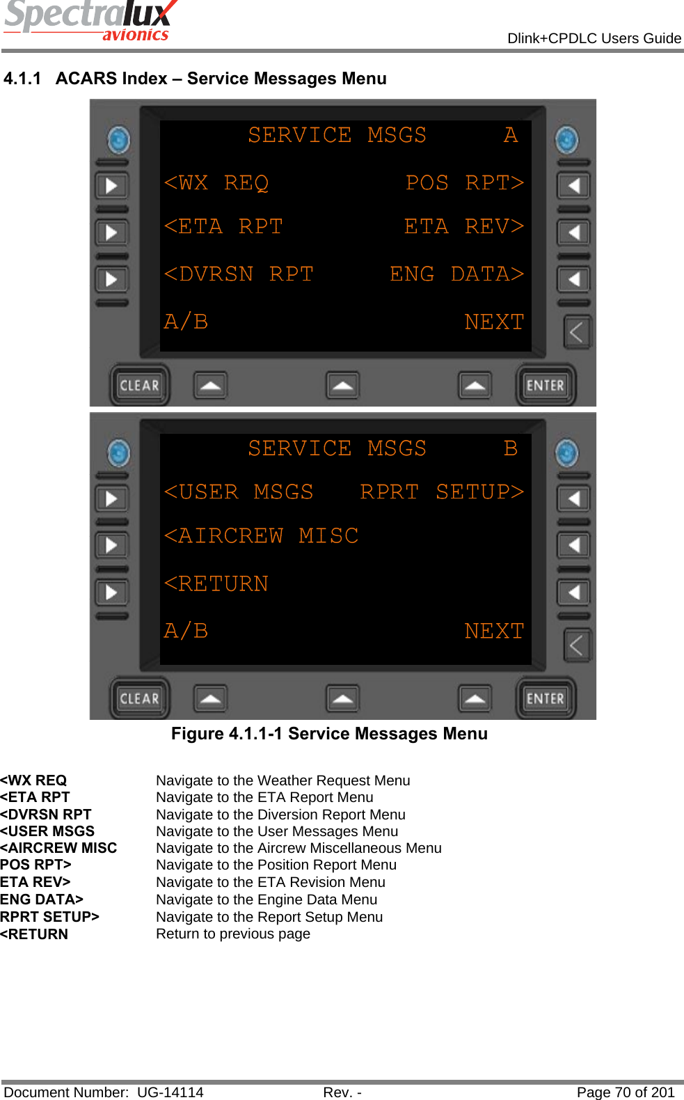
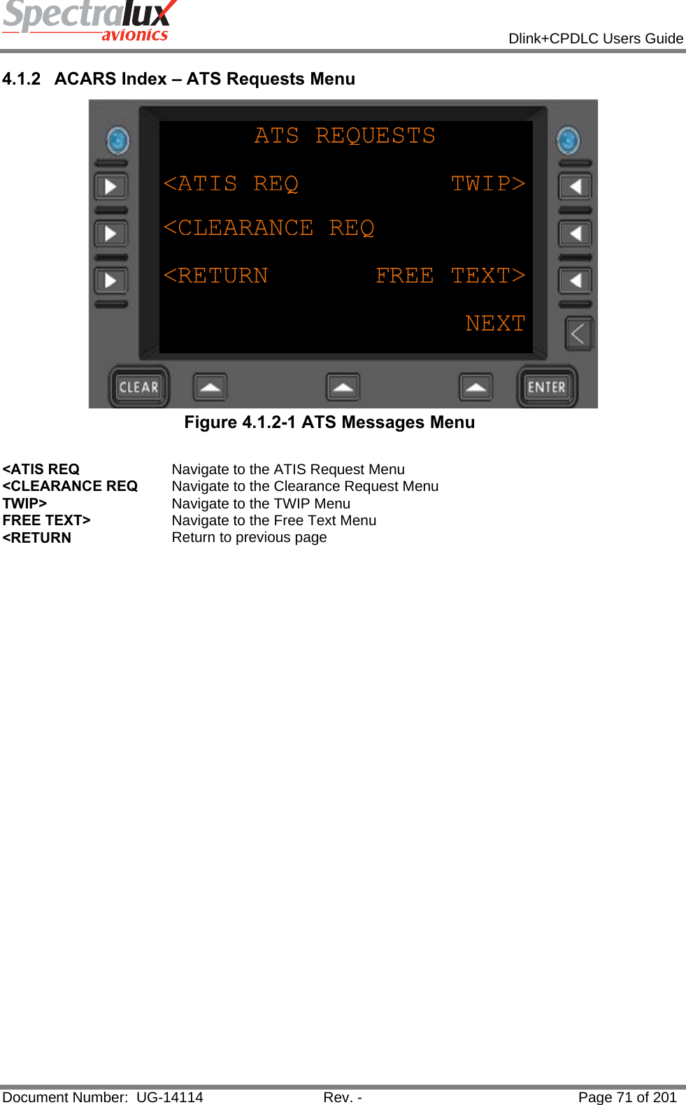
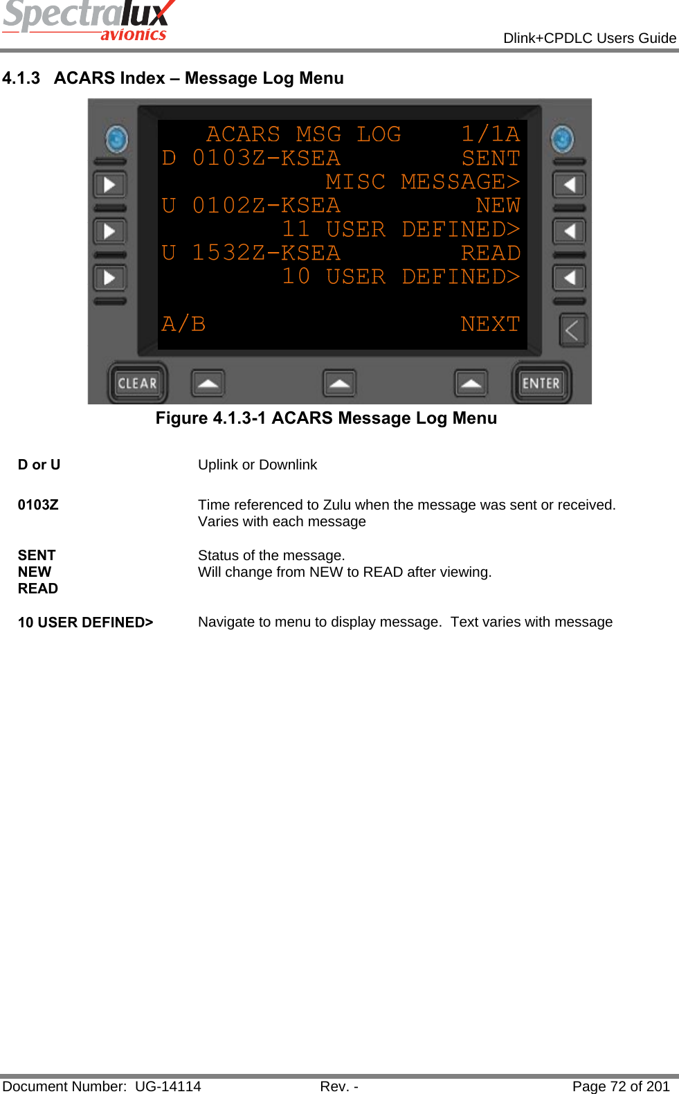
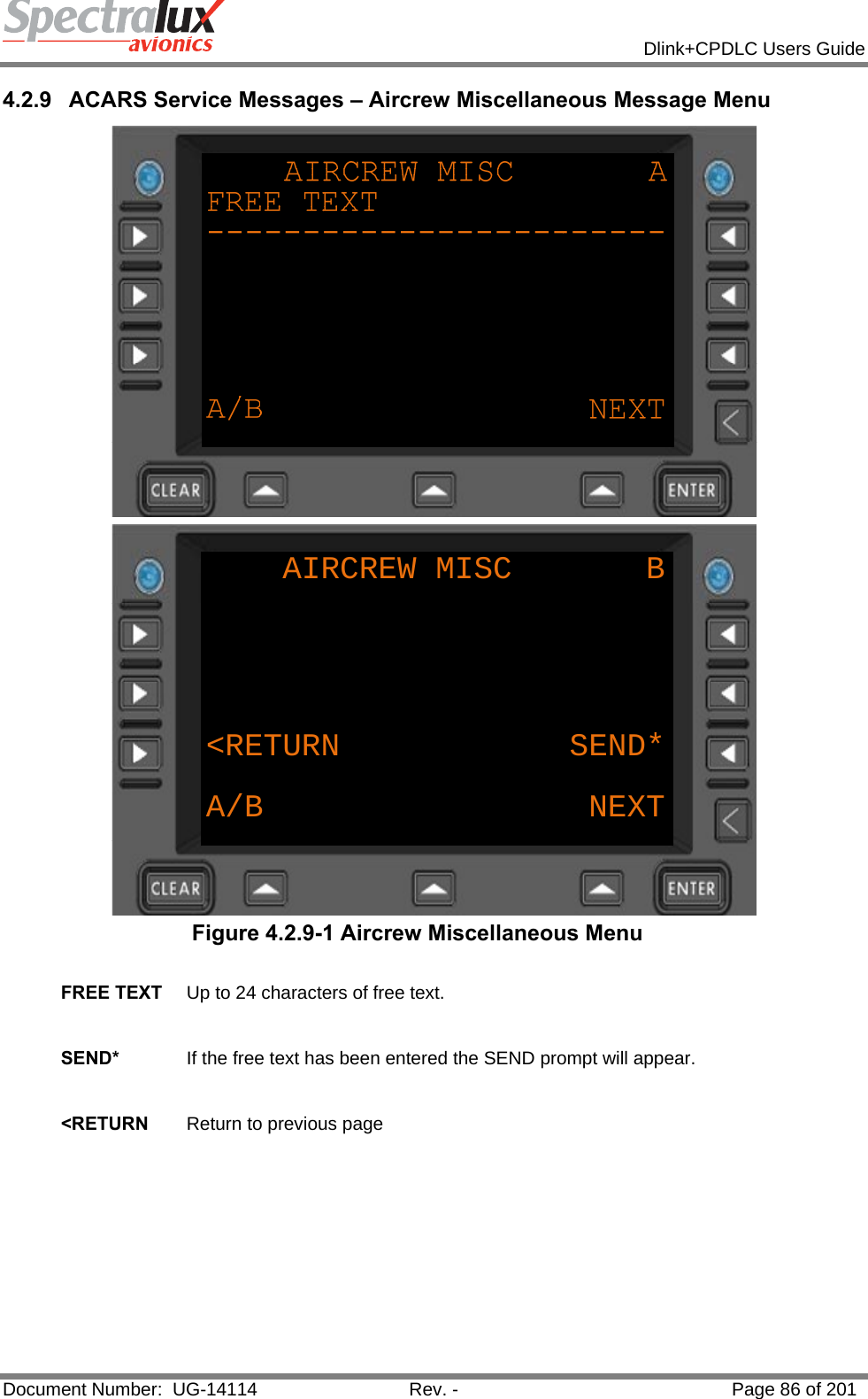
![Dlink+CPDLC Users Guide Document Number: UG-14114 Rev. - Page 10 of 201 Functions associated with each non-shifted User Function Key: • ACARS – Displays the ACARS Index Menu. • MSG – Displays the ACARS messages log. • READ – Displays the Monitor menu page. • SEND – Displays the Aircrew Miscellaneous Message page. • EMRG – Displays the E7500 Menu. • USER – Displays the Main System User Menu. • MENU – Displays the Subsystem Menu. • CPDLC – Displays the CPDLC Index Menu. The following functions associated with each shifted User Function Key: • ACARS – Displays the ACARS Index Menu. • MSG – Displays the ACARS messages log. • READ – Displays the Station Table Menu. • SEND – Displays the ATS Free Text Menu. • EMRG – Displays the E7500 Menu • USER – Print the current ACARS message if displayed else print current menu. • MENU – Displays the Subsystem Menu. • CPDLC – Displays the CPDLC Index Menu. Pressing the MENU user key selects the MCDU MAIN MENU where any additional devices using the Dlink+ w/CPDLC as an MCDU can be selected. Normally this only displays” <DLINK+” for the Dlink+ w/CPDLC internal display functionality. 1.1.2.2.2 Line Select Keys There are 9 Line Select Keys (LSKs): 3 on the left and right sides of the display and 3 below the display. The function of the 3 lower LSKs are: 1) LEFT is the A/B select. This LSK will toggle between A and B screens. If there is no text on the B screen the LSK is ignored and the text above the key is blank. If this LSK is held for 2 seconds a “lamp test” is performed. The annunciator lamps will illuminate briefly then go out and all of the pixels on the display will turn on while the key is held. 2) CENTER is below the Advisory field. Its function changes depending of the content of the advisory field. 3) RIGHT is the NEXT/PREV page key. When the shift light is off this is NEXT and when the shift light is on this is the PREV key. When a menu contains multiple pages, the right end of line 1 (next to the A/B character) displays “n/m” where “n” is the current page and “m” is the total number of pages. Pressing NEXT increments the current page and pressing PREV decrements it. If the menu contains only 1 page pressing this LSK will cause the data on the display to be refreshed. The three left and right LSKs map to the 6 MCDU left and right LSKs. When the A screen is displayed they map to MCDU LSKs 1 through 3 and when the B screen is displayed they map to MCDU LSKs 4 through 6. The character on the display closest to the LSK determines the function the LSK will perform. 1) “<” or “>” indicates another menu will be displayed. 2) “*” indicates a function will be called or a message will be sent. 3) “[“ and “]” indicates a selection field and each press of the LSK will select the next item in the selection list.](https://usermanual.wiki/Spectralux/14114.Users-Manual-1/User-Guide-1874937-Page-10.png)
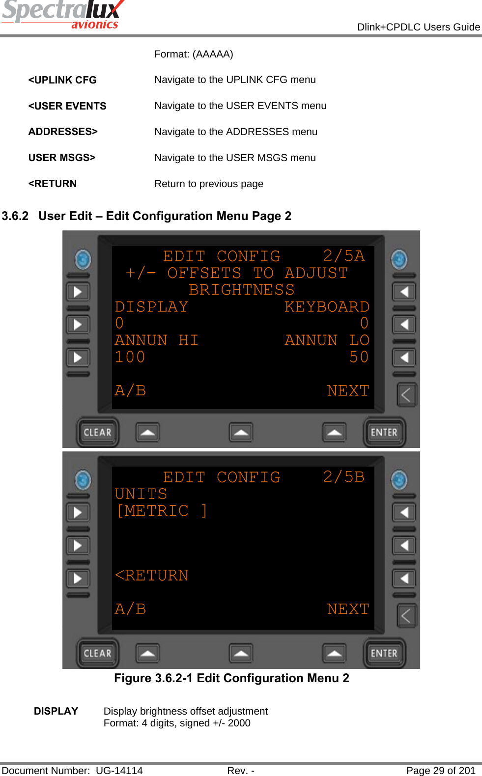
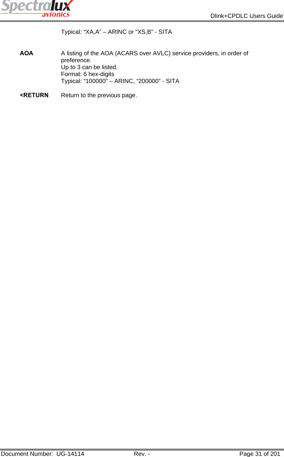
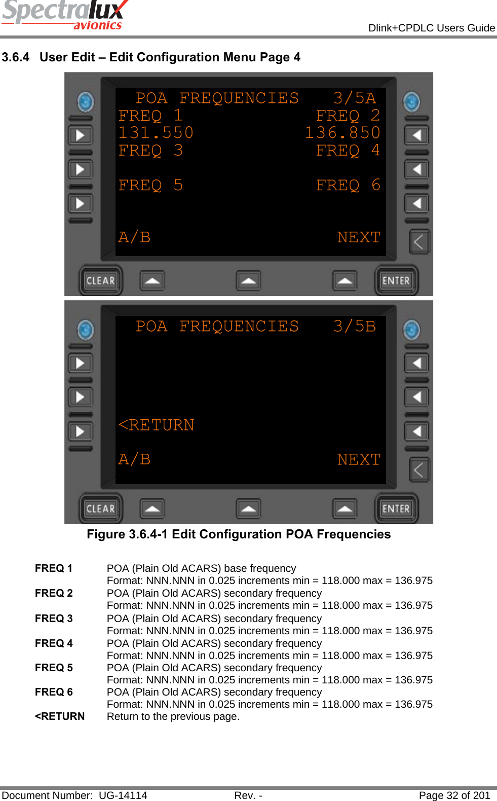
![Dlink+CPDLC Users Guide Document Number: UG-14114 Rev. - Page 30 of 201 KEYBOARD Keyboard brightness offset adjustment Format: 4 digits, signed +/- 2000 ANNUN HI Annunciator HI brightness offset adjustment Format:3 digits. 0-100 percent ANNUN LO Annunciator LO brightness offset adjustment Format:3 digits 0-100 percent UNITS Which format are units displayed in. Format: “ENGLISH”, “METRIC” <RETURN Return to the previous page. 3.6.3 User Edit – Edit Configuration Menu Page 3 Figure 3.6.3-1 Edit Configuration Menu 3 POA A listing of the POA (Plain Old ACARS) service providers, in order of preference. Up to 3 can be listed. Format: 4 characters (Service Provider [2 chars], “-“, Network type ( A or B )](https://usermanual.wiki/Spectralux/14114.Users-Manual-1/User-Guide-1874937-Page-30.png)


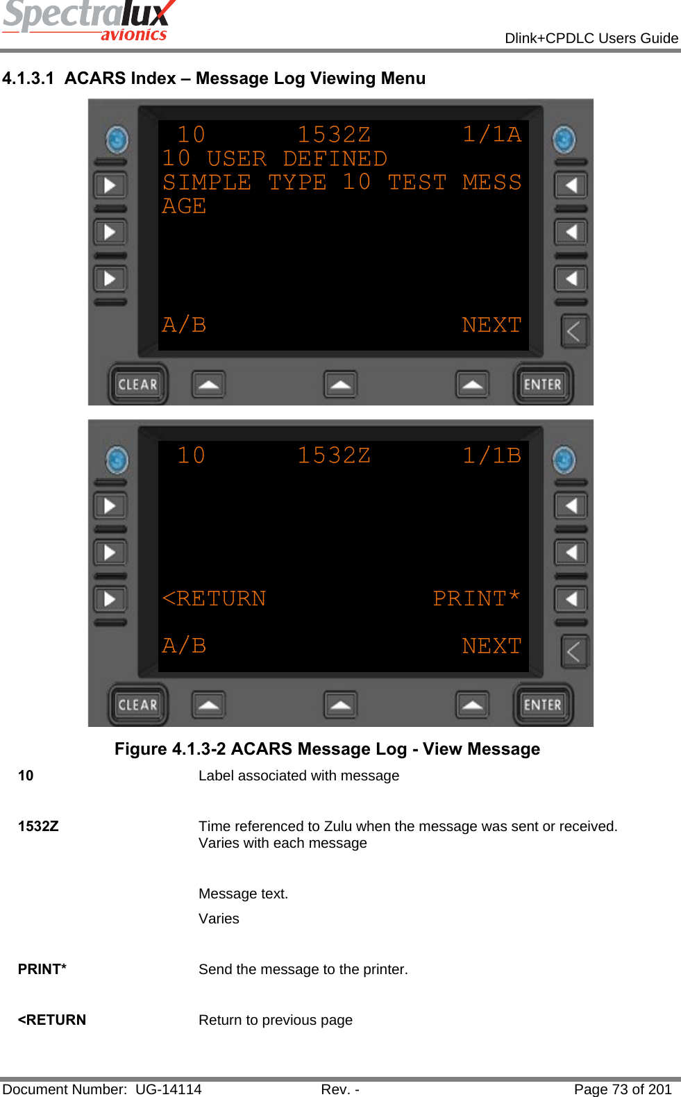
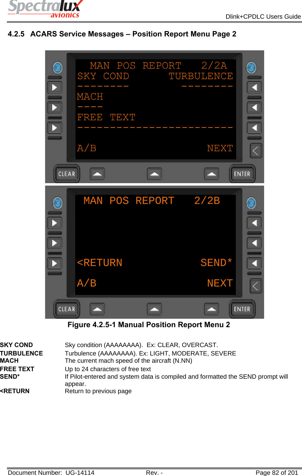
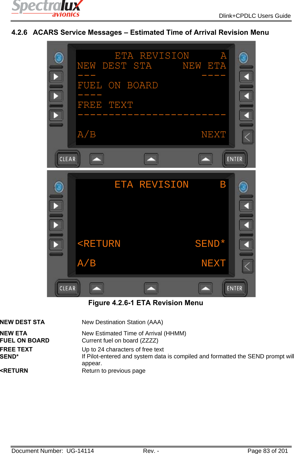
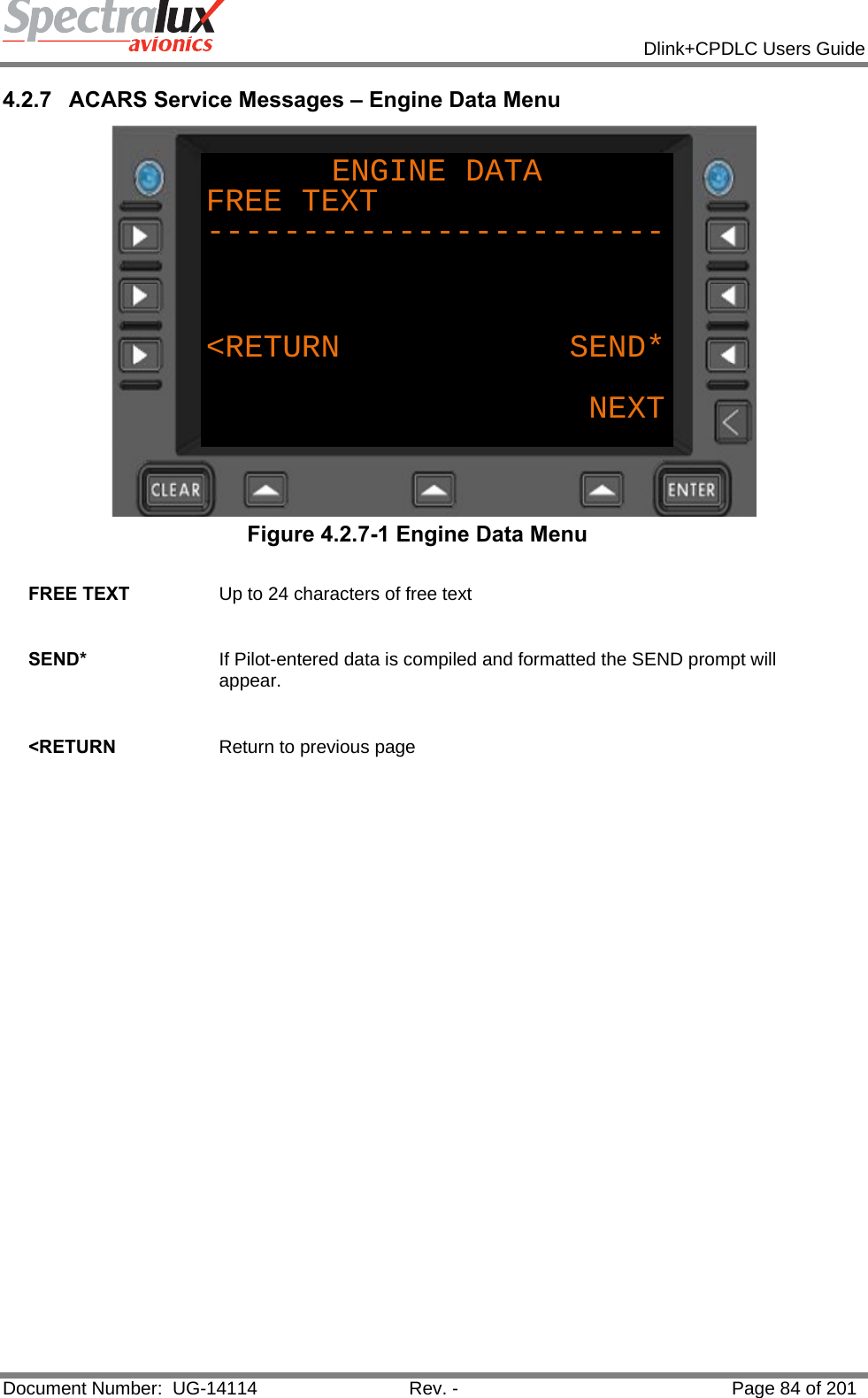
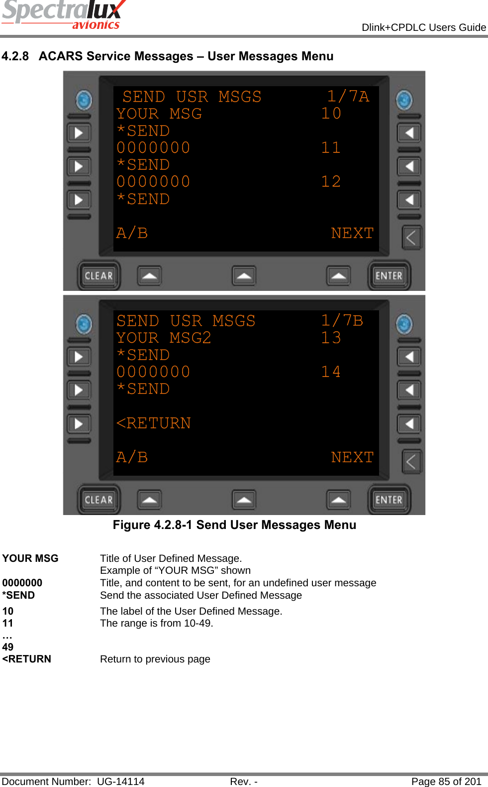
![Dlink+CPDLC Users Guide Document Number: UG-14114 Rev. - Page 81 of 201 4.2.4 ACARS Service Messages – Position Report Menu Page 1 Figure 4.2.4-1 Manual Position Report Menu 1 POSITION Current position. 1-5 alpha-numeric characters. May be a 3 character radio NAVID FLT LEVEL The current altitude. 3 digits zero-filled. Generally collected from 429 data. NXT POS Next position. 1-5 alpha-numeric characters. May be a 3 character radio NAVID TIME Current UTC (HHMM) TIME OVR Time estimated at Next Position ( HHMM) FUEL ON BOARD Current fuel on board (ZZZZ) SAT Static Air Temperature (SNN) Where: "S" is "+" or " –". "NN" represents a 2 digit Temperature in Celsius, zero filled. WIND DIR Wind Direction (NNN) zero filled [000-359] WIND SPD Wind Speed (NNN) zero filled [000-999] <RETURN Return to previous page](https://usermanual.wiki/Spectralux/14114.Users-Manual-1/User-Guide-1874937-Page-81.png)
![Dlink+CPDLC Users Guide Document Number: UG-14114 Rev. - Page 87 of 201 4.2.10 ACARS Service Messages – Service Message Setup Menu Figure 4.2.10-1 Service Message Report Setup Menu DEP/ARR REPORT This configuration item controls the automatic transmission of message Label Q1: "Departure/Arrival Report" in response to an OFF or IN Event. Select from: [AUTO] or [OFF ] <IATA Navigate to the IATA Service Message Setup Menu ICAO> Navigate to the ICAO Service Message Setup Menu <RETURN Return to previous page](https://usermanual.wiki/Spectralux/14114.Users-Manual-1/User-Guide-1874937-Page-87.png)
![Dlink+CPDLC Users Guide Document Number: UG-14114 Rev. - Page 88 of 201 4.2.11 ACARS Service Messages – IATA Report Setup Menu Page 1 Figure 4.2.11-1 IATA Report Setup Menu 1 OUT/FUEL REPORT Controls the automatic transmission of message Label QA: "Out/Fuel Report" in immediately following an OUT event. OFF REPORT Controls the automatic transmission of message Label QB: "Off Report" in immediately following an OFF event. ON REPORT Controls the automatic transmission of message Label QC: "On Report" in immediately following an ON event IN/FUEL REPORT Controls the automatic transmission of message Label QD: "In Fuel Report" in immediately following an IN event. OUT/FUEL/DEST Controls the automatic transmission of message Label QE: "Out/Fuel/Destination Report" in immediately following an OUT event. OFF/DEST REPORT Controls the automatic transmission of message Label QF: "Off/Destination Report" in immediately following an OFF event All Select from: “[AUTO]” or “[OFF ]”](https://usermanual.wiki/Spectralux/14114.Users-Manual-1/User-Guide-1874937-Page-88.png)
![Dlink+CPDLC Users Guide Document Number: UG-14114 Rev. - Page 89 of 201 4.2.12 ACARS Service Messages – IATA Report Setup Menu Page 2 Figure 4.2.12-1 IATA Report Setup Menu Page 2 OUT/RETURN IN REPORT Controls the automatic transmission of message Label QG: "Out/Return In Report" when an aircraft returns to the gate after an OUT event. OUT REPORT Controls the automatic transmission of message Label QH: "Out Report" immediately following an OUT event. LANDING REPORT Controls the automatic transmission of message Label QK: "Landing Report" immediately following an ON event. ARRIVAL REPORT Controls the automatic transmission of message Label QM: "Arrival INOFRMATION Report" immediately following an IN event. ARRIVAL INFO REPORT Controls the automatic transmission of a message label QM shall be sent when an "In Event" has occurred. <RETURN Return to previous page All Select from: “[AUTO]” or “[OFF ]”](https://usermanual.wiki/Spectralux/14114.Users-Manual-1/User-Guide-1874937-Page-89.png)
![Dlink+CPDLC Users Guide Document Number: UG-14114 Rev. - Page 90 of 201 4.2.13 ACARS Service Messages – ICAO Report Setup Menu ICAO REPORTS SETUP A OUT REPORT[AUTO]OFF REPORT[AUTO]ON REPORT[AUTO]A/B NEXT Figure 4.2.13-1 ACARS ICAO Reports Setup Menu OUT REPORT Controls the automatic transmission of message Label QP: "Out Report" immediately following an OUT event. OFF REPORT Controls the automatic transmission of message Label QQ: "Off Report" in immediately following an OFF event. ON REPORT Controls the automatic transmission of message Label QR: "On Report" in immediately following an ON event. IN REPORT Controls the automatic transmission of message Label QS: "In Report" in immediately following an IN event. OUT/RETURN IN REPORT Controls the automatic transmission of message Label QT: "Out/Return In Report" when an aircraft returns to the gate after an OUT event. <RETURN Return to previous page](https://usermanual.wiki/Spectralux/14114.Users-Manual-1/User-Guide-1874937-Page-90.png)
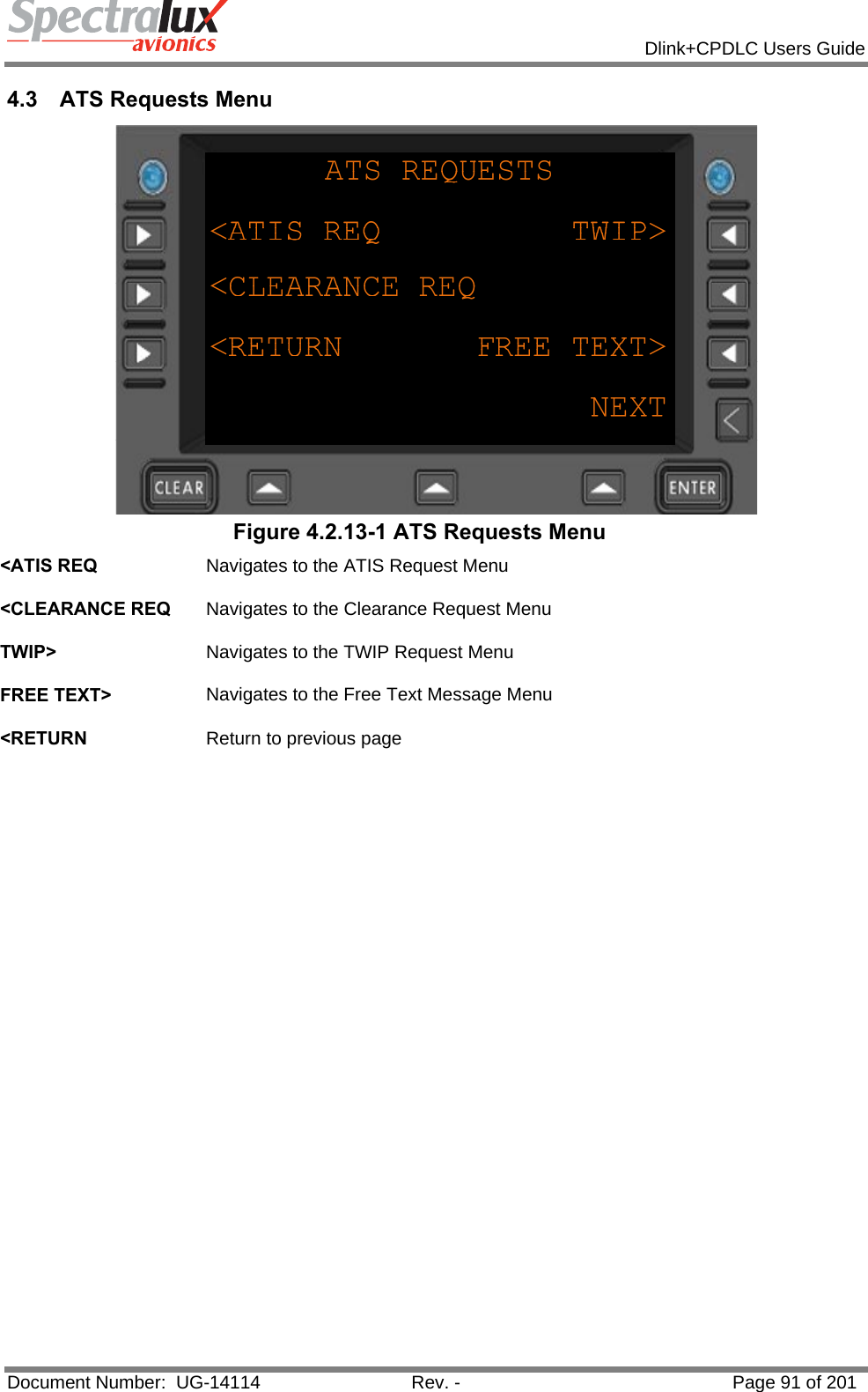
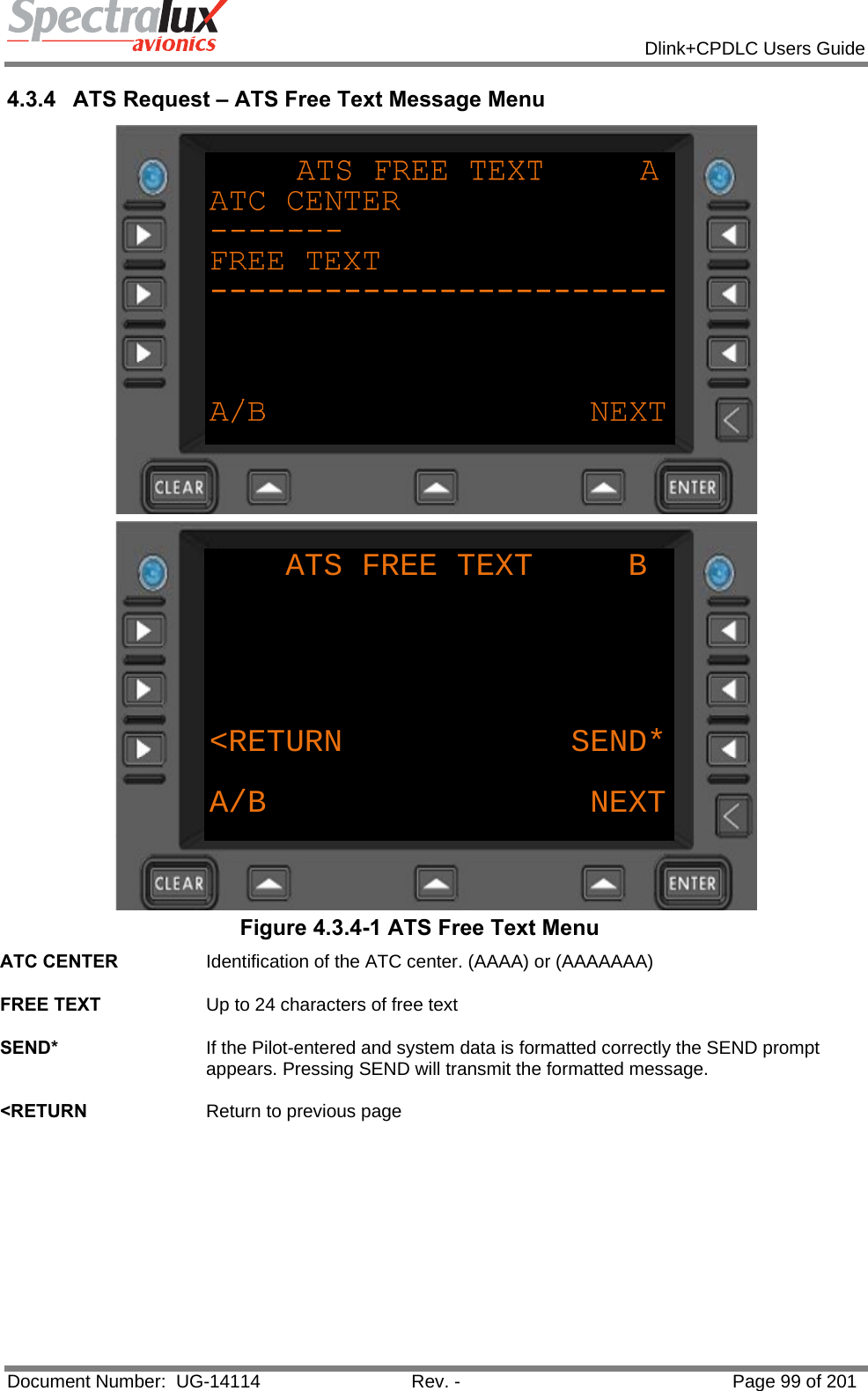
![Dlink+CPDLC Users Guide Document Number: UG-14114 Rev. - Page 92 of 201 4.3.1 ATS Request – ATIS Report Request Menu ATIS REPORT REQUESTARR/DEP IND AIRPORT[A] ----<RETURN SEND*NEXT Figure 4.3.1-1 ATIS Report Request Menu ARR/DEP IND The Arrival/Departure Indicator Selections: "A" is Arrival ATIS "D" is Departure ATIS "C" is Arrival ATIS with Automatic update "E" is Automatic Enroute Information Service (AEIS) or VOLMET "T" is Terminate automatic update of ATIS AIRPORT The Airport ID field. (AAAA) SEND* If Pilot-entered and system data is compiled and formatted the SEND prompt will appear. If pressed the formatted message is sent. <RETURN Return to previous page](https://usermanual.wiki/Spectralux/14114.Users-Manual-1/User-Guide-1874937-Page-92.png)
![Dlink+CPDLC Users Guide Document Number: UG-14114 Rev. - Page 98 of 201 4.3.3 ATS Request – Terminal Weather Information for Pilots Request Menu TWIP REQUESTTWIP CODE AIRPORT[N] ----<RETURN SEND*NEXT Figure 4.3.3-1 TWIP Request TWIP CODE Terminal Weather Information for Pilots. Selections: “N" is Single TWIP Report "C" is TWIP with Automatic update "T" is Terminate automatic update of TWIP AIRPORT Airport Identifier (AAAA) SEND* If the Pilot-entered and system data is formatted correctly the SEND prompt appears. Pressing SEND will transmit the formatted message. <RETURN Return to previous page](https://usermanual.wiki/Spectralux/14114.Users-Manual-1/User-Guide-1874937-Page-98.png)