SparkLAN Communications 0685R04070 Wireless 11g Compact USB Adapter User Manual

SparkLAN Communications, Inc. Wireless 11g Compact USB Adapter Users Manual

User Manual S Series
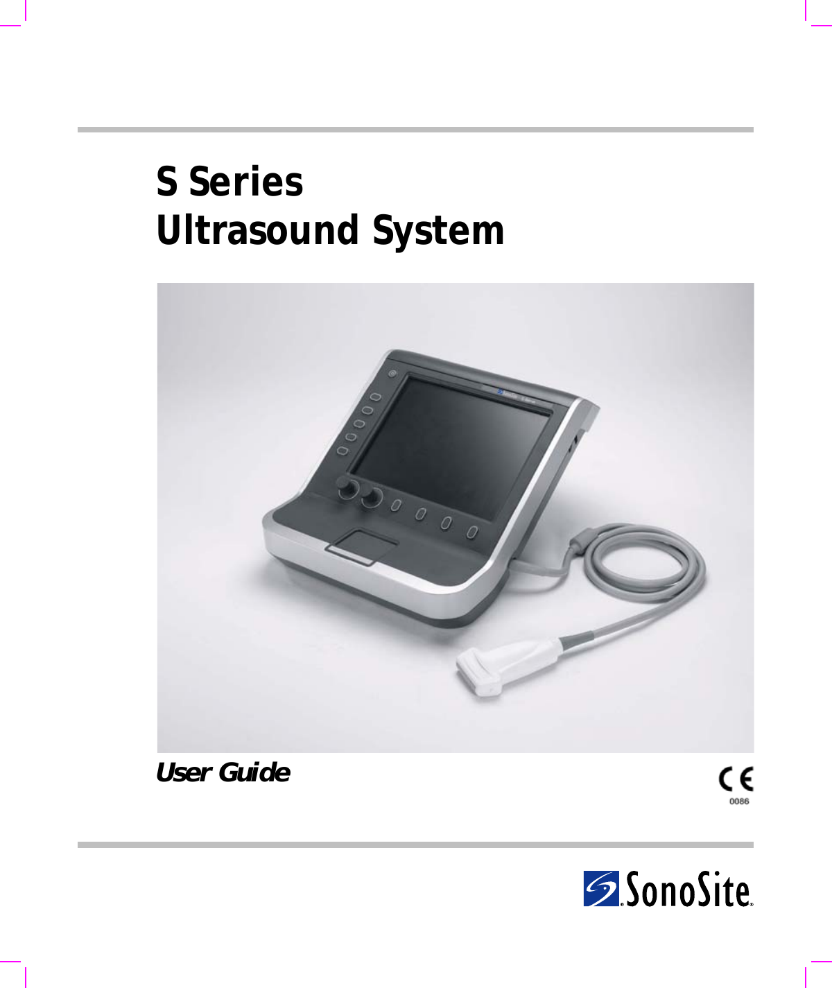
SSeriesUltrasound SystemUser Guide
S Series Ultrasound SystemUser Guide
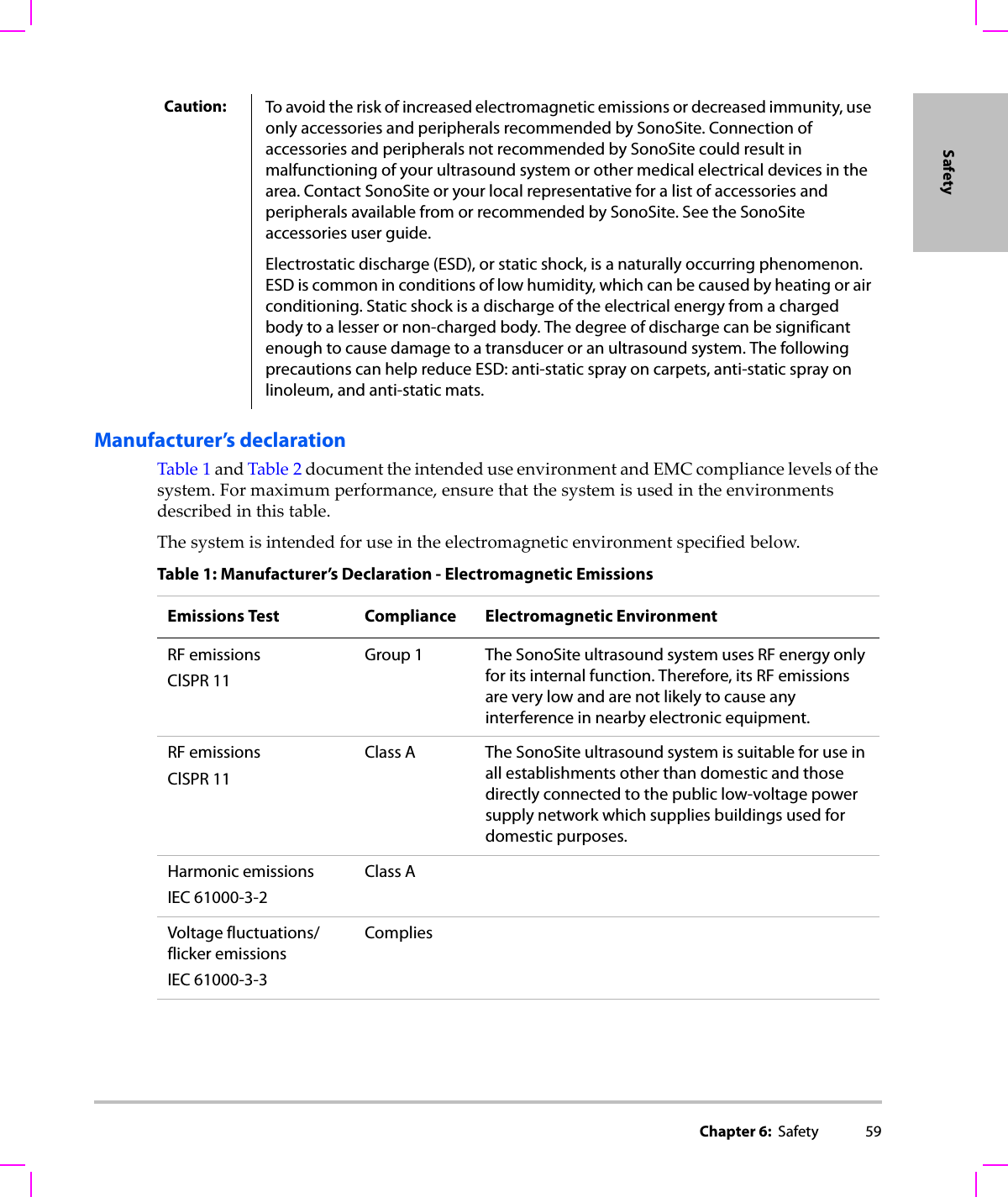
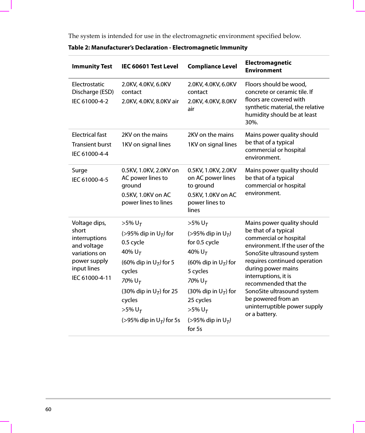
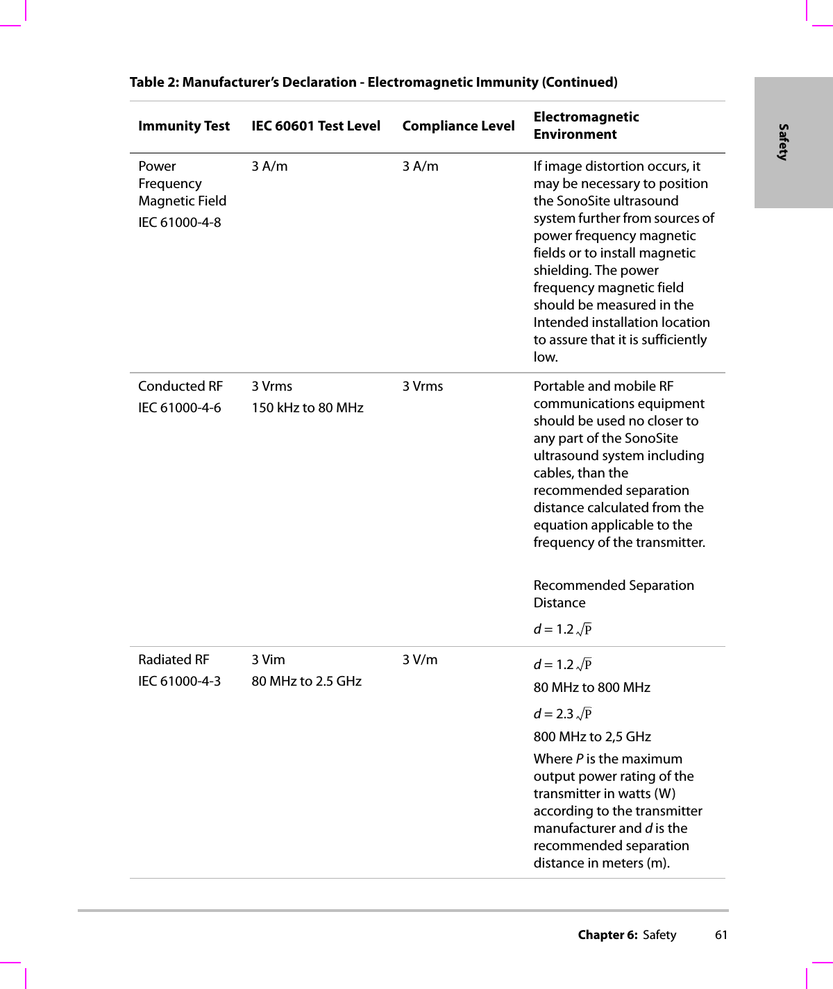
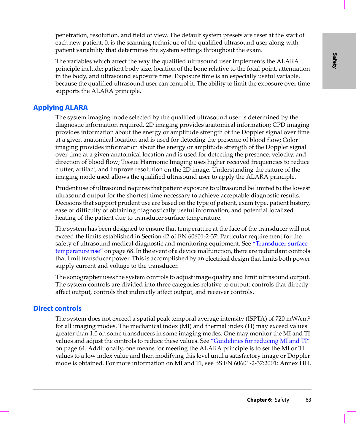
ii    SonoSite,Inc.2191930thDriveSEBothell,WA98021USAT:1‐888‐482‐9449or1‐425‐951‐1200F:1‐425‐951‐1201SonoSiteLtdAlexanderHouse40AWilburyWayHitchinHertsSG40APUKT:+44‐1462‐444800F:+44‐1462‐444801S-Cath, S-FAST, S-ICU, S-Nerve, SiteLink, SonoHD, SonoMB, and SonoSite are registered trademarks or trademarks of SonoSite, Inc.Non-SonoSite product names may be trademarks or registered trademarks of their respective owners. Protected by U.S. patents: 5722412, 5817024, 5893363, 6135961, 6364839, 6371918, 6383139, 6416475, 6471651, 6569101, 6648826, 6962566, 7169108. Patents pendingP07525‐01 11/2007Copyright2007bySonoSite,Inc.Allrightsreserved.Caution: Federal (United States) law restricts this device to sale by or on the order of a physician.
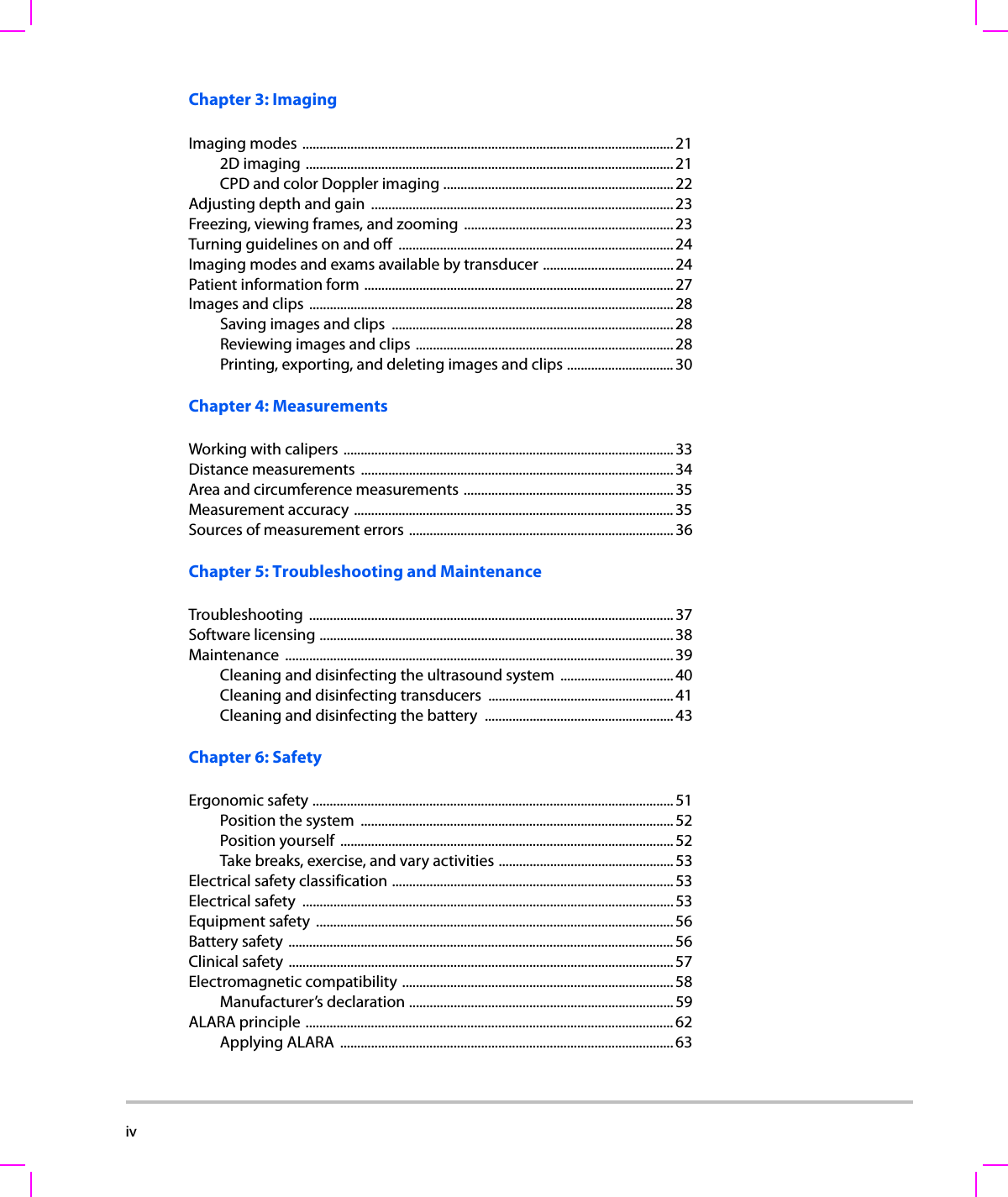
 iiiContentsIntroductionConventions .................................................................................................................. viiCustomer comments .................................................................................................. viiChapter 1: Getting StartedAbout the system  .......................................................................................................... 1Preparing the system  ................................................................................................... 1Compartments and connectors ...................................................................... 1Installing or removing the battery ................................................................. 3Using AC power and charging the battery  ................................................. 3Turning the system on or off ............................................................................ 4Connecting transducers  .................................................................................... 5Inserting and removing USB storage devices ............................................ 6System controls .............................................................................................................. 7Screen layout  ..................................................................................................................8General interaction ....................................................................................................... 9Touchpad ................................................................................................................ 9Control keys ............................................................................................................ 9Entering text  .......................................................................................................... 9Preparing transducers  ...............................................................................................10Intended uses  ...............................................................................................................11Chapter 2: System SetupDisplaying the setup pages  .....................................................................................13Restoring default settings ........................................................................................13Administration setup  .................................................................................................14Security settings  .................................................................................................14User setup  .............................................................................................................15Exporting or importing user accounts  .......................................................16Exporting and clearing the Event log  .........................................................16Logging in as user ..............................................................................................17Choosing a secure password  .........................................................................17Audio, Battery setup ...................................................................................................18Connectivity setup ......................................................................................................18Date and Time setup ..................................................................................................19Display Information setup ........................................................................................19Presets setup .................................................................................................................19System Information setup ........................................................................................20USB Devices setup .......................................................................................................20
iv    Chapter 3: ImagingImaging modes ............................................................................................................212D imaging ........................................................................................................... 21CPD and color Doppler imaging ...................................................................22Adjusting depth and gain  ........................................................................................ 23Freezing, viewing frames, and zooming  ............................................................. 23Turning guidelines on and off  ................................................................................24Imaging modes and exams available by transducer ...................................... 24Patient information form ..........................................................................................27Images and clips  ..........................................................................................................28Saving images and clips  .................................................................................. 28Reviewing images and clips ........................................................................... 28Printing, exporting, and deleting images and clips ............................... 30Chapter 4: MeasurementsWorking with calipers ................................................................................................ 33Distance measurements  ...........................................................................................34Area and circumference measurements .............................................................35Measurement accuracy .............................................................................................35Sources of measurement errors .............................................................................36Chapter 5: Troubleshooting and MaintenanceTroubleshooting .......................................................................................................... 37Software licensing ....................................................................................................... 38Maintenance .................................................................................................................39Cleaning and disinfecting the ultrasound system  ................................. 40Cleaning and disinfecting transducers  ......................................................41Cleaning and disinfecting the battery  .......................................................43Chapter 6: SafetyErgonomic safety .........................................................................................................51Position the system  ........................................................................................... 52Position yourself  ................................................................................................. 52Take breaks, exercise, and vary activities ...................................................53Electrical safety classification .................................................................................. 53Electrical safety  ............................................................................................................ 53Equipment safety  ........................................................................................................ 56Battery safety ................................................................................................................ 56Clinical safety ................................................................................................................57Electromagnetic compatibility ...............................................................................58Manufacturer’s declaration ............................................................................. 59ALARA principle ...........................................................................................................62Applying ALARA  ................................................................................................. 63
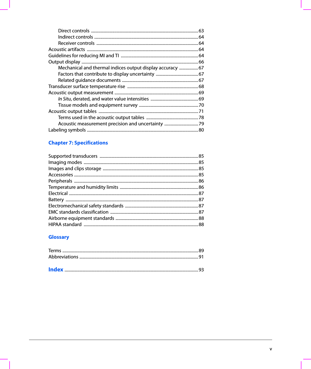
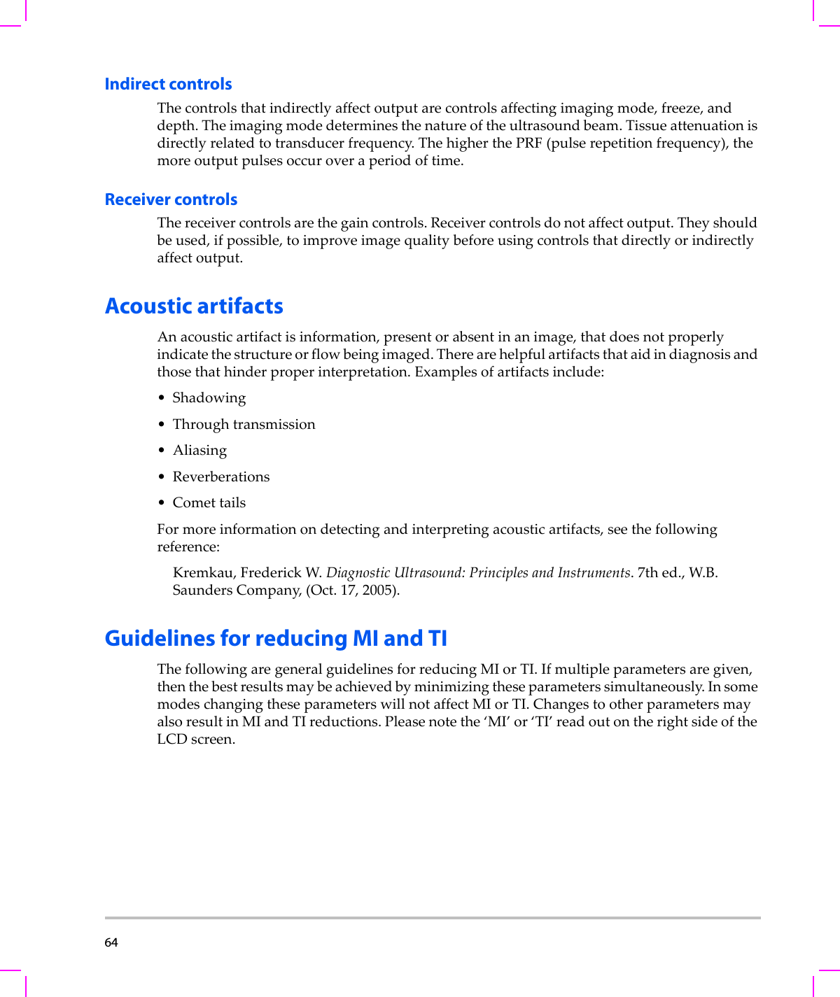
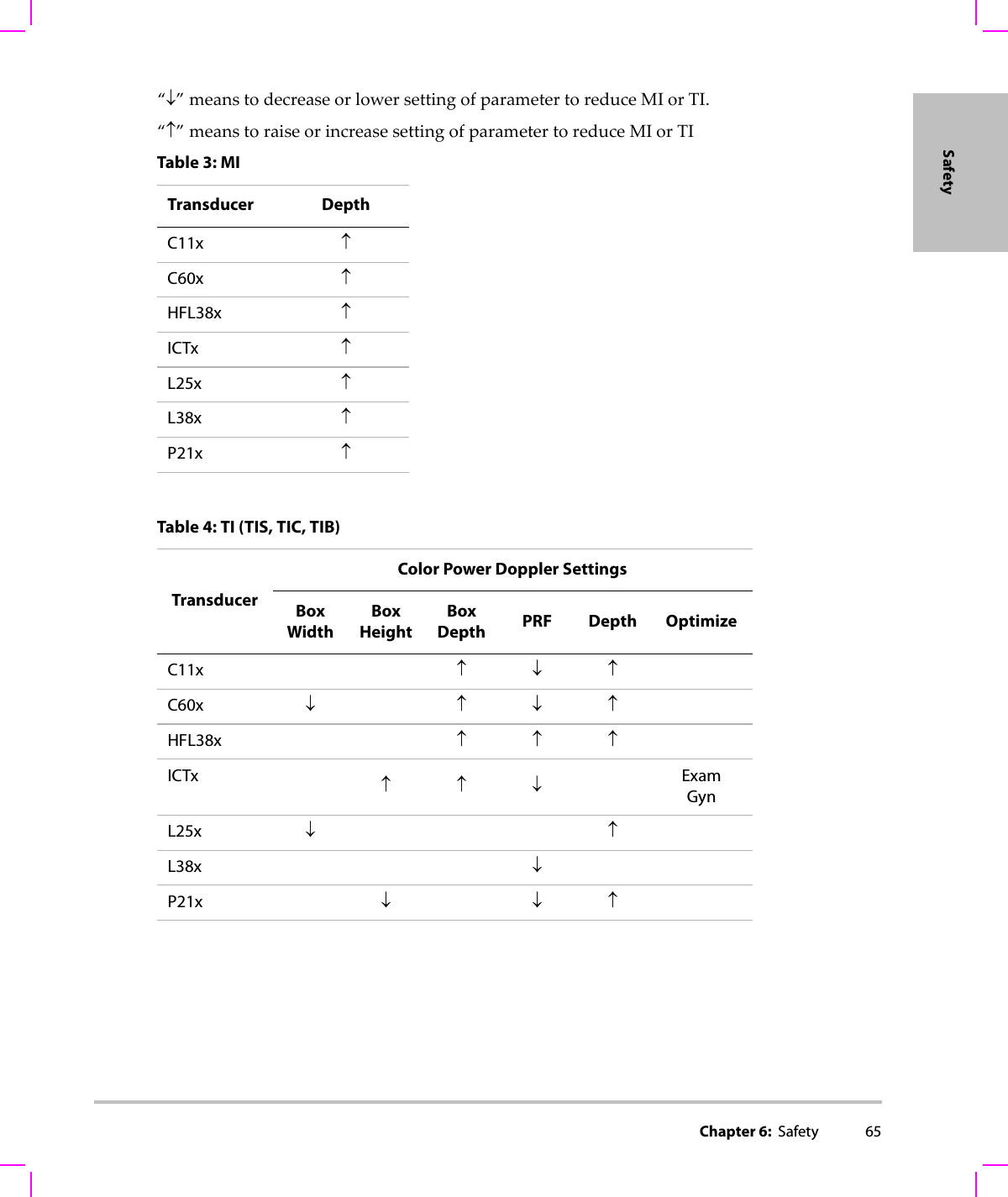
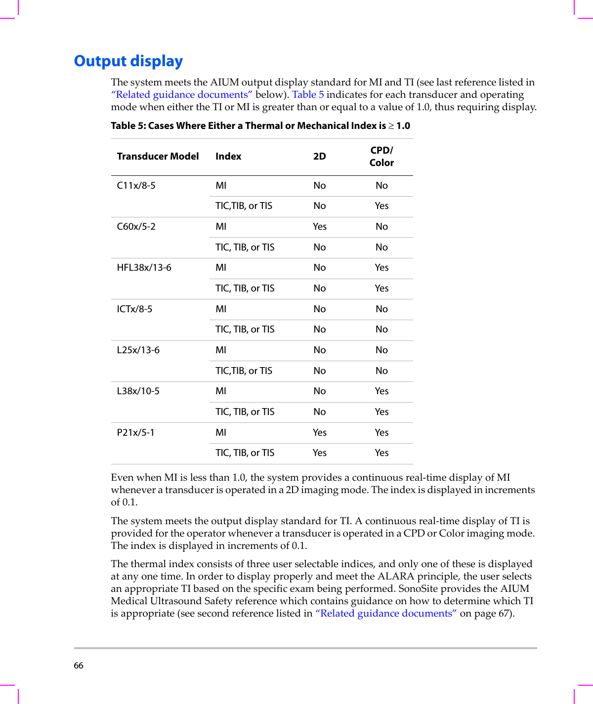
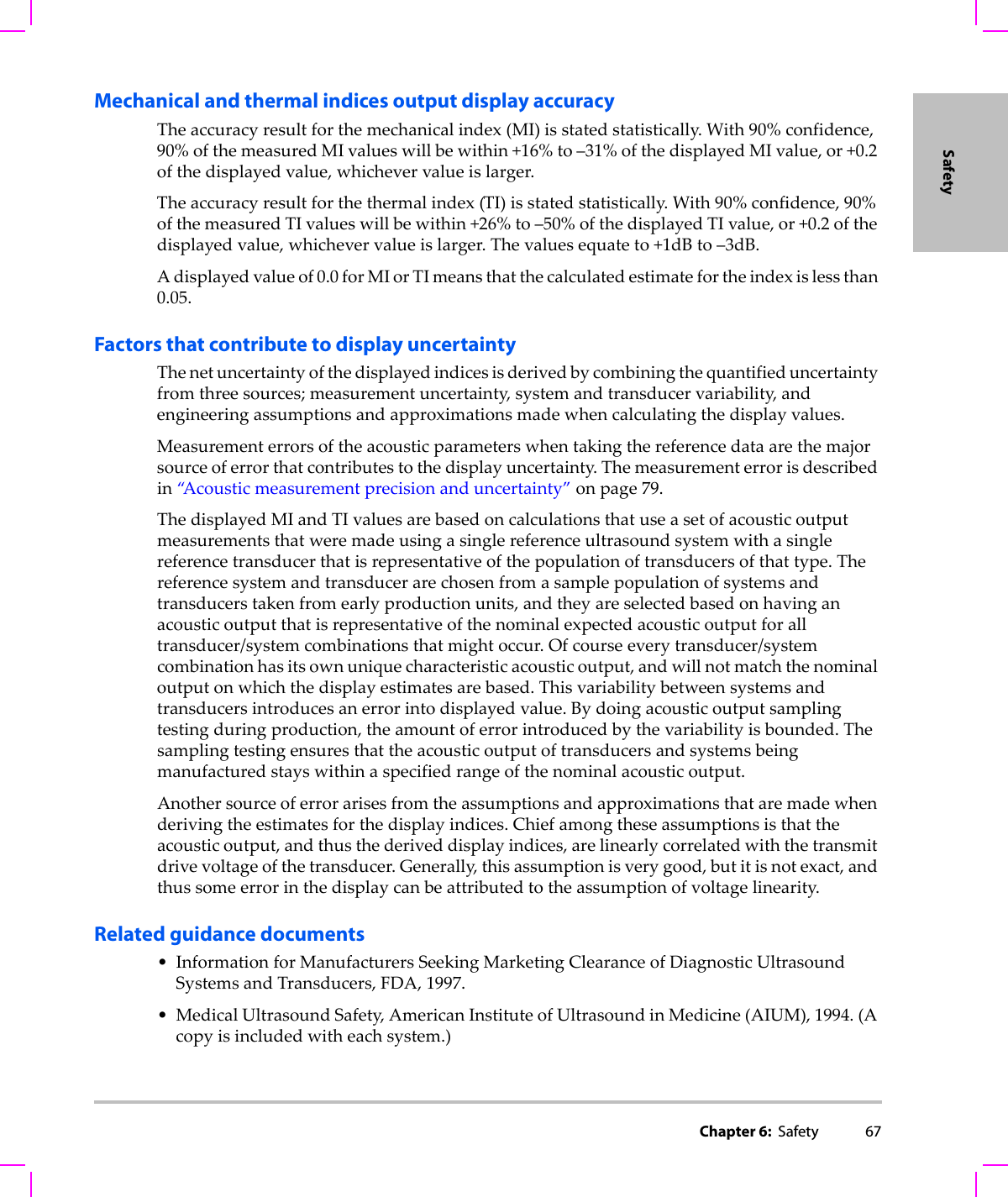
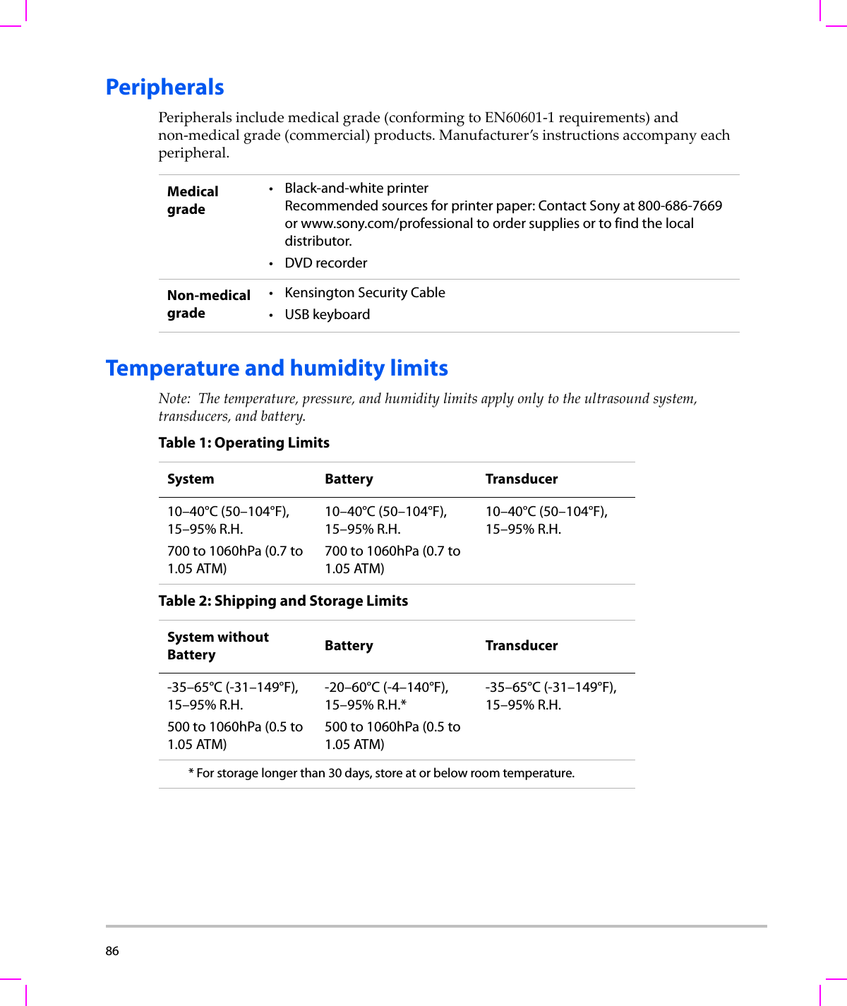
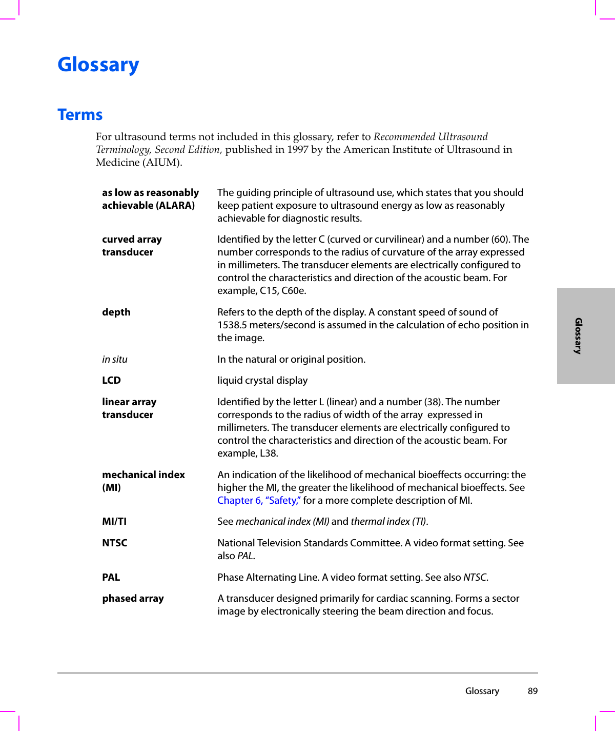
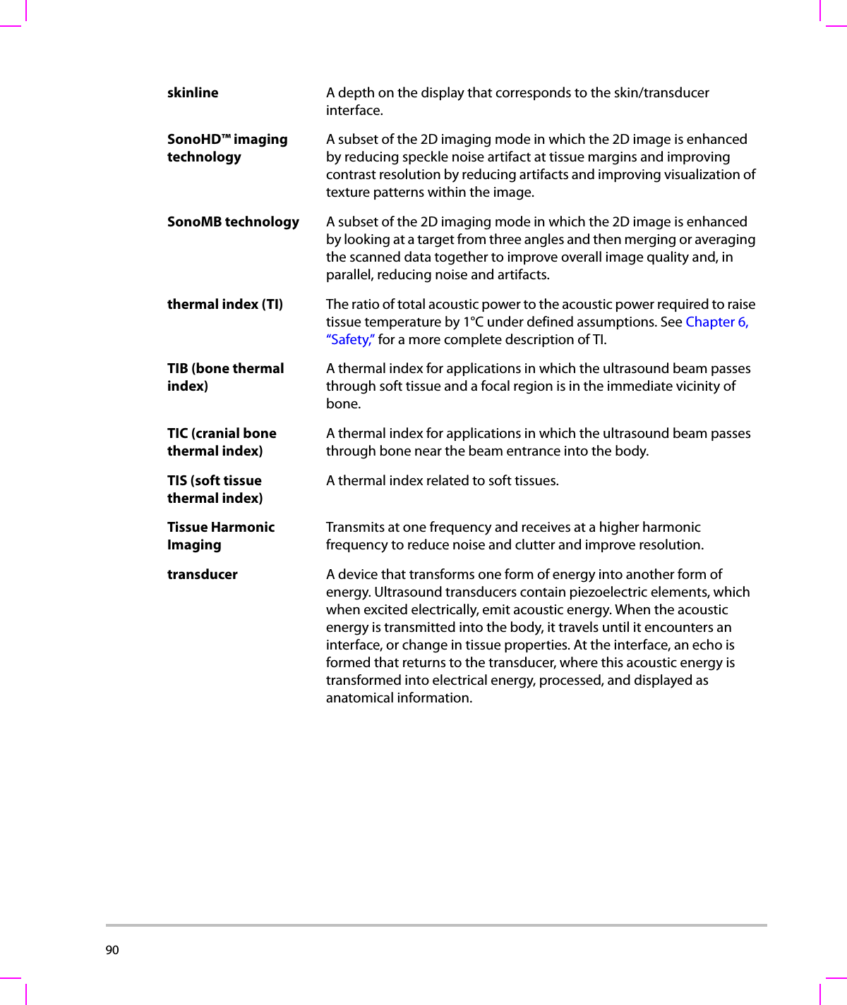
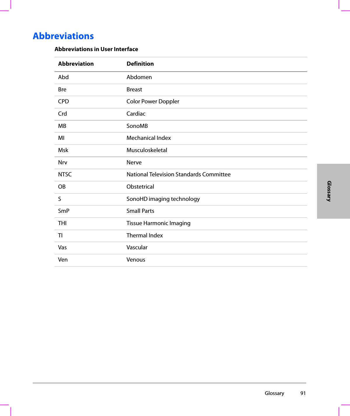
 vDirect controls .....................................................................................................63Indirect controls ..................................................................................................64Receiver controls  ................................................................................................64Acoustic artifacts  .........................................................................................................64Guidelines for reducing MI and TI  .........................................................................64Output display ..............................................................................................................66Mechanical and thermal indices output display accuracy ..................67Factors that contribute to display uncertainty ........................................67Related guidance documents ........................................................................67Transducer surface temperature rise  ...................................................................68Acoustic output measurement ...............................................................................69In Situ, derated, and water value intensities  .............................................69Tissue models and equipment survey ........................................................70Acoustic output tables  ..............................................................................................71Terms used in the acoustic output tables  .................................................78Acoustic measurement precision and uncertainty ................................79Labeling symbols .........................................................................................................80Chapter 7: SpecificationsSupported transducers  .............................................................................................85Imaging modes  ............................................................................................................85Images and clips storage ..........................................................................................85Accessories .....................................................................................................................85Peripherals .....................................................................................................................86Temperature and humidity limits ..........................................................................86Electrical ..........................................................................................................................87Battery .............................................................................................................................87Electromechanical safety standards .....................................................................87EMC standards classification ...................................................................................87Airborne equipment standards ..............................................................................88HIPAA standard  ............................................................................................................88GlossaryTerms ................................................................................................................................89Abbreviations ................................................................................................................91Index ..............................................................................................................................93
vi
 Introduction viiIntroductionIntroductionThisSSeriesUltrasoundSystemUserGuideprovidesinformationonpreparingandusingtheSSeriesultrasoundsystemandoncleaninganddisinfectingthesystemandtransducers.Italsoprovidessystemspecifications,andsafetyandacousticoutputinformation.Theuserguideisforareaderfamiliarwithultrasoundtechniques.Itdoesnotprovidetraininginsonographyorclinicalpractices.Beforeusingthesystem,youmusthaveultrasoundtraining.SeetheapplicableSonoSiteaccessoryuserguideforinformationonusingaccessoriesandperipherals.Seethemanufacturer’sinstructionsforspecificinformationaboutperipherals.ConventionsTheuserguidefollowstheseconventions:•AWARNINGdescribesprecautionsnecessarytopreventinjuryorlossoflife.•ACautiondescribesprecautionsnecessarytoprotecttheproducts.•Numberedstepsmustbeperformedinaspecificorder.•Bulletedlistspresentinformationinlistformatbutdonotimplyasequence.SymbolsandtermsusedonthesystemandtransducerareexplainedinChapter 1,Chapter 6,andGlossary.Customer commentsQuestionsandcommentsareencouraged.SonoSiteisinterestedinyourfeedbackregardingthesystemandtheuserguide.PleasecallSonoSiteat888‐482‐9449intheUS.OutsidetheUS,callthenearestSonoSiterepresentative.Youcanalsoe‐mailSonoSiteat comments@sonosite.com.
viii  Fortechnicalsupport,pleasecontactSonoSiteasfollows:SonoSite Technical SupportPhone (US or Canada): 877-657-8118Phone (Outside US and Canada):425-951-1330 Or call your local representative.Fax: 425-951-6700E-mail: service@sonosite.comWeb site: www.sonosite.com. Click Support & Service.Europe Service Center: +44-(0)1462-444-800e-mail: uk.service@sonosite.com
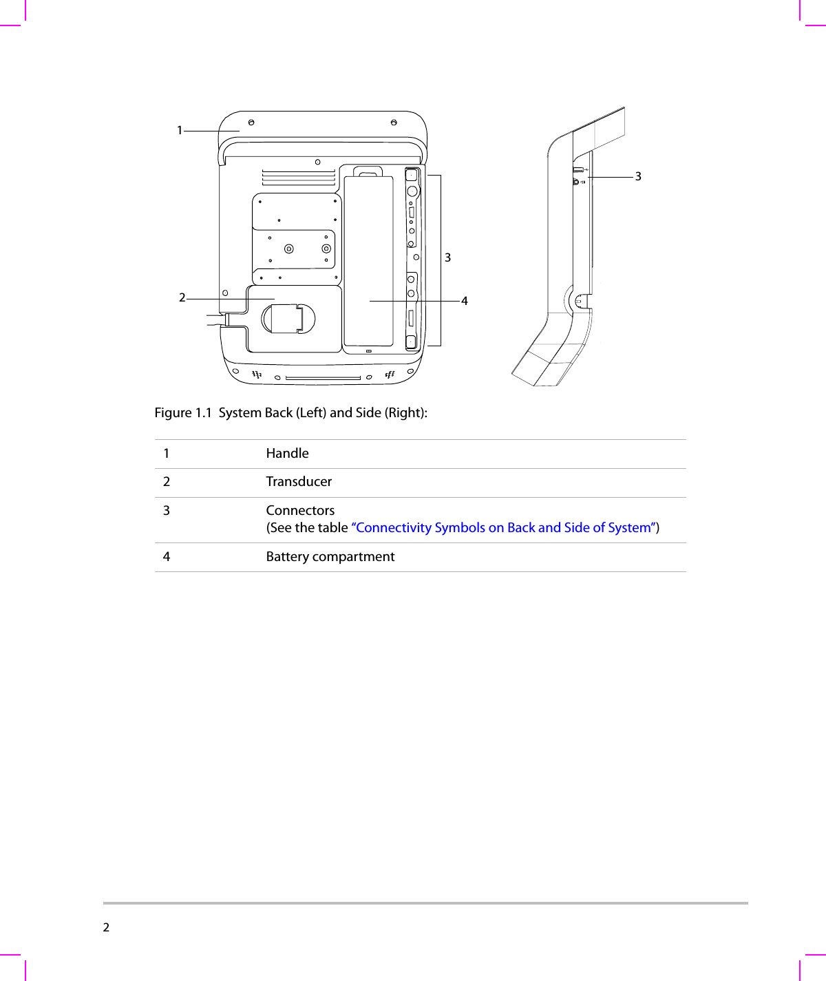
Chapter 1:  Getting Started 1Getting StartedChapter 1: Getting StartedAbout the systemTheSonoSiteSSeriesultrasoundsystemisaportable,software‐controlleddeviceusingall‐digitalarchitecture.TheSSeriesincludestheS‐Cath™ultrasoundsystem,S‐FAST™ultrasoundsystem,S‐ICU™ultrasoundsystem,andtheS‐Nerve™ultrasoundsystem.Thesystemhasmultipleconfigurationsandfeaturesetsusedtoacquireanddisplayhigh‐resolution,real‐timeultrasoundimages.Featuresavailableonyoursystemdependonsystemconfiguration,transducer,andexamtype.Alicensekeyisrequiredtoactivatethesoftware.See“Softwarelicensing”onpage 38.Onoccasion,asoftwareupgrademayberequired.SonoSiteprovidesaUSBdevicecontainingthesoftware.OneUSBdevicecanupgrademultiplesystems.To use the ultrasound system1Turnthesystemon.(Forpowerswitchlocation,see“Systemcontrols”onpage 7.)2Attachatransducer.3PressPatient,andcompletethepatientinformationform.4Pressanimaging‐modecontrolkey:2DorColor.Preparing the systemCompartments and connectorsThebackofthesystemhascompartmentsforthebatteryandtransduceraswellasconnectorsforUSBdevices,powercords,cables,andmore.Thesidehasadditionalconnectors.
2  Figure 1.1 System Back (Left) and Side (Right):1Handle2Transducer3 Connectors (See the table “Connectivity Symbols on Back and Side of System”)4 Battery compartment43213
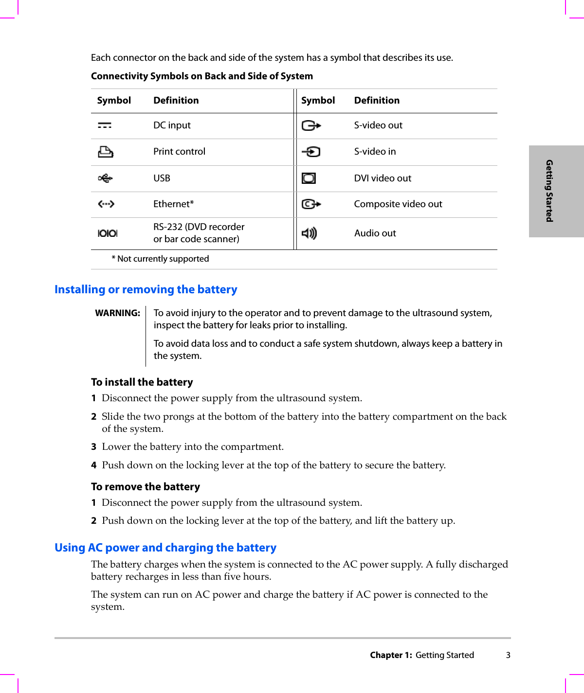
Chapter 1:  Getting Started 3Getting StartedEach connector on the back and side of the system has a symbol that describes its use.Installing or removing the batteryTo install the battery1Disconnectthepowersupplyfromtheultrasoundsystem.2Slidethetwoprongsatthebottomofthebatteryintothebatterycompartmentonthebackofthesystem.3Lowerthebatteryintothecompartment.4Pushdownonthelockingleveratthetopofthebatterytosecurethebattery.To remove the battery1Disconnectthepowersupplyfromtheultrasoundsystem.2Pushdownonthelockingleveratthetopofthebattery,andliftthebatteryup.Using AC power and charging the batteryThebatterychargeswhenthesystemisconnectedtotheACpowersupply.Afullydischargedbatteryrechargesinlessthanfivehours.ThesystemcanrunonACpowerandchargethebatteryifACpowerisconnectedtothesystem.Connectivity Symbols on Back and Side of SystemSymbol Definition Symbol DefinitionDC input S-video outPrint control S-video inUSB DVI video outEthernet* Composite video outRS-232 (DVD recorder or bar code scanner) Audio out* Not currently supportedWARNING: To avoid injury to the operator and to prevent damage to the ultrasound system, inspect the battery for leaks prior to installing.To avoid data loss and to conduct a safe system shutdown, always keep a battery in the system.
4  Thesystemcanrunonbatterypowerforuptotwohours,dependingontheimagingmodeandthedisplaybrightness.To operate the system using AC power1ConnecttheDCpowercablefromthepowersupplytotheconnectoronthesystem.SeeFigure 1.1onpage 2.2ConnecttheACpowercordtothepowersupplyandtoahospital‐gradeelectricaloutlet.Turning the system on or offTo turn the system on or offPressthepowerswitch.(See“Systemcontrols”onpage 7.)To wake up the systemToconservebatterylifewhilethesystemison,thesystemgoesintosleepmodeifuntouchedforapresettime.Toadjustthetimeforsleepdelay,see“A u d i o , Batterysetup”onpage 18.Pressakey,ortouchthetouchpad.WARNING: The equipment shall be connected to a center-tapped single phase supply circuit when users in the United States connect the equipment to a 240V supply system.Caution: Verify that the hospital supply voltage corresponds to the power supply voltage range. See “Electrical” on page 87.Caution: Do not use the system if an error message appears on the display. Note the error code and turn off the system. Call SonoSite or your local representative.
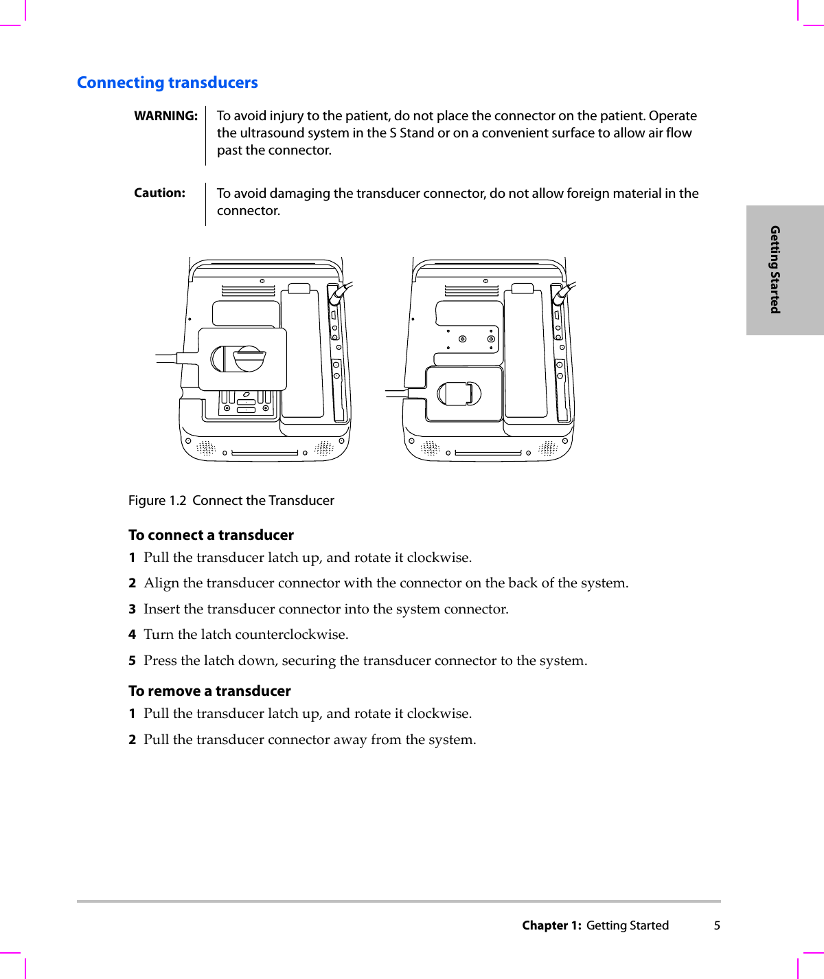
Chapter 1:  Getting Started 5Getting StartedConnecting transducersFigure 1.2 Connect the TransducerTo connect a transducer 1Pullthetransducerlatchup,androtateitclockwise.2Alignthetransducerconnectorwiththeconnectoronthebackofthesystem.3Insertthetransducerconnectorintothesystemconnector.4Turnthelatchcounterclockwise.5Pressthelatchdown,securingthetransducerconnectortothesystem.To remove a transducer1Pullthetransducerlatchup,androtateitclockwise.2Pullthetransducerconnectorawayfromthesystem.WARNING: To avoid injury to the patient, do not place the connector on the patient. Operate the ultrasound system in the S Stand or on a convenient surface to allow air flow past the connector.Caution: To avoid damaging the transducer connector, do not allow foreign material in the connector.
6  Inserting and removing USB storage devicesImagesandclipsaresavedtointernalstorageandareorganizedinasortablepatientlist.YoucanarchivetheimagesandclipsfromtheultrasoundsystemtoaPCusingaUSBstoragedevice.AlthoughtheimagesandclipscannotbeviewedfromaUSBstoragedeviceontheultrasoundsystem,youcanremovethedeviceandviewthemonyourPC.YoucanalsoimportandexportuseraccountsandtheeventlogusingaUSBstoragedevice.TherearethreeUSBportsonthesystem:twoontheback,andoneontheside.ForadditionalUSBports,youcanconnectaUSBhubintoanyUSBport.To insert a USB storage deviceInserttheUSBstoragedeviceintoaUSBportonthesystem.SeeFigure 1.1onpage 2.TheUSBstoragedeviceisreadywhentheUSBiconappears.Toviewinformationaboutthedevice,see“USBDevicessetup”onpage 20.To remove a USB storage deviceRemovingtheUSBstoragedevicewhilethesystemisexportingmaycausetheexportedfilestobecorruptedorincomplete.1WaitfivesecondsaftertheUSBanimationstops.2RemovetheUSBstoragedevicefromtheport.WARNING: To avoid damaging the USB storage device and losing patient data from it, observe the following:• Do not remove the USB storage device or turn off the ultrasound system while the system is exporting.• Do not bump or otherwise apply pressure to the USB storage device while it is in a USB port on the ultrasound system. The connector could break. Caution: If the USB icon does not appear in the system status area on-screen, the USB storage device may be defective or password-protected. Turn the system off and replace the device.
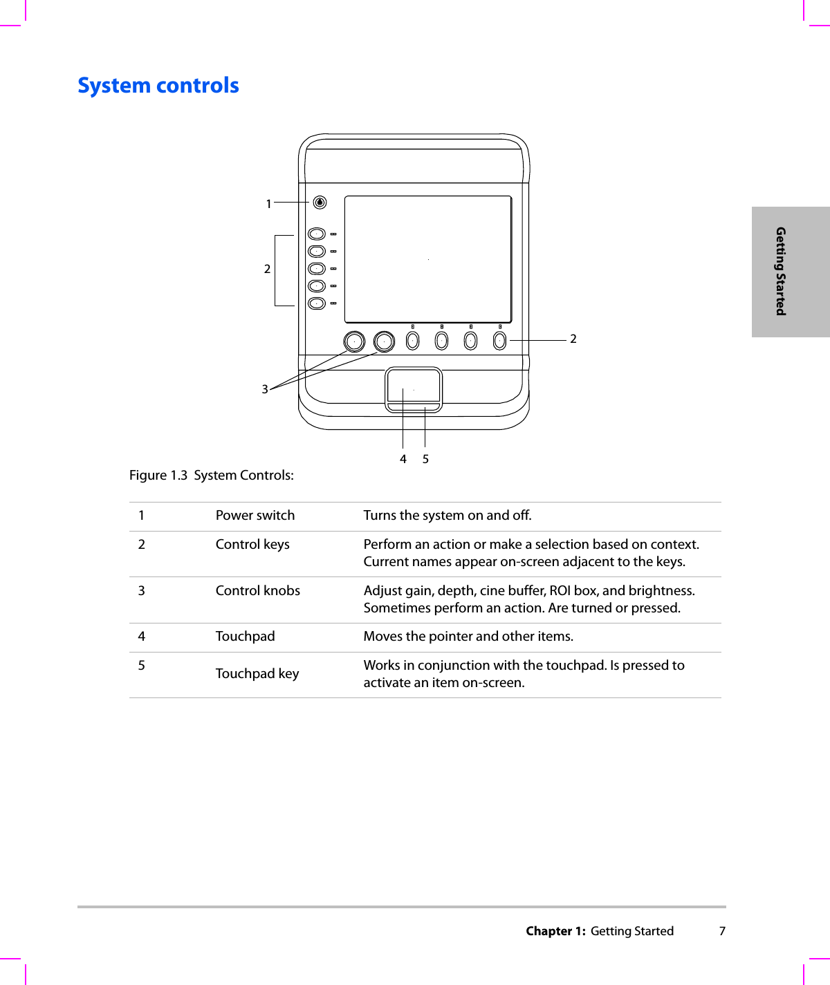
Chapter 1:  Getting Started 7Getting StartedSystem controlsFigure 1.3 System Controls:2324511 Power switch Turns the system on and off.2 Control keys Perform an action or make a selection based on context. Current names appear on-screen adjacent to the keys.3 Control knobs Adjust gain, depth, cine buffer, ROI box, and brightness. Sometimes perform an action. Are turned or pressed.4 Touchpad Moves the pointer and other items.5Touchpad key Works in conjunction with the touchpad. Is pressed to activate an item on-screen.
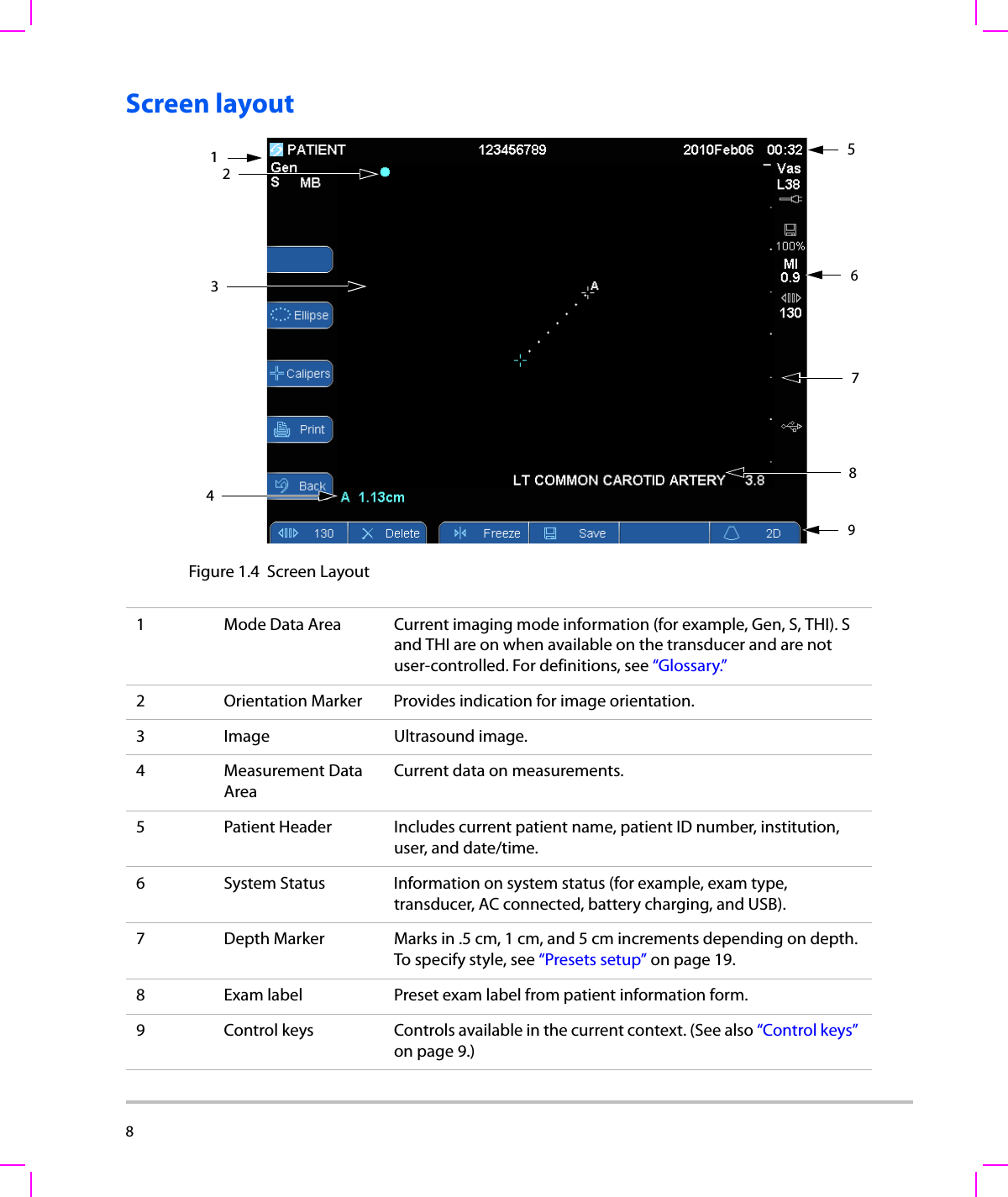
8  Screen layoutFigure 1.4 Screen Layout 3765418291 Mode Data Area Current imaging mode information (for example, Gen, S, THI). S and THI are on when available on the transducer and are not user-controlled. For definitions, see “Glossary.”2 Orientation Marker Provides indication for image orientation.3 Image Ultrasound image.4Measurement Data AreaCurrent data on measurements.5 Patient Header Includes current patient name, patient ID number, institution, user, and date/time.6 System Status Information on system status (for example, exam type, transducer, AC connected, battery charging, and USB).7 Depth Marker Marks in .5 cm, 1 cm, and 5 cm increments depending on depth. To specify style, see “Presets setup” on page 19.8 Exam label Preset exam label from patient information form.9 Control keys Controls available in the current context. (See also “Control keys” on page 9.)
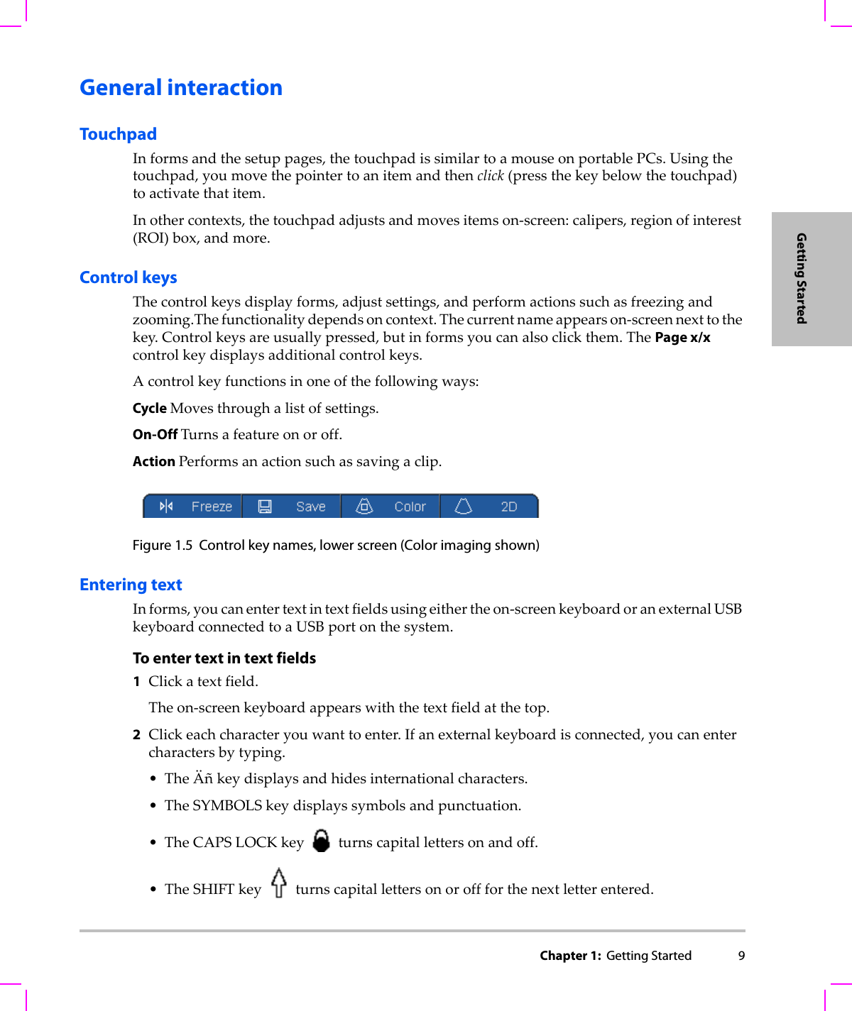
Chapter 1:  Getting Started 9Getting StartedGeneral interactionTouchpadInformsandthesetuppages,thetouchpadissimilartoamouseonportablePCs.Usingthetouchpad,youmovethepointertoanitemandthenclick(pressthekeybelowthetouchpad)toactivatethatitem.Inothercontexts,thetouchpadadjustsandmovesitemson‐screen:calipers,regionofinterest(ROI)box,andmore.Control keysThecontrolkeysdisplayforms,adjustsettings,andperformactionssuchasfreezingandzooming.Thefunctionalitydependsoncontext.Thecurrentnameappearson‐screennexttothekey.Controlkeysareusuallypressed,butinformsyoucanalsoclickthem.ThePage x/xcontrolkeydisplaysadditionalcontrolkeys.Acontrolkeyfunctionsinoneofthefollowingways:Cycle Movesthroughalistofsettings.On-Off Turnsafeatureonoroff.Action Performsanactionsuchassavingaclip.Figure 1.5 Control key names, lower screen (Color imaging shown)Entering textInforms,youcanentertextintextfieldsusingeithertheon‐screenkeyboardoranexternalUSBkeyboardconnectedtoaUSBportonthesystem.To enter text in text fields1Clickatextfield.Theon‐screenkeyboardappearswiththetextfieldatthetop.2Clickeachcharacteryouwanttoenter.Ifanexternalkeyboardisconnected,youcanentercharactersbytyping.•TheÄñkeydisplaysandhidesinternationalcharacters.•TheSYMBOLSkeydisplayssymbolsandpunctuation.•TheCAPSLOCKkeyturnscapitallettersonandoff.•TheSHIFTkeyturnscapitallettersonoroffforthenextletterentered.
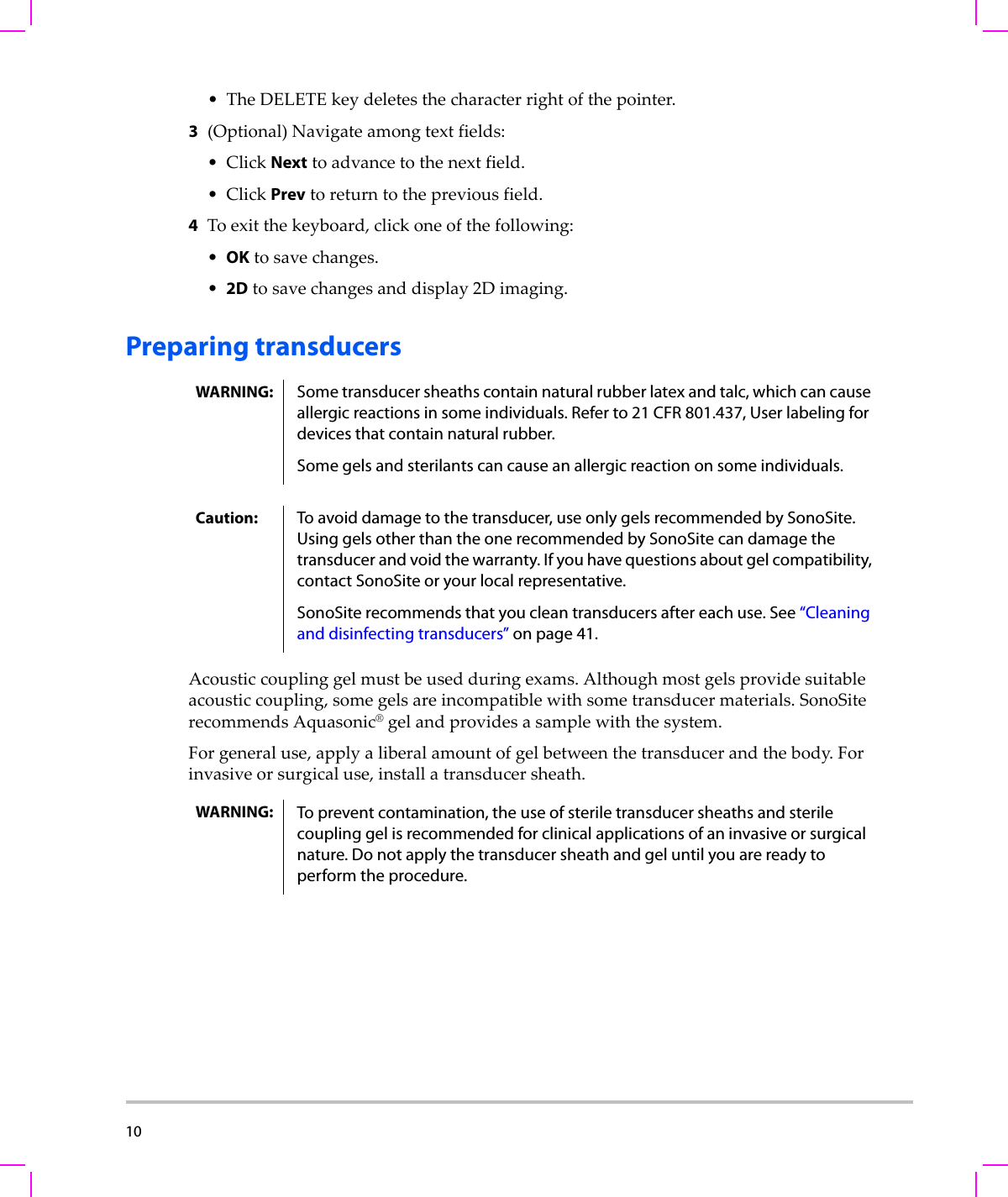
10  •TheDELETEkeydeletesthecharacterrightofthepointer.3(Optional)Navigateamongtextfields:•ClickNexttoadvancetothenextfield.•ClickPrevtoreturntothepreviousfield.4Toexitthekeyboard,clickoneofthefollowing:•OKtosavechanges.•2Dtosavechangesanddisplay2Dimaging.Preparing transducersAcousticcouplinggelmustbeusedduringexams.Althoughmostgelsprovidesuitableacousticcoupling,somegelsareincompatiblewithsometransducermaterials.SonoSiterecommendsAquasonic®gelandprovidesasamplewiththesystem.Forgeneraluse,applyaliberalamountofgelbetweenthetransducerandthebody.Forinvasiveorsurgicaluse,installatransducersheath.WARNING: Some transducer sheaths contain natural rubber latex and talc, which can cause allergic reactions in some individuals. Refer to 21 CFR 801.437, User labeling for devices that contain natural rubber.Some gels and sterilants can cause an allergic reaction on some individuals.Caution: To avoid damage to the transducer, use only gels recommended by SonoSite. Using gels other than the one recommended by SonoSite can damage the transducer and void the warranty. If you have questions about gel compatibility, contact SonoSite or your local representative.SonoSite recommends that you clean transducers after each use. See “Cleaning and disinfecting transducers” on page 41. WARNING: To prevent contamination, the use of sterile transducer sheaths and sterile coupling gel is recommended for clinical applications of an invasive or surgical nature. Do not apply the transducer sheath and gel until you are ready to perform the procedure.
Chapter 1:  Getting Started 11Getting StartedTo install a transducer sheathSonoSiterecommendstheuseofmarket‐cleared,transducersheathsforintracavitaryorsurgicalapplications.Tolessentheriskofcontamination,installthesheathonlywhenyouarereadytoperformtheprocedure.1Placegelinsidethesheath.2Insertthetransducerintothesheath.3Pullthesheathoverthetransducerandcableuntilthesheathisfullyextended.4Securethesheathusingthebandssuppliedwiththesheath.5Checkforandeliminatebubblesbetweenthefaceofthetransducerandthesheath.Bubblesbetweenthefaceofthetransducerandthesheathmayaffecttheultrasoundimage.6Inspectthesheathtoensurethattherearenoholesortears.Intended usesTheintendedusesforeachexamtypeareasfollows.Fortheintendedtransducerforeachexamtype,see“Imagingmodesandexamsavailablebytransducer”onpage 24.Abdominal Imaging Applications Thissystemtransmitsultrasoundenergyintotheabdomenofpatientsusing2D,SonoMB™technology,colorDoppler(Color),colorpowerDoppler(CPD),andTissueHarmonicImaging(THI)toobtainultrasoundimages.Theliver,kidneys,pancreas,spleen,gallbladder,bileducts,transplantedorgans,abdominalvessels,andsurroundinganatomicalstructurescanbeassessedforthepresenceorabsenceofpathologytransabdominally.Cardiac Imaging Applications Thissystemtransmitsultrasoundenergyintothethoraxofpatientsusing2D,SonoMBtechnology,colorDoppler(Color),andTissueHarmonicImaging(THI),toobtainultrasoundimages.Theheart,cardiacvalves,greatvessels,surroundinganatomicalstructures,overallcardiacperformance,andheartsizecanbeassessedforthepresenceorabsenceofpathology.Gynecology and Infertility Imaging Applications Thissystemtransmitsultrasoundenergyinthepelvisandlowerabdomenusing2D,SonoMBtechnology,colorpowerDoppler(CPD),andcolorDoppler(Color)toobtainultrasoundimages.Theuterus,ovaries,adnexa,andsurroundinganatomicalstructurescanbeassessedforthepresenceorabsenceofpathologytransabdominallyortransvaginally.Interventional Imaging Applications Thissystemtransmitsultrasoundenergyintothevariouspartsofthebodyusing2D,SonoMBtechnology,colorDoppler(Color),colorpowerDoppler(CPD),andTissueHarmonicImaging(THI)toobtainultrasoundimagesthatprovideguidanceduringinterventionalprocedures.Thissystemcanbeusedtoprovideultrasoundguidanceforbiopsyanddrainageprocedures,vascularlineplacement,peripheralnerveblocks,spinalnerveblocksandtaps,amniocentesisandotherobstetricalprocedures,andprovideassistanceduringabdominal,breast,andneurologicalsurgery.
12  Obstetrical Imaging Applications Thissystemtransmitsultrasoundenergyintothepelvisofpregnantwomenusing2D,SonoMBtechnology,colorDoppler(Color),andcolorpowerDoppler(CPD)toobtainultrasoundimages.Thefetalanatomy,amnioticfluid,andsurroundinganatomicalstructurescanbeassessedforthepresenceorabsenceofpathologytransvaginally.CPDandcolorDoppler(Color)imagingisintendedforhigh‐riskpregnantwomen.Pediatric Imaging Applications Thissystemtransmitsultrasoundenergyintothepediatricpatientsusing2D,SonoMBmulti‐beamtechnology,colorDoppler(Color),andcolorpowerDoppler(CPD)toobtainultrasoundimages.Thepediatricabdominalandpelvicanatomy,pediatrichips,andsurroundinganatomicalstructurescanbeassessedforthepresenceorabsenceofpathology.Superficial Imaging Applications Thissystemtransmitsultrasoundenergyintovariouspartsofthebodyusing2D,SonoMBmulti‐beamtechnology,colorDoppler(Color),andcolorpowerDoppler(CPD)toobtainultrasoundimages.Thebreast,thyroid,testicle,lymphnodes,hernias,musculoskeletalstructures,softtissuestructures,andsurroundinganatomicalstructurescanbeassessedforthepresenceorabsenceofpathology.Thissystemcanbeusedtoprovideultrasoundguidanceforbiopsyanddrainageprocedures,vascularlineplacement,peripheralnerveblocks,andspinalnerveblocksandtaps.Vascular Imaging Applications Thissystemtransmitsultrasoundenergyintothevariouspartsofthebodyusing2D,SonoMB,colorDoppler(Color),andcolorpowerDoppler(CPD)toobtainultrasoundimages.Thecarotidarteries,deepveins,andarteriesinthearmsandlegs,superficialveinsinthearmsandlegs,greatvesselsintheabdomen,andvarioussmallvesselsfeedingorganscanbeassessedforthepresenceorabsenceofpathology.WARNING: To prevent injury or misdiagnosis do not use this system for Percutaneous Umbilical Blood Sampling (PUBS) or in vitro Fertilization (IVF) The system has not been validated to be proven effective for these two uses.CPD or Color images can be used as an adjunctive method, not as a screening tool, for the detection of structural anomalies of the fetal heart and as an adjunctive method, not as a screening tool for the diagnosis of Intrauterine Growth Retardation (IUGR).
Chapter 2:  System Setup 13System SetupChapter 2: System SetupThesetuppagesletyoucustomizethesystemandsetpreferences.Displaying the setup pagesTo display a setup page1In2Dimagingmode,dooneofthefollowing:•PressPatient,andthenpressSetuponthehorizontalrowofcontrolkeys.•PressSetupontheverticalrowofcontrolkeys.2ClickthesetuppageunderSetup Pages.Toreturntoimagingfromasetuppage,pressDone.Restoring default settingsTo restore default settings for a setup pageOnthesetuppage,press Reset.To restore all default settings1Turnthesystemoff.2ConnectthesystemtoACpower.(See“TooperatethesystemusingACpower”onpage 4.)3Simultaneouslypressthepowerkeyandthecontrolkeybelowit(theupper‐leftcontrolkey).Thesystembeepsseveraltimes.
14  Administration setupOntheAdministrationsetuppage,youcanconfigurethesystemtorequireuserstologinandenterpasswords.Requiredloginhelpsprotectpatientdata.Youcanalsoaddanddeleteusers,changepasswords,importandexportuseraccounts,andviewtheeventlog.Security settingsSecuritysettingsonthesystemallowyoutomeettheapplicablesecurityrequirementslistedintheHIPAAstandard.Usersareultimatelyresponsibleforensuringthesecurityandprotectionofallelectronicprotectedhealthinformationcollected,stored,reviewed,andtransmittedonthesystem.To log in as Administrator1OntheAdministrationsetuppage,typeAdministratorintheNamebox.(See“Enteringtext”onpage 9.)2TypetheadministratorpasswordinthePasswordbox.Ifyoudon’thavetheadministratorpassword,contactSonoSite.(See“SonoSiteTechnicalSupport”onpage viii.)3ClickLogin.To log out as AdministratorTurnofforrestartthesystem.To require user loginYoucansetthesystemtodisplaytheUserLoginscreenatstartup.1LoginasAdministrator.2IntheUser Loginlist,clickOn.•Onrequiresausernameandpasswordatstartup.•Offallowsaccesstothesystemwithoutausernameandpassword.WARNING: Health care providers who maintain or transmit health information are required by the Health Insurance Portability and Accountability Act (HIPAA) of 1996 and the European Union Data Protection Directive (95/46/EC) to implement appropriate procedures: to ensure the integrity and confidentiality of information; to protect against any reasonably anticipated threats or hazards to the security or integrity of the information or unauthorized uses or disclosures of the information.
Chapter 2:  System Setup 15System SetupTo change the administrator password or let users change passwords1LoginasAdministrator.2UnderUser List,clickAdministrator.3Doanyofthefollowing:• Changetheadministratorpassword:UnderUser Information,typethenewpasswordinthePasswordboxandConfirmbox.(See“Choosingasecurepassword”onpage 17.)•Letuserschangetheirpasswords:SelectthePassword changescheckbox.4ClickSave.User setupTo add a new user1LoginasAdministrator.2ClickNew.3UnderUser Information,fillintheName,Password,andConfirmboxes.(See“Choosingasecurepassword”onpage 17.)4(Optional)IntheUser box,typetheuser’sinitialstodisplaytheminthepatientheaderandtheUserboxinthepatientinformationform.5(Optional)SelecttheAdministration Accesscheckboxtoallowaccesstoalladministrationprivileges.6ClickSave.To modify user information1LoginasAdministrator.2UnderUser List,clicktheuser.3UnderUser Information,makechangesasdesired.4ClickSave.Anychangetotheusernamereplacesthepreviousname.To delete a user1LoginasAdministrator.2UnderUser List,clicktheuser.3ClickDelete.4Click Yes.
16  To change a user password1LoginasAdministrator.2IntheUser List,clicktheuser.3TypethenewpasswordinthePasswordboxandConfirmbox.4ClickSave.Exporting or importing user accountsTheexportandimportcommandsletyouconfiguremultiplesystemsandbackupuseraccountinformation.To export user accounts1InsertaUSBstoragedevice.2LoginasAdministrator.3PressExport.AlistofUSBdevicesappears.4ClicktheUSBstoragedevice,andclickExport.AllusernamesandpasswordsarecopiedtotheUSBstoragedevice.To import user accounts1InserttheUSBstoragedevicethatcontainstheaccounts.2LoginasAdministrator.3PressImport.4ClicktheUSBstoragedevice,andclickImport.5ClickDoneinthedialogboxthatappears.Thesystemrestarts.Allusernamesandpasswordsonthesystemarereplacedwiththeimporteddata.Exporting and clearing the Event logTheEventlogcollectserrorsandeventsandcanbeexportedtoaUSBstoragedeviceandreadonaPC.To view the Event log1LoginasAdministrator.2PressLog.TheEventlogappears.Toreturntothepreviousscreen,pressBack.
Chapter 2:  System Setup 17System SetupTo export the Event logTheEventloghasthefilename(log.txt).ExportingtheEventlogtoaUSBstoragedeviceoverwritesanyexistinglog.txtfile.1InsertaUSBstoragedevice.2PressLogandthenpressExport.AlistofUSBdevicesappears.3ClicktheUSBstoragedevice,andclickExport.TheEventlogisatextfilethatyoucanopeninatext‐editingapplication(forexample,MicrosoftWordorNotepad).To clear the Event log1ViewtheEventlog.2PressClear.3ClickYes.Logging in as userIfuserloginisrequired,theUserLoginscreenappearswhenyouturnonthesystem.(See“Torequireuserlogin”onpage 14.)To log in as user1Turnonthesystem.2IntheUser Loginscreen,typeyournameandpassword,andclickOK.To log in as guestGuestscanscanbutcan’taccesssystemsetupandpatientinformation.1Turnonthesystem.2IntheUser Loginscreen,clickGuest.To change your password1Turnonthesystem.2IntheUser Loginscreen,clickPassword.3Typeyouroldandnewpasswords,confirmthenewpassword,andthenclickOK.Choosing a secure passwordToensuresecurity,chooseapasswordthatcontainsuppercasecharacters(A‐Z),lowercasecharacters(a‐z),andnumbers(0‐9).Passwordsarecase‐sensitive.
18  Audio, Battery setupOntheAudio,Batterysetuppage,youcanselectoptionsfromthefollowinglists:Key click:ClickOnorOffforkeystomakeaclickingsoundwhenpressed.Beep alert: ClickOnorOffforthesystemtobeepwhensaving,warning,starting,orshuttingdown.Sleep delay:ClickOff,or5or10minutestospecifytheperiodofinactivitybeforethesystemgoesintosleepmode.Power delay:ClickOff,or15or30minutestospecifytheperiodofinactivitybeforethesystemautomaticallyturnsoff.Connectivity setupOntheConnectivitysetuppage,youselectoptionsforusingdevicesandforalertswheninternalstorageisfull.To configure the system for a printer1Setuptheprinterhardware.(SeeinstructionsincludedwiththeprinterorSSeriesstand.)2OntheConnectivitysetuppage,clicktheprinterinthePrinterlist.To configure the system for a DVD recorder or bar code scanner1OntheConnectivitysetuppage,dothefollowing:•(DVDrecorder)IntheVideo Modelist,clickthevideostandard:NTSCorPAL.•IntheSerial Portlist,clicktheperipheral.2ClickYestorestartthesystem.3Attachaserialcable(RS‐232)fromtheserialportonthebackofthesystemtotheperipheral.To receive storage alertsOntheConnectivitysetuppage,selectInternal Storage Capacity Alert.Thesystemdisplaysamessageifinternalstorageisnearcapacitywhenyouendanexam.
Chapter 2:  System Setup 19System SetupDate and Time setupTo set the date and timeOntheDateandTimesetuppage,dothefollowing:•IntheDate box,typethecurrentdate.(See“Enteringtext”onpage 9.)•IntheTime box,typethecurrenttimein24 hourformat(hoursandminutes).Display Information setupOntheDisplayInformationsetuppage,youcanspecifywhichdetailsappearon‐screenduringimaging.Youcanselectcheckboxesinthefollowingsections:Patient Header: Informationfromthepatientinformationform.(See“Patientinformationform”onpage 27.)Mode Data:Imaginginformation.System Status:Power,battery,printer,andsimilarinformation.Presets setupThePresetssetuppagehassettingsforgeneralpreferences.Youcanselectfromthefollowinglists:Depth Markers:Type 1displaysunnumberedmarkers,withthemaximumdepthnumberinthelowerrightscreen.Type 2displaysmarkerswithnumbers.Thermal Index:YoucanselectTIS,TIB,orTIC.Thedefaultsettingisbasedonexamtype:OBisTIB,TCDisTIC,andallothersareTIS.Clip Length: Cliplengthinseconds. Language:Thesystemlanguage.Changingthelanguagerequiresrestartingthesystem.Display Brightness:Highdisplaysbrighterkeynamesandiconsandissuitableforabrightenvironment,suchasdaylight.Lowdisplaysdimmerkeynamesandiconsandissuitableforadarkenvironment.Auto save Pat. Form:Automaticallysavesthepatientinformationformasanimageinthepatient’sfile.
20  System Information setupTheSystemInformationsetuppagedisplayssystemhardwareandsoftwareversions,andlicenseinformation.Seealso“Toenteralicensekey”onpage 38.USB Devices setupOntheUSBDevicessetuppage,youcanviewinformationaboutconnectedUSBdevices,includingspaceavailability.YoucanalsospecifyafileformatforimagesyouexporttoaUSBstoragedevice.To specify a file format for exported imagesTheimageformatyouspecifyaffectsonlystillimages.ClipsexportinH.264videosavedasMP4files.Toviewthem,SonoSiterecommendsQuickTime7.0orlater.1OntheUSBDevicessetuppage,clickExport.2UnderSiteLink,selectanimageformat.ForJPEGimageformat,alsoselectaJPEGcompression.Ahighcompressionhasasmallerfilesizebutlessdetail.3ClickasortorderunderSort By.Thesortorderspecifieshowexportedfilesareorganized.Toreturntothepreviousscreen,clickDevices.
Chapter 3:  Imaging 21ImagingChapter 3: ImagingImaging modesThesystemhasahigh‐performanceLCDandadvancedimage‐optimizationtechnologythatgreatlysimplifiesusercontrols.Imagingmodesavailabledependonthetransducerandexamtype.See“Imagingmodesandexamsavailablebytransducer”onpage 24.2D imaging2Disthesystemʹsdefaultimagingmode.Thesystemdisplaysechoesintwodimensionsbyassigningabrightnesslevelbasedontheechosignalamplitude.Toachievethebestpossibleimagequality,properlyadjustthedisplaybrightness,gain,depthsettings,viewingangle,andexamtype.Also,useanoptimizationsettingthatbestmatchesyourneeds.To display the 2D image1Doanyofthefollowing:•Turnonthesystem.•Press2D.2Adjustsettings.See“2Dsettings.”2D settingsIn2Dimaging,thefollowingcontrolkeysadjustsettings.Seealso“A d j u s t i n g depthandgain”onpage 23.2D settingsControl key Icon DescriptionAuto Gain The gain adjusts each time you press the key. To adjust gain manually, see “Adjusting depth and gain” on page 23.Brightness Adjusts the display brightness. Press Bright and then turn the left-hand knob. Settings range from 1 to 10. (You can also adjust the brightness of only the key names and icons. See “Presets setup” on page 19.) The display brightness affects battery life. To conserve battery life, adjust brightness to a lower setting.
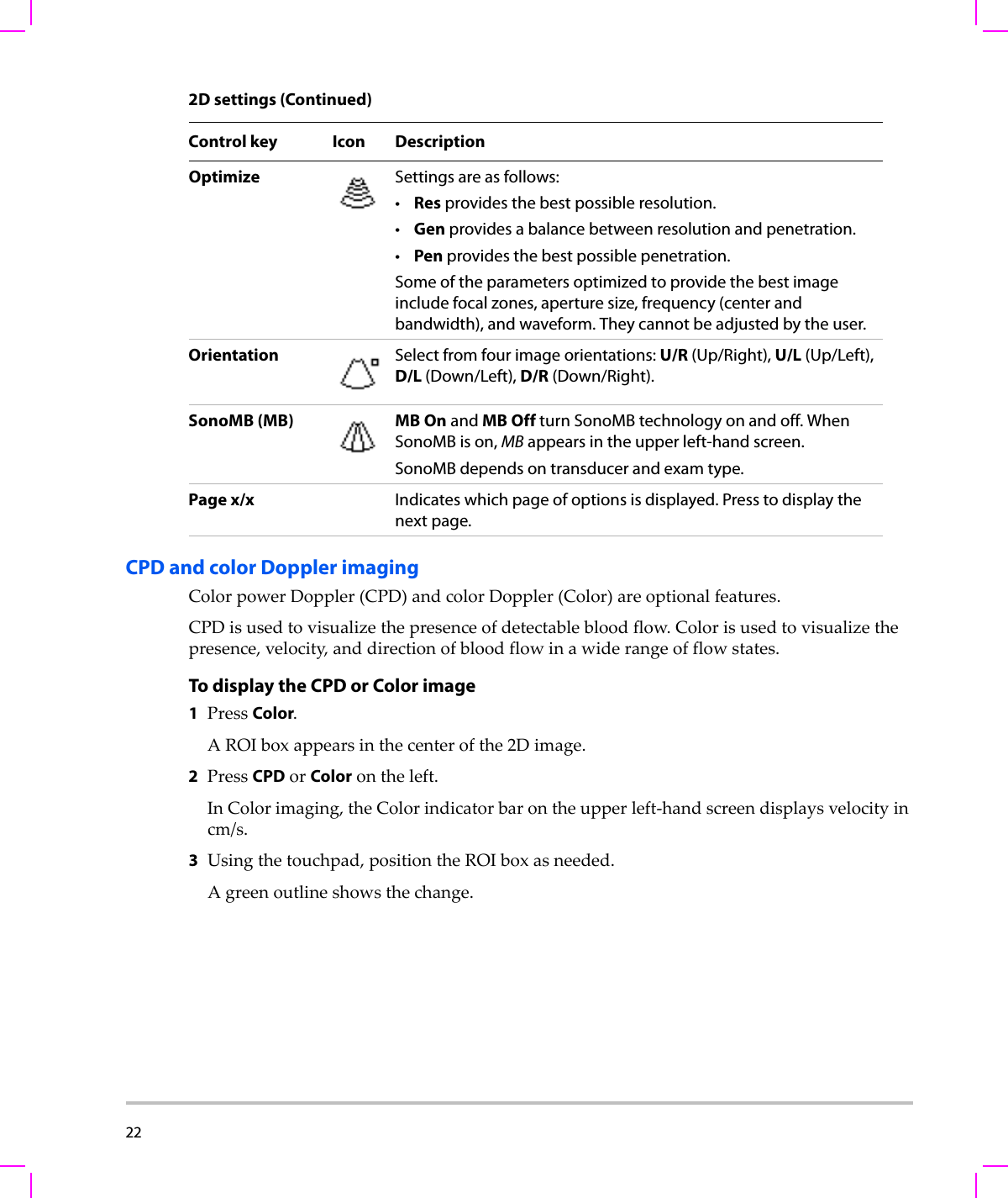
22  CPD and color Doppler imagingColorpowerDoppler(CPD)andcolorDoppler(Color)areoptionalfeatures.CPDisusedtovisualizethepresenceofdetectablebloodflow.Colorisusedtovisualizethepresence,velocity,anddirectionofbloodflowinawiderangeofflowstates.To display the CPD or Color image1PressColor.AROIboxappearsinthecenterofthe2Dimage.2PressCPDorColorontheleft.InColorimaging,theColorindicatorbarontheupperleft‐handscreendisplaysvelocityincm/s.3Usingthetouchpad,positiontheROIboxasneeded.Agreenoutlineshowsthechange.Optimize Settings are as follows:•Res provides the best possible resolution.•Gen provides a balance between resolution and penetration.•Pen provides the best possible penetration.Some of the parameters optimized to provide the best image include focal zones, aperture size, frequency (center and bandwidth), and waveform. They cannot be adjusted by the user. Orientation Select from four image orientations: U/R (Up/Right), U/L (Up/Left), D/L (Down/Left), D/R (Down/Right).SonoMB (MB) MB On and MB Off turn SonoMB technology on and off. When SonoMB is on, MB appears in the upper left-hand screen.SonoMB depends on transducer and exam type. Page x/x Indicates which page of options is displayed. Press to display the next page.2D settings (Continued)Control key Icon Description
Chapter 3:  Imaging 23ImagingAdjusting depth and gainTo adjust depthYoucanadjustthedepthinallimagingmodes.Theverticaldepthscaleismarkedin0.5 cm,1cm,and5cmincrements,dependingonthedepth.Tochangethestyleofdepthmarkers,see“Presetssetup”onpage 19.TurntheDepthknob:•Rightincreasesthedisplayeddepth.•Leftdecreasesthedisplayeddepth.To adjust gain manuallyToadjustgainautomaticallyin2D,see“2Dsettings”onpage 21.1Presstheleft‐handknobtoselectasetting:•Nearadjuststhegainappliedtothenearfieldoftheimage.•Faradjuststhegainappliedtothefarfieldoftheimage.•Gain  adjuststheoverallgainappliedtotheentireimage.InCPDorColorimaging,theOverallsettingaffectsthecolorgainappliedtotheregionofinterest(ROI)box.TheNearandFarsettingsaffectonlythe2Dimage.(Nearandfarcorrespondtothetimegaincompensation[TGC]controlsonotherultrasoundsystems.)2Turntheknob.Freezing, viewing frames, and zoomingTo freeze or unfreeze an imagePressFreeze.Onafrozenimage,thecineiconandframenumberappearinthesystemstatusarea.To move forward or backward in the cine bufferOnafrozenimage,turnthecineknob.Thetotalnumberofframesappearsnexttothecineicon.Thenumberchangestothecurrentframenumberasyoumoveforwardorbackward.
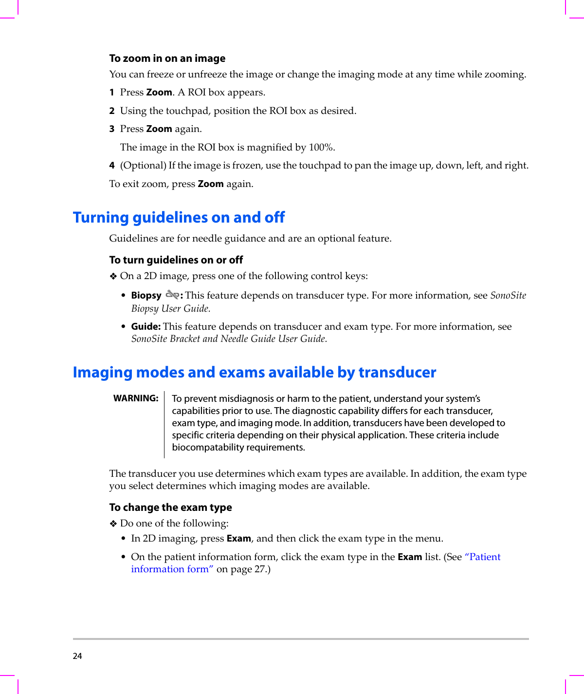
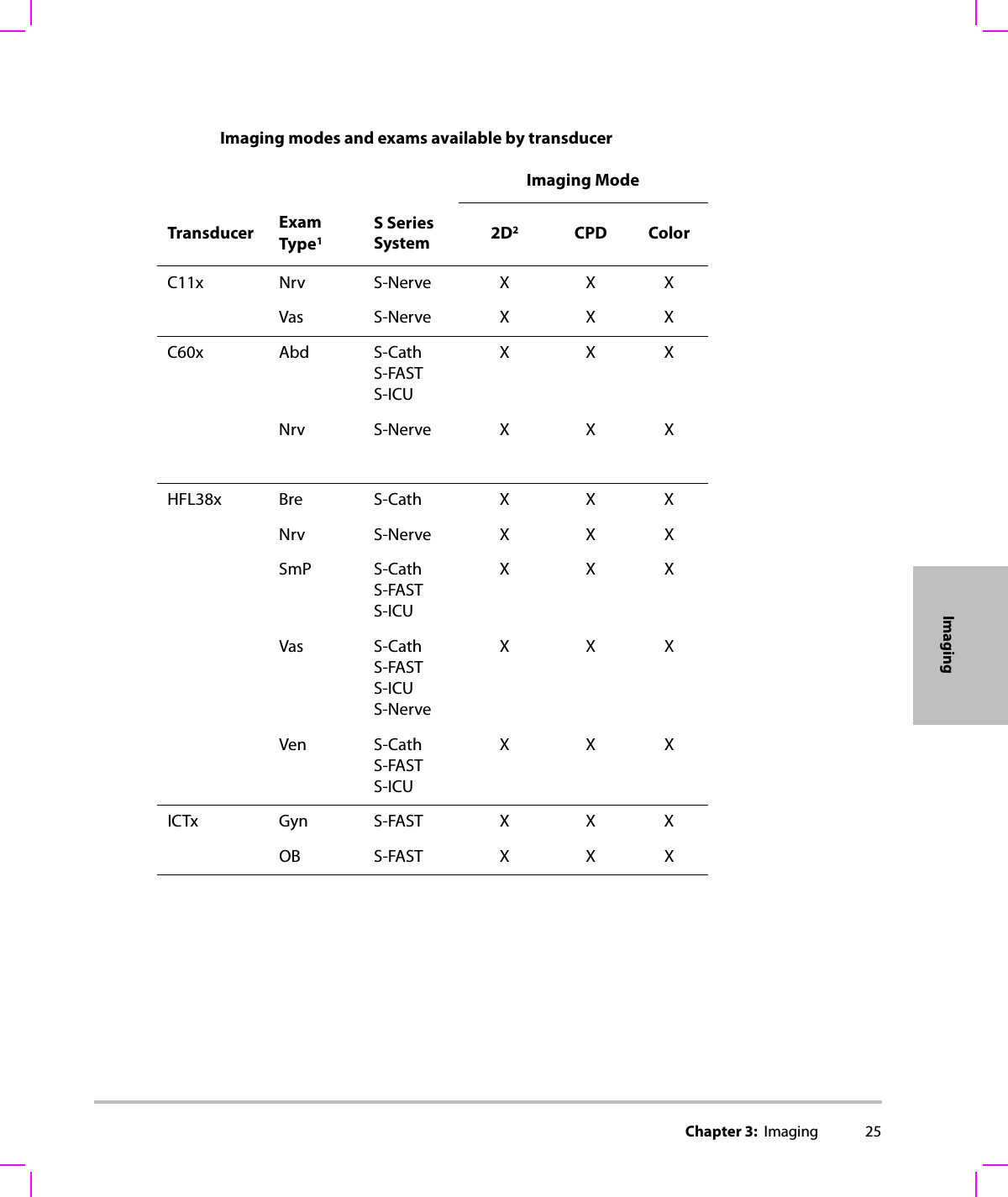
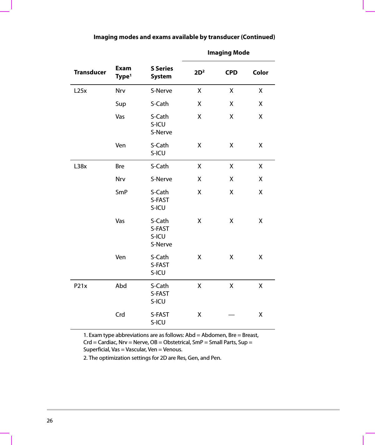
24  To zoom in on an imageYoucanfreezeorunfreezetheimageorchangetheimagingmodeatanytimewhilezooming.1PressZoom.AROIboxappears.2Usingthetouchpad,positiontheROIboxasdesired.3PressZoomagain.TheimageintheROIboxismagnifiedby100%.4(Optional)Iftheimageisfrozen,usethetouchpadtopantheimageup,down,left,andright.Toexitzoom,pressZoomagain.Turning guidelines on and offGuidelinesareforneedleguidanceandareanoptionalfeature.To turn guidelines on or offOna2Dimage,pressoneofthefollowingcontrolkeys:•Biopsy: Thisfeaturedependsontransducertype.Formoreinformation,seeSonoSiteBiopsyUserGuide.•Guide: Thisfeaturedependsontransducerandexamtype.Formoreinformation,seeSonoSiteBracketandNeedleGuideUserGuide.Imaging modes and exams available by transducerThetransduceryouusedetermineswhichexamtypesareavailable.Inaddition,theexamtypeyouselectdetermineswhichimagingmodesareavailable.To change the exam typeDooneofthefollowing:•In2Dimaging,pressExam,andthenclicktheexamtypeinthemenu.•Onthepatientinformationform,clicktheexamtypeintheExamlist.(See“Patientinformationform”onpage 27.)WARNING: To prevent misdiagnosis or harm to the patient, understand your system’s capabilities prior to use. The diagnostic capability differs for each transducer, exam type, and imaging mode. In addition, transducers have been developed to specific criteria depending on their physical application. These criteria include biocompatability requirements.
Chapter 3:  Imaging 25ImagingImaging modes and exams available by transducerImaging ModeTransducer ExamType1S SeriesSystem 2D2CPD ColorC11x Nrv S-Nerve X X XVas S-Nerve X X XC60x Abd S-CathS-FASTS-ICUXXXNrv S-Nerve X X XHFL38x Bre S-Cath X X XNrv S-Nerve X X XSmP S-CathS-FASTS-ICUXXXVas S-CathS-FASTS-ICUS-NerveXXXVen S-CathS-FASTS-ICUXXXICTx Gyn S-FAST X X XOB S-FAST X X X
26  L25x Nrv S-Nerve X X XSup S-Cath X X XVas S-CathS-ICUS-NerveXXXVen S-CathS-ICUXXXL38x Bre S-Cath X X XNrv S-Nerve X X XSmP S-CathS-FASTS-ICUXXXVas S-CathS-FASTS-ICUS-NerveXXXVen S-CathS-FASTS-ICUXXXP21x Abd S-CathS-FASTS-ICUXXXCrd S-FASTS-ICUX—X1. Exam type abbreviations are as follows: Abd = Abdomen, Bre = Breast, Crd = Cardiac, Nrv = Nerve, OB = Obstetrical, SmP = Small Parts, Sup = Superficial, Vas = Vascular, Ven = Venous.2. The optimization settings for 2D are Res, Gen, and Pen.Imaging modes and exams available by transducer (Continued)Imaging ModeTransducer ExamType1S SeriesSystem 2D2CPD Color
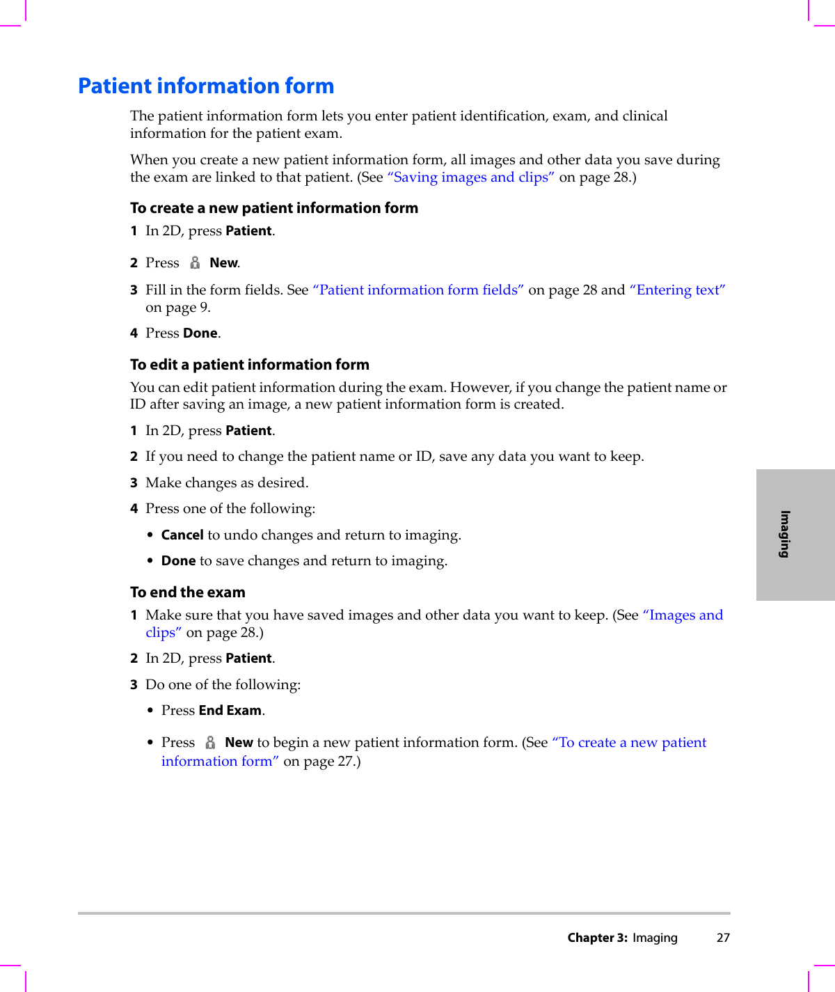
Chapter 3:  Imaging 27ImagingPatient information formThepatientinformationformletsyouenterpatientidentification,exam,andclinicalinformationforthepatientexam.Whenyoucreateanewpatientinformationform,allimagesandotherdatayousaveduringtheexamarelinkedtothatpatient.(See“Savingimagesandclips”onpage 28.)To create a new patient information form1In2D,pressPatient.2PressNew.3Fillintheformfields.See“Patientinformationformfields”onpage 28and“Enteringtext”onpage 9.4PressDone.To edit a patient information formYoucaneditpatientinformationduringtheexam.However,ifyouchangethepatientnameorIDaftersavinganimage,anewpatientinformationformiscreated.1In2D,pressPatient.2IfyouneedtochangethepatientnameorID,saveanydatayouwanttokeep.3Makechangesasdesired.4Pressoneofthefollowing:•Canceltoundochangesandreturntoimaging.•Donetosavechangesandreturntoimaging.To end the exam1Makesurethatyouhavesavedimagesandotherdatayouwanttokeep.(See“Imagesandclips”onpage 28.)2In2D,pressPatient.3Dooneofthefollowing:•PressEnd Exam.•Press Newtobeginanewpatientinformationform.(See“Tocreateanewpatientinformationform”onpage 27.)
28  Patient information form fieldsImages and clipsSaving images and clipsWhenyousaveanimageorclip,itsavestointernalstorage.ThesystembeepsafterwardifBeepAlertison,andthepercentageiconflashes.(See“A u d i o , Batterysetup”onpage 18.)Thepercentageiconshowsthepercentageofspaceusedininternalstorage.Toreceivealertswhenstorageisnearcapacity,see“Toreceivestoragealerts”onpage 18.Toaccesssavedimagesandclips,openthepatientlist.See“Reviewingimagesandclips.”To save an imagePressSave.To save a clipPressClip.Tospecifycliplength,see“Presetssetup”onpage 19.Reviewing images and clipsThepatientlistletsyouorganizesavedimagesandclipsfromacentrallocation.Field DescriptionLastFirstPatient nameID Patient identification numberExam Exam typeExam label Exam-specific label that appears in the lower-right screenUser User initials, up to 3 characters. Appears in the patient list and image header.Institution Institution name. Appears in the image header.Caution: If the internal storage icon does not appear in the system status area, internal storage may be defective. Contact SonoSite Technical Support. (See “SonoSite Technical Support” on page viii.)
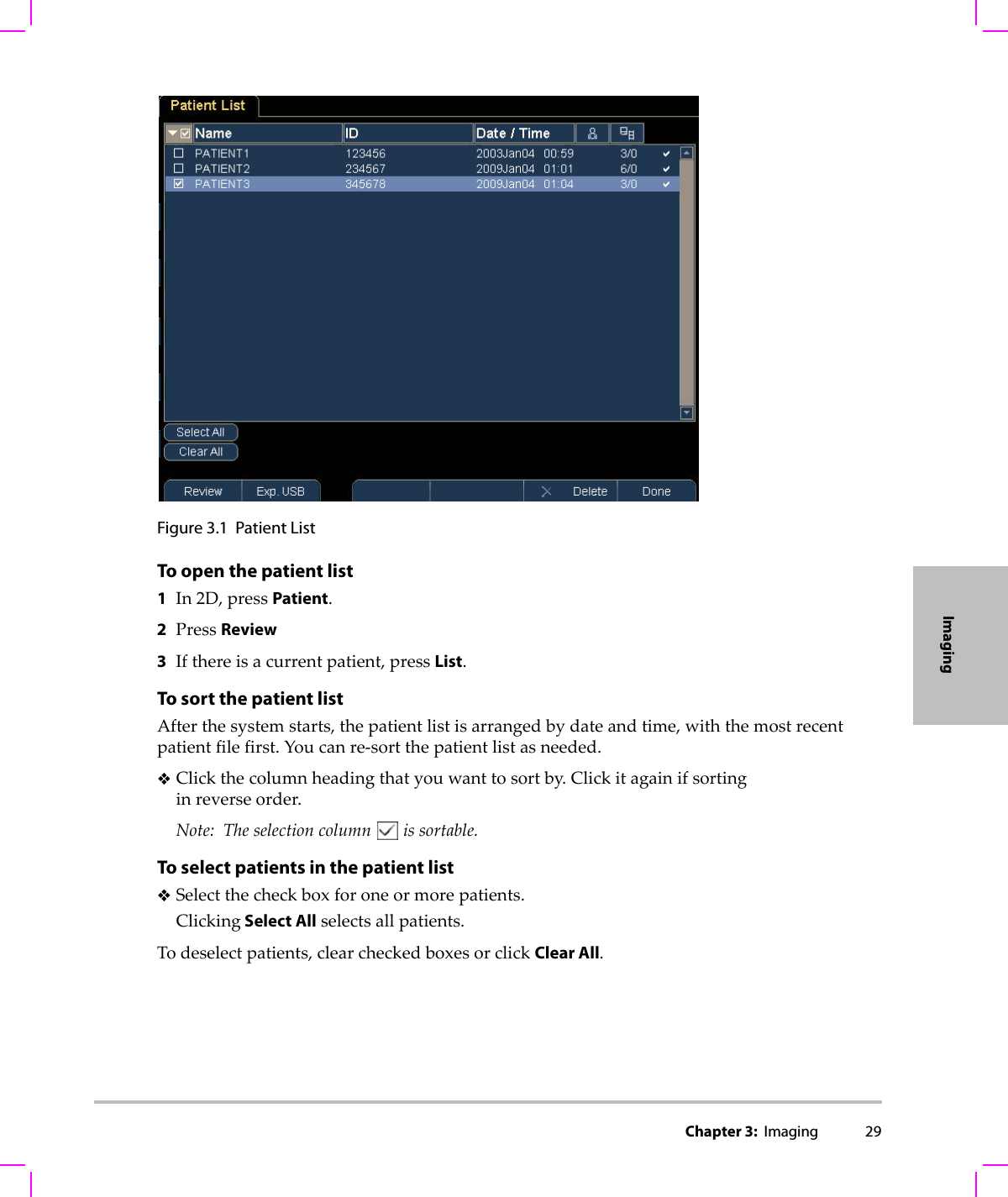
Chapter 3:  Imaging 29ImagingFigure 3.1 Patient ListTo open the patient list1In2D,pressPatient.2PressReview3Ifthereisacurrentpatient,pressList.To sort the patient listAfterthesystemstarts,thepatientlistisarrangedbydateandtime,withthemostrecentpatientfilefirst.Youcanre‐sortthepatientlistasneeded.Clickthecolumnheadingthatyouwanttosortby.Clickitagainifsortinginreverseorder.Note: Theselectioncolumnissortable.To select patients in the patient listSelectthecheckboxforoneormorepatients.Clicking Select Allselectsallpatients.Todeselectpatients,clearcheckedboxesorclickClear All.
30  To review images and clipsYoucanreviewonlyonepatient’simagesandclipsatatime.1Inthepatientlist,clickthepatientwhoseimagesandclipsyouwanttoreview.Thepatientrowishighlighted.2PresstheReviewknob.Theiconontheknobchangestotwonumbers:thefiledisplayedandthetotalfilessaved.3Turntheknobtocycletotheimageorclipyouwanttoreview4(ClipOnly)PressthePlaykey.Theclipplaysautomaticallyafterloading.Theloadtimedependsoncliplength.YoucanpressthePausekeytofreezetheclipandcanturntheright‐handknob foraplaybackspeed.5Turntheleft‐handknobx/xtocycletothenextimageorclipyouwanttoview.Toreturntothepatientlist,pressList.Toreturntoimaging,pressDone.Printing, exporting, and deleting images and clipsTo print an image1Verifythataprinterisselected.See“Toconfigurethesystemforaprinter”onpage 18.2Dooneofthefollowing:•Inthepatientlist,reviewthepatient’simages.PressPrintwhentheimageappears.• Freezetheimage,andpressPrint.To print multiple images1Verifythataprinterisselected.See“Toconfigurethesystemforaprinter”onpage 18.2Dooneofthefollowing:•Printallimagesformultiplepatients:Selectoneormorepatientsinthepatientlist.Thenpress Print.•Printallimagesforonepatient:Highlightthepatientinthepatientlist,andpressPrint.Eachimageappearsbrieflyon‐screenwhileprinting.WARNING: To avoid damaging the USB storage device and losing patient data from it, observe the following:• Do not remove the USB storage device or turn off the ultrasound system while the system is exporting.• Do not bump or otherwise apply pressure to the USB storage device while it is in a USB port on the ultrasound system. The connector could break.
Chapter 3:  Imaging 31ImagingTo export images and clips to a USB storage deviceAUSBstoragedeviceisfortemporarystorageofimagesandclips.Patientexamsshouldbearchivedregularly.Tospecifyfileformat,see“USBDevicessetup”onpage 20.Apatientexammustbeendedbeforeyoucanexportitsimagesandclips.See“Toendtheexam.”1InserttheUSBstoragedevice.(See“InsertingandremovingUSBstoragedevices”onpage 6.)2Inthepatientlist,selectthepatientswhoseimagesandclipsyouwanttoexport.3SelectExp. USB on‐screen.AlistofUSBdevicesappears.4SelecttheUSBstoragedevice,andselectExport.OnlyavailableUSBdevices(forexample,notpassword‐protected)areselectable.ThefilesarefinishedexportingapproximatelyfivesecondsaftertheUSBanimationstops.RemovingtheUSBstoragedeviceorturningoffthesystemwhileexportingmaycauseexportedfilestobecorruptedorincomplete.Tostopin‐progressexporting,selectCancel Export.To delete images and clips1Selectoneormorepatientsinthepatientlist.2SelectDeletetodeletetheselectedpatients.Aconfirmationscreenappears.
32
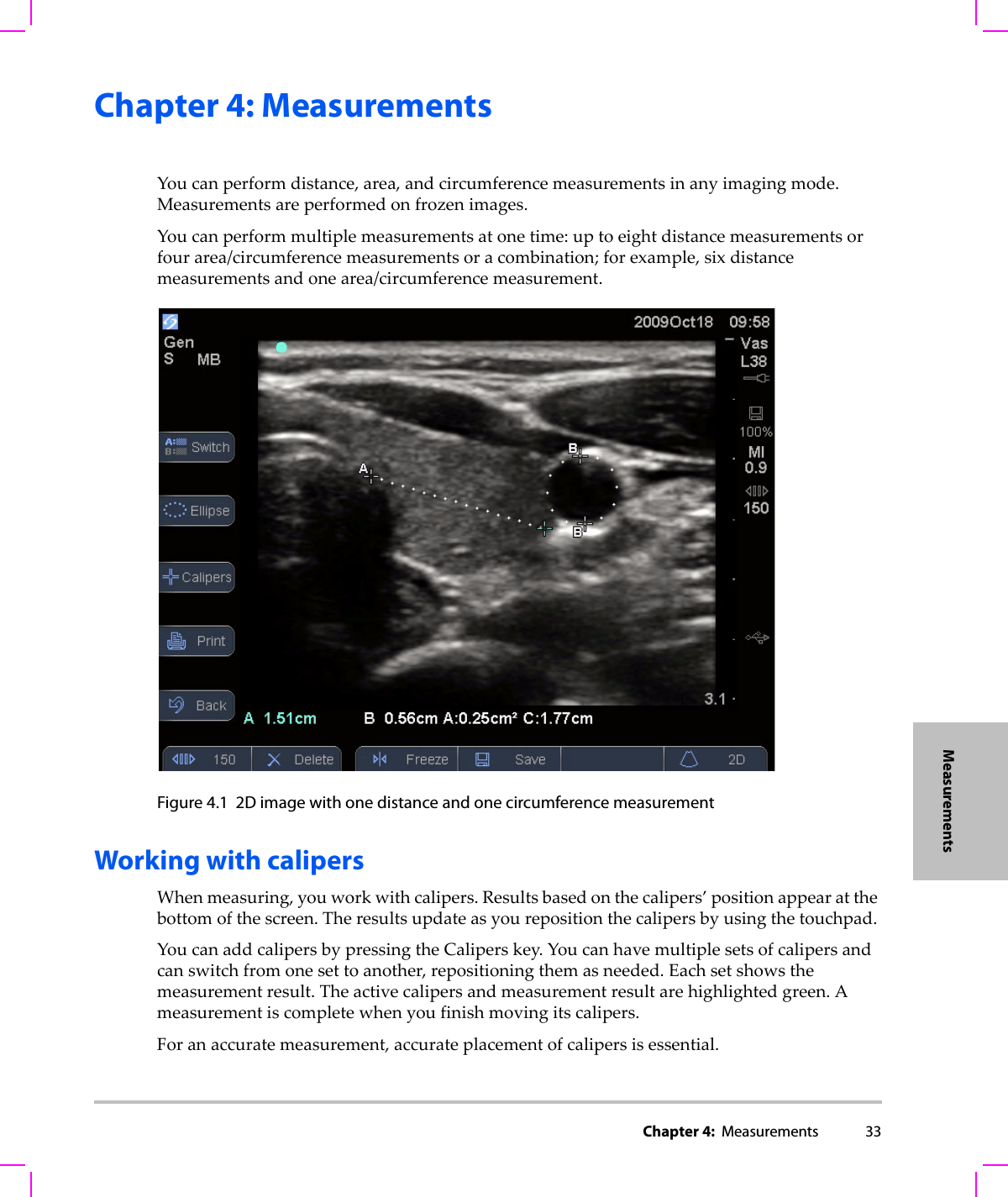
Chapter 4:  Measurements 33MeasurementsChapter 4: Measurements Youcanperformdistance,area,andcircumferencemeasurementsinanyimagingmode.Measurementsareperformedonfrozenimages.Youcanperformmultiplemeasurementsatonetime:uptoeightdistancemeasurementsorfourarea/circumferencemeasurementsoracombination;forexample,sixdistancemeasurementsandonearea/circumferencemeasurement.Figure 4.1 2D image with one distance and one circumference measurement Working with calipersWhenmeasuring,youworkwithcalipers.Resultsbasedonthecalipers’positionappearatthebottomofthescreen.Theresultsupdateasyourepositionthecalipersbyusingthetouchpad.YoucanaddcalipersbypressingtheCaliperskey.Youcanhavemultiplesetsofcalipersandcanswitchfromonesettoanother,repositioningthemasneeded.Eachsetshowsthemeasurementresult.Theactivecalipersandmeasurementresultarehighlightedgreen.Ameasurementiscompletewhenyoufinishmovingitscalipers.Foranaccuratemeasurement,accurateplacementofcalipersisessential.
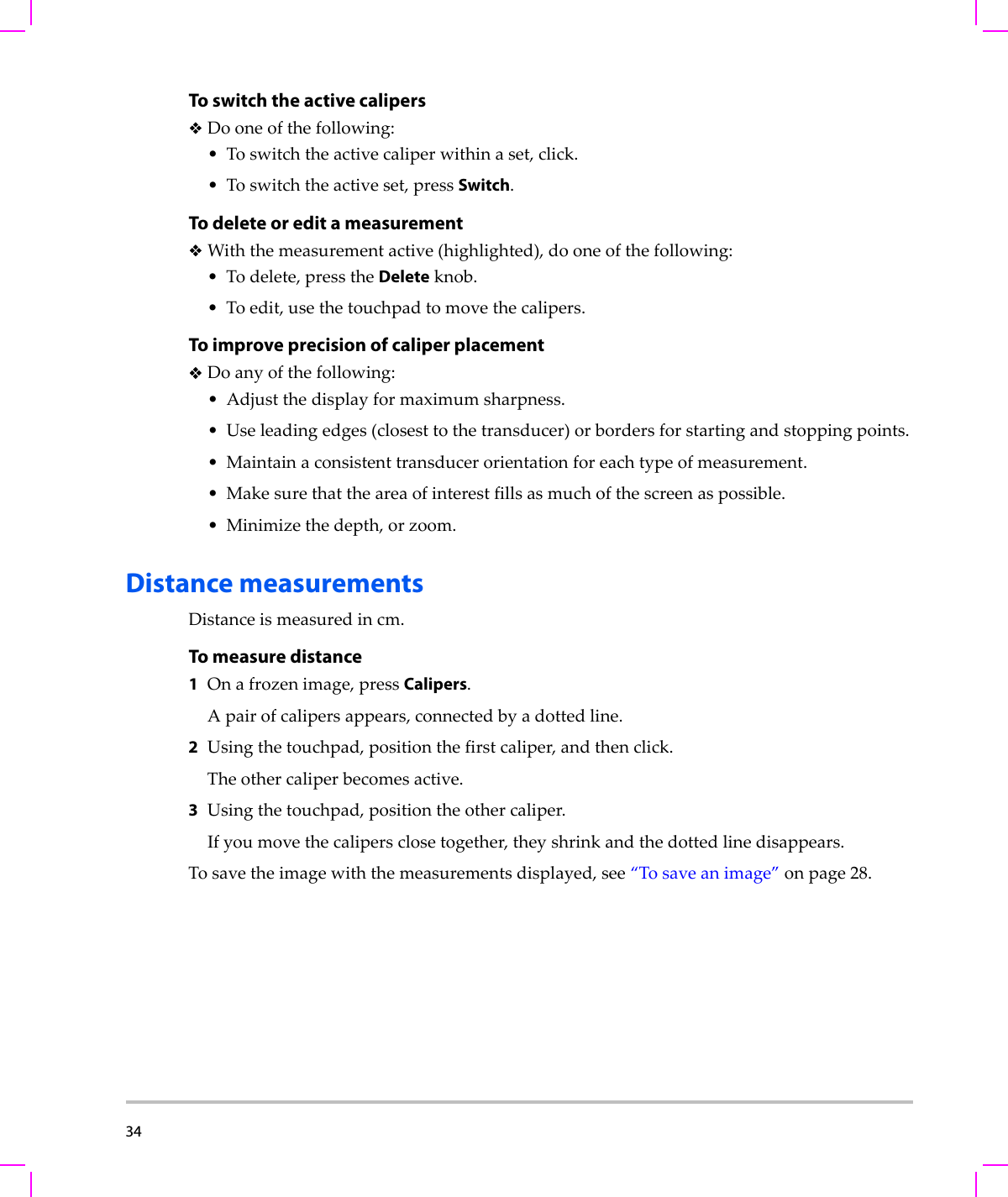
34  To switch the active calipersDooneofthefollowing:•Toswitchtheactivecaliperwithinaset,click.•Toswitchtheactiveset,pressSwitch.To delete or edit a measurementWiththemeasurementactive(highlighted),dooneofthefollowing:•Todelete,presstheDeleteknob.•Toedit,usethetouchpadtomovethecalipers.To improve precision of caliper placement Doanyofthefollowing:•Adjustthedisplayformaximumsharpness.•Useleadingedges(closesttothetransducer)orbordersforstartingandstoppingpoints.• Maintainaconsistenttransducerorientationforeachtypeofmeasurement.•Makesurethattheareaofinterestfillsasmuchofthescreenaspossible.• Minimizethedepth,orzoom.Distance measurementsDistanceismeasuredincm.To measure distance1Onafrozenimage,pressCalipers.Apairofcalipersappears,connectedbyadottedline.2Usingthetouchpad,positionthefirstcaliper,andthenclick.Theothercaliperbecomesactive.3Usingthetouchpad,positiontheothercaliper.Ifyoumovethecalipersclosetogether,theyshrinkandthedottedlinedisappears.Tosavetheimagewiththemeasurementsdisplayed,see“Tosaveanimage”onpage 28.
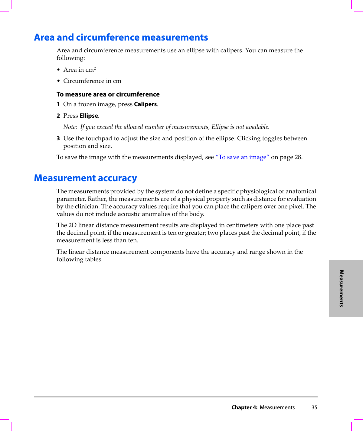
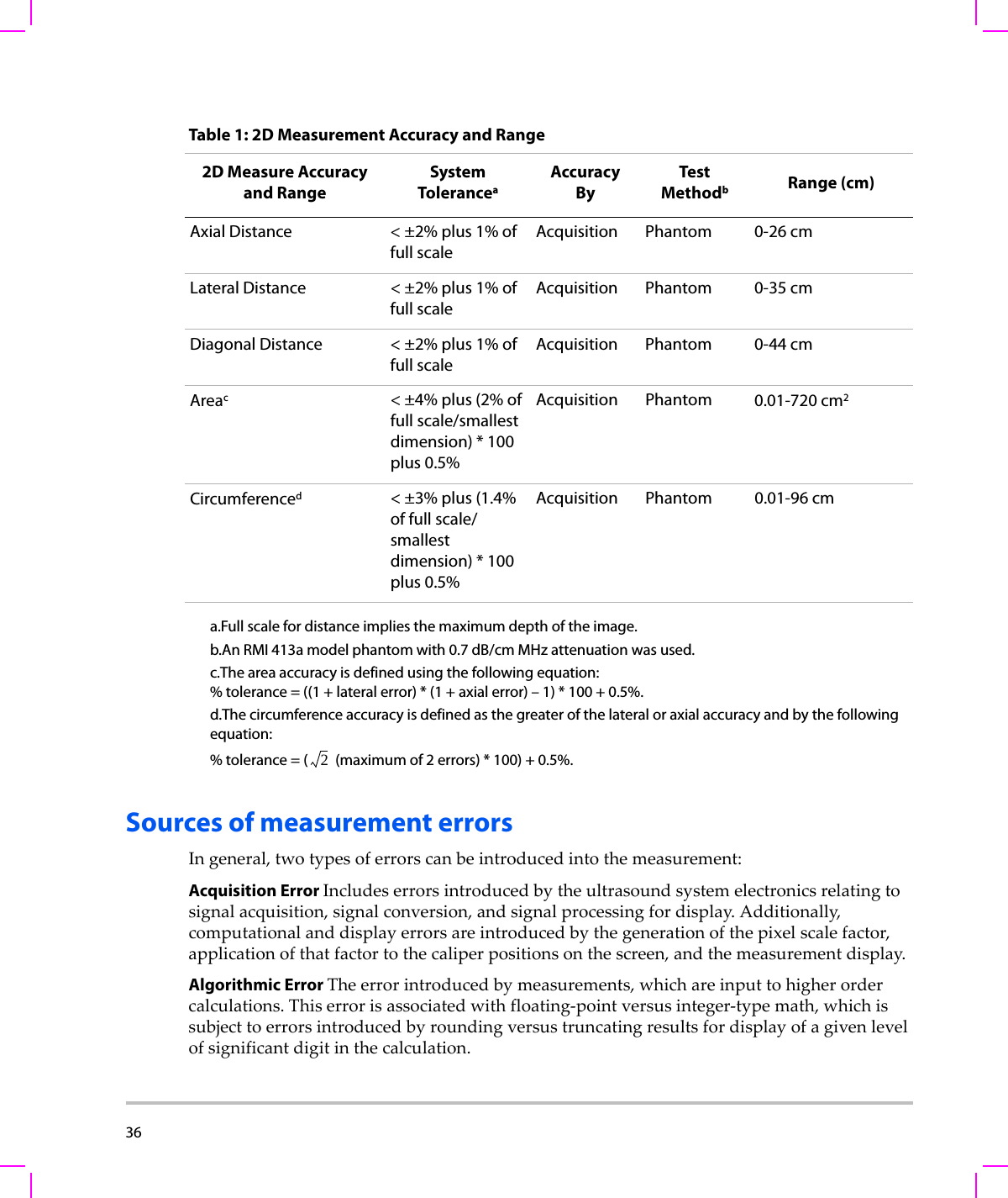
Chapter 4:  Measurements 35MeasurementsArea and circumference measurementsAreaandcircumferencemeasurementsuseanellipsewithcalipers.Youcanmeasurethefollowing:•Areaincm2• CircumferenceincmTo measure area or circumference1Onafrozenimage,pressCalipers.2PressEllipse.Note: Ifyouexceedtheallowednumberofmeasurements,Ellipseisnotavailable.3Usethetouchpadtoadjustthesizeandpositionoftheellipse.Clickingtogglesbetweenpositionandsize.Tosavetheimagewiththemeasurementsdisplayed,see“Tosaveanimage”onpage 28.Measurement accuracyThemeasurementsprovidedbythesystemdonotdefineaspecificphysiologicaloranatomicalparameter.Rather,themeasurementsareofaphysicalpropertysuchasdistanceforevaluationbytheclinician.Theaccuracyvaluesrequirethatyoucanplacethecalipersoveronepixel.Thevaluesdonotincludeacousticanomaliesofthebody.The2Dlineardistancemeasurementresultsaredisplayedincentimeterswithoneplacepastthedecimalpoint,ifthemeasurementistenorgreater;twoplacespastthedecimalpoint,ifthemeasurementislessthanten.Thelineardistancemeasurementcomponentshavetheaccuracyandrangeshowninthefollowingtables.
36  Sources of measurement errorsIngeneral,twotypesoferrorscanbeintroducedintothemeasurement:Acquisition Error Includeserrorsintroducedbytheultrasoundsystemelectronicsrelatingtosignalacquisition,signalconversion,andsignalprocessingfordisplay.Additionally,computationalanddisplayerrorsareintroducedbythegenerationofthepixelscalefactor,applicationofthatfactortothecaliperpositionsonthescreen,andthemeasurementdisplay.Algorithmic Error Theerrorintroducedbymeasurements,whichareinputtohigherordercalculations.Thiserrorisassociatedwithfloating‐pointversusinteger‐typemath,whichissubjecttoerrorsintroducedbyroundingversustruncatingresultsfordisplayofagivenlevelofsignificantdigitinthecalculation.Table 1: 2D Measurement Accuracy and Range2D Measure Accuracy and RangeSystem ToleranceaAccuracy ByTes t MethodbRange (cm)Axial Distance < ±2% plus 1% of full scaleAcquisition Phantom 0-26 cmLateral Distance < ±2% plus 1% of full scaleAcquisition Phantom 0-35 cmDiagonal Distance < ±2% plus 1% of full scaleAcquisition Phantom 0-44 cmAreac< ±4% plus (2% of full scale/smallest dimension) * 100 plus 0.5%Acquisition Phantom 0.01-720 cm2Circumferenced< ±3% plus (1.4% of full scale/ smallest dimension) * 100 plus 0.5%Acquisition Phantom 0.01-96 cma.Full scale for distance implies the maximum depth of the image.b.An RMI 413a model phantom with 0.7 dB/cm MHz attenuation was used.c.The area accuracy is defined using the following equation:% tolerance = ((1 + lateral error) * (1 + axial error) – 1) * 100 + 0.5%.d.The circumference accuracy is defined as the greater of the lateral or axial accuracy and by the following equation: % tolerance = (  (maximum of 2 errors) * 100) + 0.5%.2
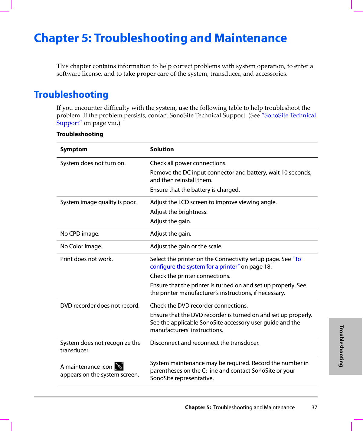
Chapter 5:  Troubleshooting and Maintenance 37TroubleshootingChapter 5: Troubleshooting and MaintenanceThischaptercontainsinformationtohelpcorrectproblemswithsystemoperation,toenterasoftwarelicense,andtotakepropercareofthesystem,transducer,andaccessories.TroubleshootingIfyouencounterdifficultywiththesystem,usethefollowingtabletohelptroubleshoottheproblem.Iftheproblempersists,contactSonoSiteTechnicalSupport.(See“SonoSiteTechnicalSupport”onpage viii.)TroubleshootingSymptom SolutionSystem does not turn on. Check all power connections.Remove the DC input connector and battery, wait 10 seconds, and then reinstall them.Ensure that the battery is charged.System image quality is poor. Adjust the LCD screen to improve viewing angle.Adjust the brightness.Adjust the gain.No CPD image. Adjust the gain.No Color image. Adjust the gain or the scale.Print does not work. Select the printer on the Connectivity setup page. See “To configure the system for a printer” on page 18.Check the printer connections.Ensure that the printer is turned on and set up properly. See the printer manufacturer’s instructions, if necessary.DVD recorder does not record. Check the DVD recorder connections.Ensure that the DVD recorder is turned on and set up properly. See the applicable SonoSite accessory user guide and the manufacturers’ instructions.System does not recognize the transducer.Disconnect and reconnect the transducer.A maintenance icon   appears on the system screen.System maintenance may be required. Record the number in parentheses on the C: line and contact SonoSite or your SonoSite representative.
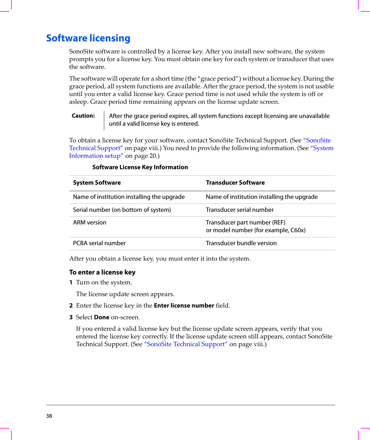
38  Software licensingSonoSitesoftwareiscontrolledbyalicensekey.Afteryouinstallnewsoftware,thesystempromptsyouforalicensekey.Youmustobtainonekeyforeachsystemortransducerthatusesthesoftware.Thesoftwarewilloperateforashorttime(the“graceperiod”)withoutalicensekey.Duringthegraceperiod,allsystemfunctionsareavailable.Afterthegraceperiod,thesystemisnotusableuntilyouenteravalidlicensekey.Graceperiodtimeisnotusedwhilethesystemisofforasleep.Graceperiodtimeremainingappearsonthelicenseupdatescreen.Toobtainalicensekeyforyoursoftware,contactSonoSiteTechnicalSupport.(See“SonoSiteTechnicalSupport”onpage viii.)Youneedtoprovidethefollowinginformation.(See“SystemInformationsetup”onpage 20.)Afteryouobtainalicensekey,youmustenteritintothesystem.To enter a license key1Turnonthesystem.Thelicenseupdatescreenappears.2EnterthelicensekeyintheEnter license numberfield.3SelectDoneon‐screen.Ifyouenteredavalidlicensekeybutthelicenseupdatescreenappears,verifythatyouenteredthelicensekeycorrectly.Ifthelicenseupdatescreenstillappears,contactSonoSiteTechnicalSupport.(See“SonoSiteTechnicalSupport”onpage viii.)Caution: After the grace period expires, all system functions except licensing are unavailable until a valid license key is entered.Software License Key InformationSystem Software Transducer Software Name of institution installing the upgrade Name of institution installing the upgradeSerial number (on bottom of system) Transducer serial numberARM version Transducer part number (REF)or model number (for example, C60x)PCBA serial number Transducer bundle version
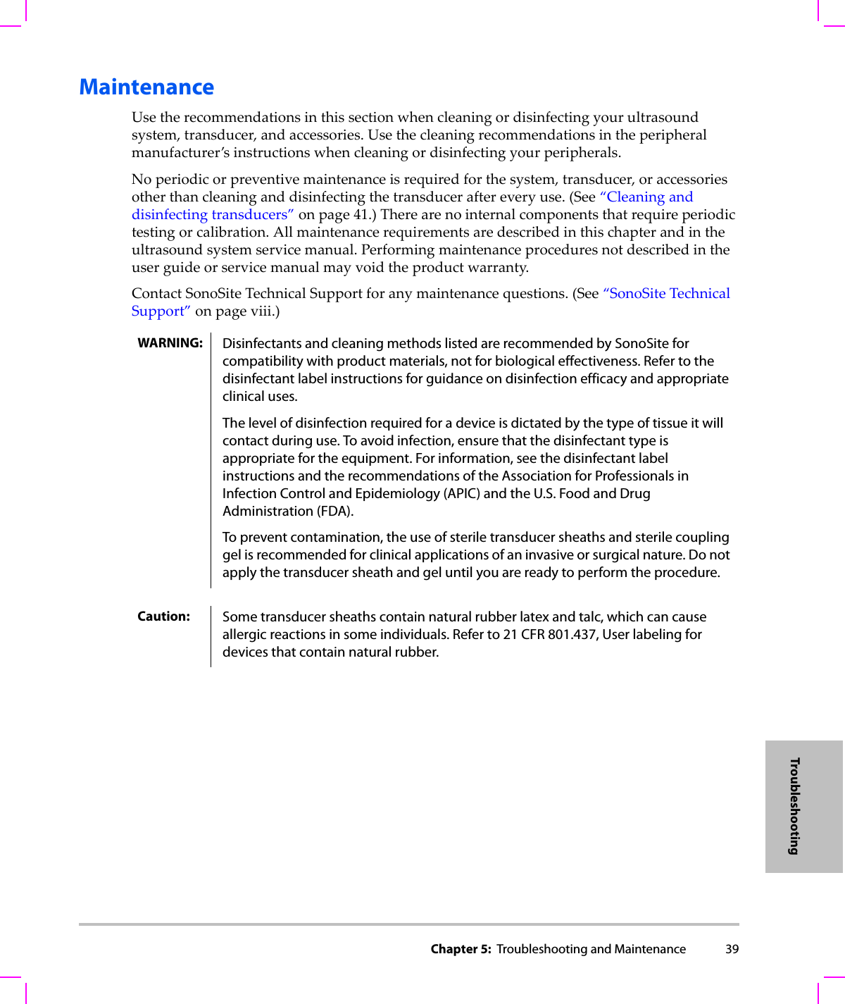
Chapter 5:  Troubleshooting and Maintenance 39TroubleshootingMaintenanceUsetherecommendationsinthissectionwhencleaningordisinfectingyourultrasoundsystem,transducer,andaccessories.Usethecleaningrecommendationsintheperipheralmanufacturer’sinstructionswhencleaningordisinfectingyourperipherals.Noperiodicorpreventivemaintenanceisrequiredforthesystem,transducer,oraccessoriesotherthancleaninganddisinfectingthetransduceraftereveryuse.(See“Cleaninganddisinfectingtransducers”onpage 41.)Therearenointernalcomponentsthatrequireperiodictestingorcalibration.Allmaintenancerequirementsaredescribedinthischapterandintheultrasoundsystemservicemanual.Performingmaintenanceproceduresnotdescribedintheuserguideorservicemanualmayvoidtheproductwarranty.ContactSonoSiteTechnicalSupportforanymaintenancequestions.(See“SonoSiteTechnicalSupport”onpage viii.)WARNING: Disinfectants and cleaning methods listed are recommended by SonoSite for compatibility with product materials, not for biological effectiveness. Refer to the disinfectant label instructions for guidance on disinfection efficacy and appropriate clinical uses. The level of disinfection required for a device is dictated by the type of tissue it will contact during use. To avoid infection, ensure that the disinfectant type is appropriate for the equipment. For information, see the disinfectant label instructions and the recommendations of the Association for Professionals in Infection Control and Epidemiology (APIC) and the U.S. Food and Drug Administration (FDA).To prevent contamination, the use of sterile transducer sheaths and sterile coupling gel is recommended for clinical applications of an invasive or surgical nature. Do not apply the transducer sheath and gel until you are ready to perform the procedure.Caution: Some transducer sheaths contain natural rubber latex and talc, which can cause allergic reactions in some individuals. Refer to 21 CFR 801.437, User labeling for devices that contain natural rubber.
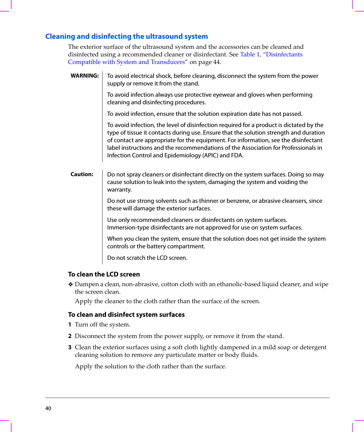
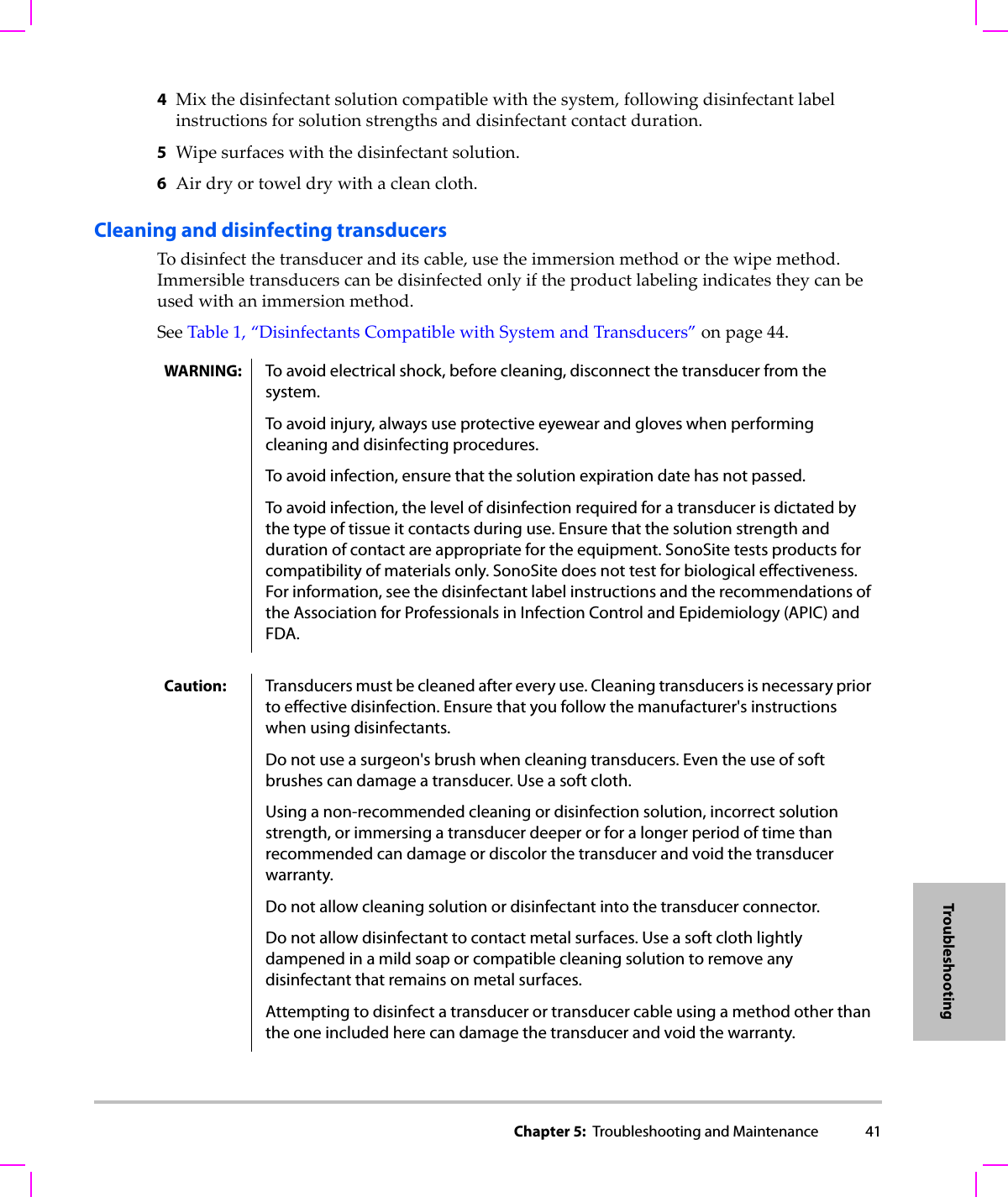
40  Cleaning and disinfecting the ultrasound systemTheexteriorsurfaceoftheultrasoundsystemandtheaccessoriescanbecleanedanddisinfectedusingarecommendedcleanerordisinfectant.SeeTable 1,“DisinfectantsCompatiblewithSystemandTransducers”onpage 44.To clean the LCD screenDampenaclean,non‐abrasive,cottonclothwithanethanolic‐basedliquidcleaner,andwipethescreenclean.Applythecleanertotheclothratherthanthesurfaceofthescreen.To clean and disinfect system surfaces1Turnoffthesystem.2Disconnectthesystemfromthepowersupply,orremoveitfromthestand.3Cleantheexteriorsurfacesusingasoftclothlightlydampenedinamildsoapordetergentcleaningsolutiontoremoveanyparticulatematterorbodyfluids.Applythesolutiontotheclothratherthanthesurface.WARNING: To avoid electrical shock, before cleaning, disconnect the system from the power supply or remove it from the stand.To avoid infection always use protective eyewear and gloves when performing cleaning and disinfecting procedures.To avoid infection, ensure that the solution expiration date has not passed.To avoid infection, the level of disinfection required for a product is dictated by the type of tissue it contacts during use. Ensure that the solution strength and duration of contact are appropriate for the equipment. For information, see the disinfectant label instructions and the recommendations of the Association for Professionals in Infection Control and Epidemiology (APIC) and FDA.Caution: Do not spray cleaners or disinfectant directly on the system surfaces. Doing so may cause solution to leak into the system, damaging the system and voiding the warranty.Do not use strong solvents such as thinner or benzene, or abrasive cleansers, since these will damage the exterior surfaces.Use only recommended cleaners or disinfectants on system surfaces. Immersion-type disinfectants are not approved for use on system surfaces.When you clean the system, ensure that the solution does not get inside the system controls or the battery compartment. Do not scratch the LCD screen.
Chapter 5:  Troubleshooting and Maintenance 41Troubleshooting4Mixthedisinfectantsolutioncompatiblewiththesystem,followingdisinfectantlabelinstructionsforsolutionstrengthsanddisinfectantcontactduration.5Wipesurfaceswiththedisinfectantsolution.6Airdryortoweldrywithacleancloth.Cleaning and disinfecting transducersTodisinfectthetransduceranditscable,usetheimmersionmethodorthewipemethod.Immersibletransducerscanbedisinfectedonlyiftheproductlabelingindicatestheycanbeusedwithanimmersionmethod.SeeTable 1,“DisinfectantsCompatiblewithSystemandTransducers”onpage 44.WARNING: To avoid electrical shock, before cleaning, disconnect the transducer from the system.To avoid injury, always use protective eyewear and gloves when performing cleaning and disinfecting procedures.To avoid infection, ensure that the solution expiration date has not passed.To avoid infection, the level of disinfection required for a transducer is dictated by the type of tissue it contacts during use. Ensure that the solution strength and duration of contact are appropriate for the equipment. SonoSite tests products for compatibility of materials only. SonoSite does not test for biological effectiveness. For information, see the disinfectant label instructions and the recommendations of the Association for Professionals in Infection Control and Epidemiology (APIC) and FDA.Caution: Transducers must be cleaned after every use. Cleaning transducers is necessary prior to effective disinfection. Ensure that you follow the manufacturer's instructions when using disinfectants.Do not use a surgeon's brush when cleaning transducers. Even the use of soft brushes can damage a transducer. Use a soft cloth.Using a non-recommended cleaning or disinfection solution, incorrect solution strength, or immersing a transducer deeper or for a longer period of time than recommended can damage or discolor the transducer and void the transducer warranty.Do not allow cleaning solution or disinfectant into the transducer connector.Do not allow disinfectant to contact metal surfaces. Use a soft cloth lightly dampened in a mild soap or compatible cleaning solution to remove any disinfectant that remains on metal surfaces.Attempting to disinfect a transducer or transducer cable using a method other than the one included here can damage the transducer and void the warranty.
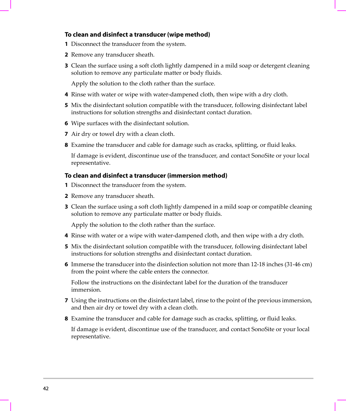
42  To clean and disinfect a transducer (wipe method)1Disconnectthetransducerfromthesystem.2Removeanytransducersheath.3Cleanthesurfaceusingasoftclothlightlydampenedinamildsoapordetergentcleaningsolutiontoremoveanyparticulatematterorbodyfluids.Applythesolutiontotheclothratherthanthesurface.4Rinsewithwaterorwipewithwater‐dampenedcloth,thenwipewithadrycloth.5Mixthedisinfectantsolutioncompatiblewiththetransducer,followingdisinfectantlabelinstructionsforsolutionstrengthsanddisinfectantcontactduration.6Wipesurfaceswiththedisinfectantsolution.7Airdryortoweldrywithacleancloth.8Examinethetransducerandcablefordamagesuchascracks,splitting,orfluidleaks.Ifdamageisevident,discontinueuseofthetransducer,andcontactSonoSiteoryourlocalrepresentative.To clean and disinfect a transducer (immersion method)1Disconnectthetransducerfromthesystem.2Removeanytransducersheath.3Cleanthesurfaceusingasoftclothlightlydampenedinamildsoaporcompatiblecleaningsolutiontoremoveanyparticulatematterorbodyfluids.Applythesolutiontotheclothratherthanthesurface.4Rinsewithwaterorawipewithwater‐dampenedcloth,andthenwipewithadrycloth.5Mixthedisinfectantsolutioncompatiblewiththetransducer,followingdisinfectantlabelinstructionsforsolutionstrengthsanddisinfectantcontactduration.6Immersethetransducerintothedisinfectionsolutionnotmorethan12‐18 inches(31‐46 cm)fromthepointwherethecableenterstheconnector.Followtheinstructionsonthedisinfectantlabelforthedurationofthetransducerimmersion.7Usingtheinstructionsonthedisinfectantlabel,rinsetothepointofthepreviousimmersion,andthenairdryortoweldrywithacleancloth.8Examinethetransducerandcablefordamagesuchascracks,splitting,orfluidleaks.Ifdamageisevident,discontinueuseofthetransducer,andcontactSonoSiteoryourlocalrepresentative.
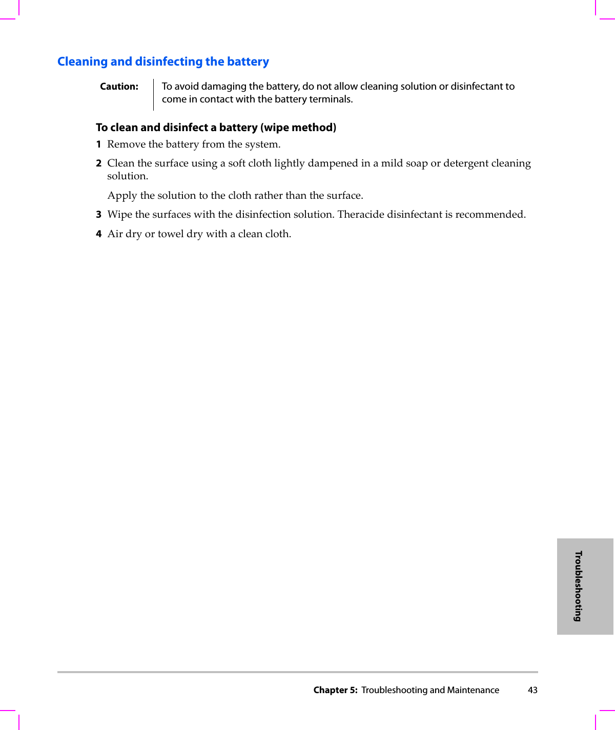
Chapter 5:  Troubleshooting and Maintenance 43TroubleshootingCleaning and disinfecting the battery To clean and disinfect a battery (wipe method)1Removethebatteryfromthesystem.2Cleanthesurfaceusingasoftclothlightlydampenedinamildsoapordetergentcleaningsolution.Applythesolutiontotheclothratherthanthesurface.3Wipethesurfaceswiththedisinfectionsolution.Theracidedisinfectantisrecommended.4Airdryortoweldrywithacleancloth.Caution: To avoid damaging the battery, do not allow cleaning solution or disinfectant to come in contact with the battery terminals.
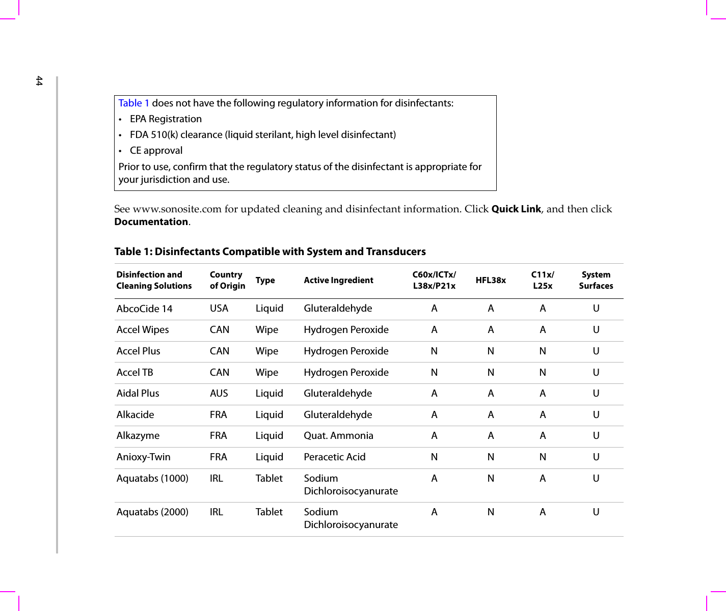
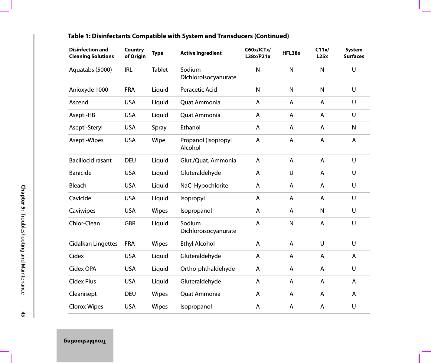
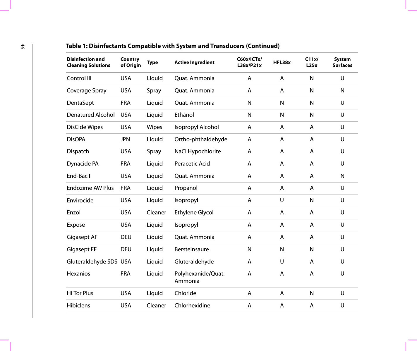
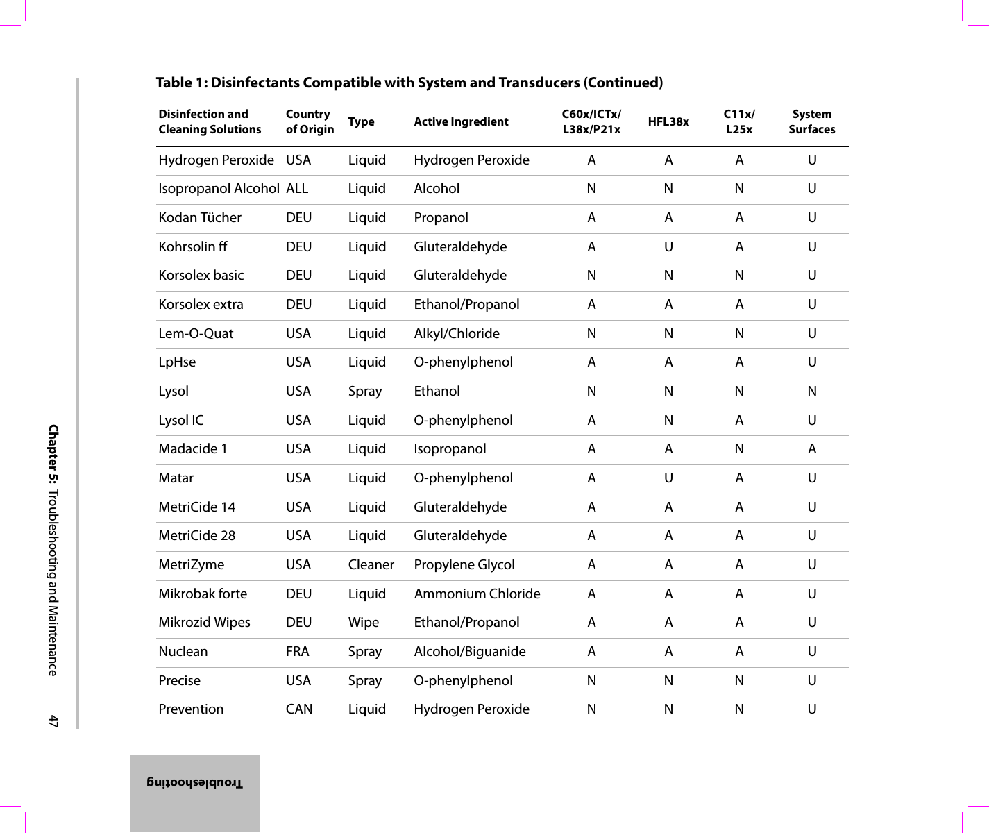
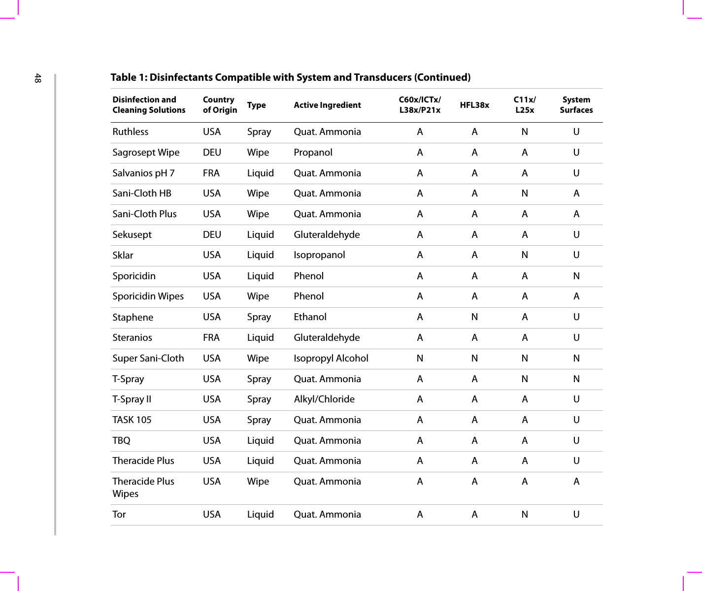
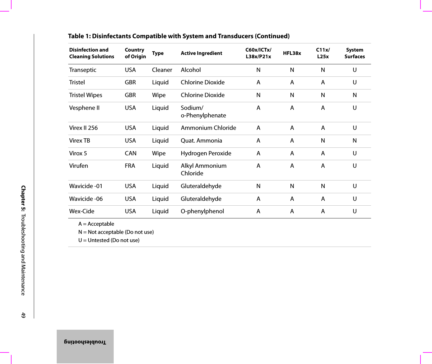
44Seewww.sonosite.comforupdatedcleaninganddisinfectantinformation.ClickQuick Link,andthenclickDocumentation.Table 1 does not have the following regulatory information for disinfectants:•EPA Registration• FDA 510(k) clearance (liquid sterilant, high level disinfectant)• CE approvalPrior to use, confirm that the regulatory status of the disinfectant is appropriate for your jurisdiction and use.Table 1: Disinfectants Compatible with System and TransducersDisinfection and Cleaning SolutionsCountry of Origin Type Active Ingredient C60x/ICTx/L38x/P21x HFL38x C11x/L25xSystem SurfacesAbcoCide 14 USA Liquid Gluteraldehyde A A A UAccel Wipes CAN Wipe Hydrogen Peroxide A A A UAccel Plus CAN Wipe Hydrogen Peroxide N N N UAccel TB CAN Wipe Hydrogen Peroxide N N N UAidal Plus AUS Liquid Gluteraldehyde A A A UAlkacide FRA Liquid Gluteraldehyde A A A UAlkazyme FRA Liquid Quat. Ammonia A A A UAnioxy-Twin FRA Liquid Peracetic Acid N N N UAquatabs (1000) IRL Tablet Sodium DichloroisocyanurateANAUAquatabs (2000) IRL Tablet Sodium DichloroisocyanurateANAU
Chapter 5:  Troubleshooting and Maintenance 45TroubleshootingAquatabs (5000) IRL Tablet Sodium DichloroisocyanurateNNNUAnioxyde 1000 FRA Liquid Peracetic Acid N N N UAscend USA Liquid Quat Ammonia A A A UAsepti-HB USA Liquid Quat Ammonia A A A UAsepti-Steryl USA Spray Ethanol A A A NAsepti-Wipes USA Wipe Propanol (Isopropyl AlcoholAAAABacillocid rasant DEU Liquid Glut./Quat. Ammonia A A A UBanicide USA Liquid Gluteraldehyde A U A UBleach USA Liquid NaCl Hypochlorite A A A UCavicide USA Liquid Isopropyl A A A UCaviwipes USA Wipes Isopropanol A A N UChlor-Clean GBR Liquid Sodium DichloroisocyanurateANAUCidalkan Lingettes FRA Wipes Ethyl Alcohol A A U UCidex USA Liquid Gluteraldehyde A A A ACidex OPA USA Liquid Ortho-phthaldehyde A A A UCidex Plus USA Liquid Gluteraldehyde A A A ACleanisept DEU Wipes Quat Ammonia A A A AClorox Wipes USA Wipes Isopropanol A A A UTable 1: Disinfectants Compatible with System and Transducers (Continued)Disinfection and Cleaning SolutionsCountry of Origin Type Active Ingredient C60x/ICTx/L38x/P21x HFL38x C11x/L25xSystem Surfaces
46Control III USA Liquid Quat. Ammonia A A N UCoverage Spray USA Spray Quat. Ammonia A A N NDentaSept FRA Liquid Quat. Ammonia N N N UDenatured Alcohol USA Liquid Ethanol N N N UDisCide Wipes USA Wipes Isopropyl Alcohol A A A UDisOPA JPN Liquid Ortho-phthaldehyde A A A UDispatch USA Spray NaCl Hypochlorite A A A UDynacide PA FRA Liquid Peracetic Acid A A A UEnd-Bac II USA Liquid Quat. Ammonia A A A NEndozime AW Plus FRA Liquid Propanol A A A UEnvirocide USA Liquid Isopropyl A U N UEnzol USA Cleaner Ethylene Glycol A A A UExpose USA Liquid Isopropyl A A A UGigasept AF DEU Liquid Quat. Ammonia A A A UGigasept FF DEU Liquid Bersteinsaure N N N UGluteraldehyde SDS USA Liquid Gluteraldehyde A U A UHexanios FRA Liquid Polyhexanide/Quat. AmmoniaAAAUHi Tor Plus USA Liquid Chloride A A N UHibiclens USA Cleaner Chlorhexidine A A A UTable 1: Disinfectants Compatible with System and Transducers (Continued)Disinfection and Cleaning SolutionsCountry of Origin Type Active Ingredient C60x/ICTx/L38x/P21x HFL38x C11x/L25xSystem Surfaces
Chapter 5:  Troubleshooting and Maintenance 47TroubleshootingHydrogen Peroxide USA Liquid Hydrogen Peroxide A A A UIsopropanol Alcohol ALL Liquid Alcohol N N N UKodan Tücher DEU Liquid Propanol A A A UKohrsolin ff DEU Liquid Gluteraldehyde A U A UKorsolex basic DEU Liquid Gluteraldehyde N N N UKorsolex extra DEU Liquid Ethanol/Propanol A A A ULem-O-Quat USA Liquid Alkyl/Chloride N N N ULpHse USA Liquid O-phenylphenol A A A ULysol USA Spray Ethanol N N N NLysol IC USA Liquid O-phenylphenol A N A UMadacide 1 USA Liquid Isopropanol A A N AMatar USA Liquid O-phenylphenol A U A UMetriCide 14 USA Liquid Gluteraldehyde A A A UMetriCide 28 USA Liquid Gluteraldehyde A A A UMetriZyme USA Cleaner Propylene Glycol A A A UMikrobak forte DEU Liquid Ammonium Chloride A A A UMikrozid Wipes DEU Wipe Ethanol/Propanol A A A UNuclean FRA Spray Alcohol/Biguanide A A A UPrecise USA Spray O-phenylphenol N N N UPrevention CAN Liquid Hydrogen Peroxide N N N UTable 1: Disinfectants Compatible with System and Transducers (Continued)Disinfection and Cleaning SolutionsCountry of Origin Type Active Ingredient C60x/ICTx/L38x/P21x HFL38x C11x/L25xSystem Surfaces
48Ruthless USA Spray Quat. Ammonia A A N USagrosept Wipe DEU Wipe Propanol A A A USalvanios pH 7 FRA Liquid Quat. Ammonia A A A USani-Cloth HB USA Wipe Quat. Ammonia A A N ASani-Cloth Plus USA Wipe Quat. Ammonia A A A ASekusept DEU Liquid Gluteraldehyde A A A USklar USA Liquid Isopropanol A A N USporicidin USA Liquid Phenol A A A NSporicidin Wipes USA Wipe Phenol A A A AStaphene USA Spray Ethanol A N A USteranios FRA Liquid Gluteraldehyde A A A USuper Sani-Cloth USA Wipe Isopropyl Alcohol N N N NT-Spray USA Spray Quat. Ammonia A A N NT-Spray II USA Spray Alkyl/Chloride A A A UTASK 105 USA Spray Quat. Ammonia A A A UTBQ USA Liquid Quat. Ammonia A A A UTheracide Plus USA Liquid Quat. Ammonia A A A UTheracide Plus WipesUSA Wipe Quat. Ammonia A A A ATor USA Liquid Quat. Ammonia A A N UTable 1: Disinfectants Compatible with System and Transducers (Continued)Disinfection and Cleaning SolutionsCountry of Origin Type Active Ingredient C60x/ICTx/L38x/P21x HFL38x C11x/L25xSystem Surfaces
Chapter 5:  Troubleshooting and Maintenance 49TroubleshootingTranseptic USA Cleaner Alcohol N N N UTristel GBR Liquid Chlorine Dioxide A A A UTristel Wipes GBR Wipe Chlorine Dioxide N N N NVesphene II USA Liquid Sodium/o-Phenylphenate AAAUVirex II 256 USA Liquid Ammonium Chloride A A A UVirex TB USA Liquid Quat. Ammonia A A N NVirox 5 CAN Wipe Hydrogen Peroxide A A A UVirufen FRA Liquid Alkyl Ammonium ChlorideAAAUWavicide -01 USA Liquid Gluteraldehyde N N N UWavicide -06 USA Liquid Gluteraldehyde A A A UWex-Cide USA Liquid O-phenylphenol A A A UA = AcceptableN = Not acceptable (Do not use)U = Untested (Do not use)Table 1: Disinfectants Compatible with System and Transducers (Continued)Disinfection and Cleaning SolutionsCountry of Origin Type Active Ingredient C60x/ICTx/L38x/P21x HFL38x C11x/L25xSystem Surfaces
50
Chapter 6:  Safety 51SafetyChapter 6: SafetyThischaptercontainsinformationrequiredbyregulatoryagencies,includinginformationabouttheALARA(aslowasreasonablyachievable)principle,theoutputdisplaystandard,acousticpowerandintensitytables,andothersafetyinformation.Theinformationappliestotheultrasoundsystem,transducer,accessories,andperipherals.Ergonomic safetyThesehealthyscanningguidelinesareintendedtoassistyouinthecomfortandeffectiveuseofyourultrasoundsystem.WARNING: To prevent musculoskeletal disorders, follow the guidelines in this section.Use of an ultrasound system may be linked to musculoskeletal disordersa,b,c.Use of an ultrasound system is defined as the physical interaction among the operator, the ultrasound system, and the transducer.When using an ultrasound system, as with many similar physical activities, you may experience occasional discomfort in your hands, fingers, arms, shoulders, eyes, back, or other parts of your body. However, if you experience symptoms such as constant or recurring discomfort, pain, throbbing, aching, tingling, numbness, burning sensation, or stiffness, do not ignore these warning signs. Promptly see a qualified health professional. Symptoms such as these can be linked with musculoskeletal disorders (MSDs). MSDs can be painful and may result in potentially disabling injuries to the nerves, muscles, tendons, or other parts of the body. Examples of MSDs include carpal tunnel syndrome and tendonitis.While researchers are not able to definitively answer many questions about MSDs, there is a general agreement that certain factors are associated with their occurrence including: preexisting medical and physical conditions, overall health, equipment and body position while doing work, frequency of work, duration of work, and other physical activities that may facilitate the onset of MSDsd. This chapter provides guidelines that may help you work more comfortably and may reduce your risk of MSDse,f.a.Magnavita, N., L. Bevilacqua, P. Mirk, A. Fileni, and N. Castellino. “Work-related Musculoskeletal Complaints in Sonologists.” Occupational Environmental Medicine. 41:11 (1999), 981-988.b.Craig, M. “Sonography: An Occupational Hazard?” Journal of Diagnostic Medical Sonography. 3 (1985), 121-125.c.Smith, C.S., G.W. Wolf, G. Y. Xie, and M. D. Smith. “Musculoskeletal Pain in Cardiac Ultrasonographers: Results of a Random Survey.” Journal of American Society of Echocardiography. (May1997), 357-362.d.Wihlidal, L.M. and S. Kumar. “An Injury Profile of Practicing Diagnostic Medical Sonographers in Alberta.” International Journal of Industrial Ergonomics. 19 (1997), 205-216.
52  Position the systemPromote comfortable shoulder, arm, and hand posturesUseastandtosupporttheweightoftheultrasoundsystem.Minimize eye and neck strain•Whentheexamorprocedureallows,positionthesystemwithinreach.•Adjusttheangleofthesystemanddisplaytominimizeglarefromoverheadoroutsidelighting.•Ifusingastand,adjustitsheightsothatthedisplayisatorslightlybeloweyelevel.Position yourselfSupport your back during an exam•Useachairthathassupportforyourlowerback,thatadjuststoyourworksurfaceheight,thatpromotesanaturalbodyposture,andthatallowsforquickheightadjustments.•Alwayssitorstandinanuprightmanner.Avoidbendingorstooping.Minimize reaching and twisting•Useabedthatisheightadjustable.•Positionthepatientasclosetoyouaspossible.•Faceforward.Avoidtwistingyourheadorbody.•Moveyourentirebodyfronttoback,andpositionyourscanningarmnexttoorslightlyinfrontofyou.•Standfordifficultexamstominimizereaching.Promote comfortable shoulder and arm postures•Keepyourelbowclosetoyourside.•Relaxyourshouldersinalevelposition.• Supportyourarmusingasupportcushionorpillow,orrestitonthebed.Minimize neck bending and twistingPositiontheultrasoundsystemdirectlyinfrontofyou.e.Habes, D.J. and S. Baron. “Health Hazard Report 99-0093-2749.” University of Medicine and Dentistry of New Jersey. (1999).f.Vanderpool, H.E., E.A. Friis, B.S. Smith, and K.L. Harms. “Prevalence of Carpal Tunnel Syndrome and Other Work-related Musculoskeletal Problems in Cardiac Sonographers.” Journal of Medicine. 35:6 (1993), 605-610.
Chapter 6:  Safety 53SafetyPromote comfortable hand, wrist, and finger postures•Holdthetransducerlightlyinyourfingers.• Minimizethepressureappliedonthepatient.•Keepyourwristinastraightposition.Take breaks, exercise, and vary activities• MinimizingscanningtimeandtakingbreakscaneffectivelyallowyourbodytorecoverfromphysicalactivityandhelpyouavoidMSDs.Someultrasoundtasksmayrequirelongerormorefrequentbreaks.Onewayoftakingabreakistostopandrelax.However,simplychangingtaskscanhelpsomemusclegroupsrelaxwhileothersremainorbecomeactive.•Workefficientlybyusingthesoftwareandhardwarefeaturescorrectly.•Keepmoving.Avoidsustainingthesameposturebyvaryingyourhead,neck,body,arm,andlegpositions.•Targetedexercisescanstrengthenmusclegroups,whichmayhelpyouavoidMSDs.Contactaqualifiedhealthprofessionaltodeterminestretchesandexercisesthatarerightforyou.Electrical safety classificationElectrical safetyThissystemmeetsEN60601‐1,ClassI/internally‐poweredequipmentrequirementsandTypeBFisolatedpatient‐appliedpartssafetyrequirements.ThissystemcomplieswiththeapplicablemedicalequipmentrequirementspublishedintheCanadianStandardsAssociation(CSA),EuropeanNormHarmonizedStandards,andUnderwritersLaboratories(UL)safetystandards.SeeChapter 7,“Specifications.”Class I equipment Ultrasound system powered from power supply or part of the S Series stand.Internally powered equipment Ultrasound system not connected to the power supply (battery only)Type BF applied parts Ultrasound transducersIPX-7 (watertight equipment) Ultrasound transducersNon AP/APG Ultrasound system power supply, S Series stand, and peripherals. Equipment is not suitable for use in the presence of flammable anaesthetics.
54  Formaximumsafetyobservethefollowingwarningsandcautions.WARNING: To avoid discomfort or minor risk of patient injury, keep hot surfaces away from the patient.Under certain circumstances, the transducer connector and back of the display enclosure can reach temperatures that exceed EN60601-1 limits for patient contact, therefore only the operator shall handle the system. This does not include the transducer face. To avoid discomfort or minor risk of operator injury when handling the transducer connector, the system should not be operated for more than 60 minutes continuously in a live-scan mode (as opposed to freeze or sleep modes).To avoid the risk of electrical shock or injury, do not open the system enclosures. All internal adjustments and replacements, except battery replacement, must be made by a qualified technician.To avoid the risk of injury, do not operate the system in the presence of flammable gasses or anesthetics. Explosion can result.To avoid the risk of electrical shock, use only properly grounded equipment. Shock hazards exist if the power supply is not properly grounded. Grounding reliability can only be achieved when equipment is connected to a receptacle marked “Hospital Only” or “Hospital Grade” or the equivalent. The grounding wire must not be removed or defeated.To avoid the risk of electrical shock, when using the system in an environment where the integrity of the protective earth conductor arrangement is in doubt, operate the system on battery power only without using the power supply.To avoid the risk of electrical shock, do not connect the system’s power supply or the S Stand’s auxiliary mains outlet receptacles to an MPSO or extension cord.To avoid the risk of electrical shock, before using the transducer, inspect the transducer face, housing, and cable. Do not use the transducer if the transducer or cable is damaged.To avoid the risk of electrical shock, always disconnect the power supply from the system before cleaning the system.To avoid the risk of electrical shock, do not use any transducer that has been immersed beyond the specified cleaning or disinfection level. See Chapter 5, “Troubleshooting and Maintenance.”To avoid the risk of electrical shock and fire hazard, inspect the power supply, AC power cord, and plug on a regular basis. Ensure they are not damaged. To avoid the risk of electrical shock and fire hazard, the power cord set that connects the power supply of the ultrasound system or S Series stand to mains power must only be used with the power supply or S Series stand, and cannot be used to connect other devices to mains power.
Chapter 6:  Safety 55SafetyWARNING: To avoid the risk of electrical shock, use only accessories and peripherals recommended by SonoSite, including the power supply. Connection of accessories and peripherals not recommended by SonoSite could result in electrical shock. Contact SonoSite or your local representative for a list of accessories and peripherals available from or recommend by SonoSite.To avoid the risk of electrical shock, inspect cables and power cords used within the system on a regular basis for damage.To avoid the risk of electrical shock to the patient/subject, do not touch the system battery contacts while simultaneously touching a patient/subject.To prevent injury to the operator/bystander, the transducer must be removed from patient contact before the application of a high-voltage defibrillation pulse.To avoid possible electrical shock or electromagnetic interference, verify proper operation and compliance with relevant safety standards for all equipment before clinical use. Connecting additional equipment to the ultrasound system constitutes configuring a medical system. SonoSite recommends verifying that the system, all combinations of equipment, and accessories connected to the ultrasound system comply with JACHO installation requirements and/or safety standards such as AAMI-ES1, NFPA 99 OR IEC Standard 60601-1-1 and electromagnetic compatibility standard IEC 60601-1-2 (Electromagnetic compatibility), and are certified according to IEC Standard 60950 (Information Technology Equipment (ITE)).Caution: Do not use the system if an error message appears on the image display: note the error code; call SonoSite or your local representative; turn off the system by pressing and holding the power key until the system powers down.To avoid increasing the system and transducer connector temperature, do not block the airflow to the ventilation holes on the back of the system.
56  Equipment safetyToprotectyourultrasoundsystem,transducer,andaccessories,followtheseprecautions.Battery safetyTopreventthebatteryfrombursting,igniting,oremittingfumesandcausingpersonalinjuryorequipmentdamage,observethefollowingprecautions.Caution: Excessive bending or twisting of cables can cause a failure or intermittent operation.Improper cleaning or disinfecting of any part of the system can cause permanent damage. For cleaning and disinfecting instructions, see Chapter 5, “Troubleshooting and Maintenance.”Do not submerge the transducer connector in solution. The cable is not liquid-tight beyond the transducer connector/cable interface.Do not use solvents such as thinner or benzene, or abrasive cleaners on any part of the system.Remove the battery from the system if the system is not likely to be used for some time.Do not spill liquid on the system.WARNING: The battery has a safety device. Do not disassemble or alter the battery.Charge the batteries only when the ambient temperature is between 0° and 40°C (32° and 104°F). Do not short-circuit the battery by directly connecting the positive and negative terminals with metal objects.Do not heat the battery or discard it in a fire.Do not expose the battery to temperatures over 60°C (140°F). Keep it away from fire and other heat sources.Do not charge the battery near a heat source, such as a fire or heater.Do not leave the battery in direct sunlight.Do not pierce the battery with a sharp object, hit it, or step on it.Do not use a damaged battery.Do not solder a battery.The polarity of the battery terminals are fixed and cannot be switched or reversed. Do not force the battery into the system. Do not connect the battery to an electrical power outlet.
Chapter 6:  Safety 57SafetyClinical safetyObservethefollowingprecautionsrelatedtoclinicalsafety.WARNING: Do not continue recharging the battery if it does not recharge after two successive six hour charging cycles.If the battery leaks or emits an odor, remove it from all possible flammable sources.Caution: To avoid the battery bursting, igniting, or emitting fumes from the battery and causing equipment damage, observe the following precautions:Do not immerse the battery in water or allow it to get wet.Do not put the battery into a microwave oven or pressurized container.If the battery emits an odor or heat, is deformed or discolored, or in any way appears abnormal during use, recharging or storage, immediately remove it and stop using it. If you have any questions about the battery, consult SonoSite or your local representative.Store the battery between -20°C (-4°F) and 60°C (140°F).Use only SonoSite batteries.Do not use or charge the battery with non-SonoSite equipment. Only charge the battery with the system.WARNING: Non-medical (commercial) grade peripheral monitors have not been verified or validated by SonoSite as being suitable for diagnosis.To avoid the risk of a burn hazard, do not use the transducer with high frequency surgical equipment. Such a hazard may occur in the event of a defect in the high frequency surgical neutral electrode connection. Do not use the system if it exhibits erratic or inconsistent behavior. Discontinuities in the scanning sequence are indicative of a hardware failure that must be corrected before use.Some transducer sheaths contain natural rubber latex and talc, which can cause allergic reactions in some individuals. Refer to 21 CFR 801.437, User labeling for devices that contain natural rubber.Perform ultrasound procedures prudently. Use the ALARA (as low as reasonably achievable) principle and follow the prudent use information concerning MI and TI.
58  Electromagnetic compatibilityTheultrasoundsystemhasbeentestedandfoundtocomplywiththeelectromagneticcompatibility(EMC)limitsformedicaldevicestoIEC60601‐1‐2:2001.Theselimitsaredesignedtoprovidereasonableprotectionagainstharmfulinterferenceinatypicalmedicalinstallation.WARNING: SonoSite does not currently recommend a specific brand of acoustic standoff. If an acoustic standoff is used, it must have a minimum attentuation of .3dB/cm/MHz.Some SonoSite transducers are approved for intraoperative applications if a market-cleared sheath is used.Caution: Medical electrical equipment requires special precautions regarding EMC and must be installed and operated according to these instructions. It is possible that high levels of radiated or conducted radio-frequency electromagnetic interference (EMI) from portable and mobile RF communications equipment or other strong or nearby radio-frequency sources, could result in performance disruption of the ultrasound system. Evidence of disruption may include image degradation or distortion, erratic readings, equipment ceasing to operate, or other incorrect functioning. If this occurs, survey the site to determine the source of disruption, and take the following actions to eliminate the source(s).•Turn equipment in the vicinity off and on to isolate disruptive equipment.•Relocate or re-orient interfering equipment.•Increase distance between interfering equipment and your ultrasound system.•Manage use of frequencies close to ultrasound system frequencies.•Remove devices that are highly susceptible to EMI.•Lower power from internal sources within facility control (such as paging systems).•Label devices susceptible to EMI.•Educate clinical staff to recognize potential EMI-related problems.•Eliminate or reduce EMI with technical solutions (such as shielding).•Restrict use of personal communicators (cell phones, computers) in areas with devices susceptible to EMI.•Share relevant EMI information with others, particularly when evaluating new equipment purchases which may generate EMI.•Purchase medical devices that comply with IEC 60601-1-2 EMC Standards.
Chapter 6:  Safety 59SafetyManufacturer’s declarationTable 1andTable 2documenttheintendeduseenvironmentandEMCcompliancelevelsofthesystem.Formaximumperformance,ensurethatthesystemisusedintheenvironmentsdescribedinthistable.Thesystemisintendedforuseintheelectromagneticenvironmentspecifiedbelow.Caution: To avoid the risk of increased electromagnetic emissions or decreased immunity, use only accessories and peripherals recommended by SonoSite. Connection of accessories and peripherals not recommended by SonoSite could result in malfunctioning of your ultrasound system or other medical electrical devices in the area. Contact SonoSite or your local representative for a list of accessories and peripherals available from or recommended by SonoSite. See the SonoSite accessories user guide.Electrostatic discharge (ESD), or static shock, is a naturally occurring phenomenon. ESD is common in conditions of low humidity, which can be caused by heating or air conditioning. Static shock is a discharge of the electrical energy from a charged body to a lesser or non-charged body. The degree of discharge can be significant enough to cause damage to a transducer or an ultrasound system. The following precautions can help reduce ESD: anti-static spray on carpets, anti-static spray on linoleum, and anti-static mats.Table 1: Manufacturer’s Declaration - Electromagnetic EmissionsEmissions Test Compliance Electromagnetic EnvironmentRF emissionsClSPR 11Group 1 The SonoSite ultrasound system uses RF energy only for its internal function. Therefore, its RF emissions are very low and are not likely to cause any interference in nearby electronic equipment.RF emissionsClSPR 11Class A The SonoSite ultrasound system is suitable for use in all establishments other than domestic and those directly connected to the public low-voltage power supply network which supplies buildings used for domestic purposes.Harmonic emissionsIEC 61000-3-2Class AVoltage fluctuations/flicker emissionsIEC 61000-3-3Complies
60  Thesystemisintendedforuseintheelectromagneticenvironmentspecifiedbelow.Table 2: Manufacturer’s Declaration - Electromagnetic ImmunityImmunity Test IEC 60601 Test Level Compliance Level Electromagnetic EnvironmentElectrostatic Discharge (ESD)IEC 61000-4-22.0KV, 4.0KV, 6.0KV contact2.0KV, 4.0KV, 8.0KV air 2.0KV, 4.0KV, 6.0KV contact2.0KV, 4.0KV, 8.0KV airFloors should be wood, concrete or ceramic tile. If floors are covered with synthetic material, the relative humidity should be at least 30%.Electrical fastTransient burstIEC 61000-4-42KV on the mains1KV on signal lines2KV on the mains1KV on signal linesMains power quality should be that of a typical commercial or hospital environment.SurgeIEC 61000-4-50.5KV, 1.0KV, 2.0KV on AC power lines to ground0.5KV, 1.0KV on AC power lines to lines0.5KV, 1.0KV, 2.0KV on AC power lines to ground0.5KV, 1.0KV on AC power lines to linesMains power quality should be that of a typical commercial or hospital environment.Voltage dips, short interruptions and voltage variations on power supply input lines IEC 61000-4-11>5% UT(>95% dip in UT) for 0.5 cycle40% UT(60% dip in UT) for 5 cycles70% UT(30% dip in UT) for 25 cycles>5% UT(>95% dip in UT) for 5s>5% UT(>95% dip in UT) for 0.5 cycle40% UT(60% dip in UT) for 5cycles70% UT(30% dip in UT) for 25 cycles>5% UT(>95% dip in UT) for 5sMains power quality should be that of a typical commercial or hospital environment. If the user of the SonoSite ultrasound system requires continued operation during power mains interruptions, it is recommended that the SonoSite ultrasound system be powered from an uninterruptible power supply or a battery.
Chapter 6:  Safety 61SafetyPower Frequency Magnetic FieldIEC 61000-4-83 A/m 3 A/m If image distortion occurs, it may be necessary to position the SonoSite ultrasound system further from sources of power frequency magnetic fields or to install magnetic shielding. The power frequency magnetic field should be measured in the Intended installation location to assure that it is sufficiently low.Conducted RFIEC 61000-4-63Vrms150 kHz to 80 MHz3 Vrms Portable and mobile RF communications equipment should be used no closer to any part of the SonoSite ultrasound system including cables, than the recommended separation distance calculated from the equation applicable to the frequency of the transmitter. Recommended Separation Distanced = 1.2Radiated RFIEC 61000-4-33Vim80 MHz to 2.5 GHz3 V/m d = 1.280 MHz to 800 MHzd = 2.3800MHz to 2,5GHzWhere P is the maximum output power rating of the transmitter in watts (W) according to the transmitter manufacturer and d is the recommended separation distance in meters (m).Table 2: Manufacturer’s Declaration - Electromagnetic Immunity (Continued)Immunity Test IEC 60601 Test Level Compliance Level Electromagnetic EnvironmentPPP
62  ALARA principleALARAistheguidingprinciplefortheuseofdiagnosticultrasound.Sonographersandotherqualifiedultrasoundusers,usinggoodjudgmentandinsight,determinetheexposurethatis“aslowasreasonablyachievable.”Therearenosetrulestodeterminethecorrectexposureforeverysituation.Thequalifiedultrasounduserdeterminesthemostappropriatewaytokeepexposurelowandbioeffectstoaminimum,whileobtainingadiagnosticexamination.Athoroughknowledgeoftheimagingmodes,transducercapability,systemsetupandscanningtechniqueisnecessary.Theimagingmodedeterminesthenatureoftheultrasoundbeam.Astationarybeamresultsinamoreconcentratedexposurethanascannedbeam,whichspreadsthatexposureoverthatarea.Thetransducercapabilitydependsuponthefrequency,Radiated RFIEC 61000-4-3(continued)Field strengths from fixed RF transmitters, as determined by an electromagnetic Site surveya, should be less than the compliance level in each frequency rangeb.Interference may occur in the vicinity of equipment marked with the following symbol:(IEC 60417 No. 417-IEC-5140: “Source of non-ionizing radiation”)Note: UT is the AC mains voltage prior to application of the test level.At 80 MHz and 800 MHz, the higher frequency range applies.These guidelines may not apply in all situations. Electromagnetic propagation is affected by absorption and reflection from structures, objects and people.a.Field strengths from fixed transmitters such as base stations for radio (cellular/cordless) telephones and land mobile radios, amateur radio, AM and FM radio broadcast and TV broadcast cannot be predicted theoretically with accuracy. To assess the electromagnetic environment due to fixed RF transmitters, an electromagnetic site survey should be considered. If the measured field strength in the location in which the SonoSite ultrasound system is used exceeds the applicable RF compliance level above, the SonoSite ultrasound system should be observed to verify normal operation. If abnormal performance is observed, additional measures may be necessary, such as re-orienting or relocating the SonoSite ultrasound system.b.Over the frequency range 150 kHz to 80 MHz, field strengths should be less than 3 V/m.Table 2: Manufacturer’s Declaration - Electromagnetic Immunity (Continued)Immunity Test IEC 60601 Test Level Compliance Level Electromagnetic Environment
Chapter 6:  Safety 63Safetypenetration,resolution,andfieldofview.Thedefaultsystempresetsareresetatthestartofeachnewpatient.Itisthescanningtechniqueofthequalifiedultrasounduseralongwithpatientvariabilitythatdeterminesthesystemsettingsthroughouttheexam.ThevariableswhichaffectthewaythequalifiedultrasounduserimplementstheALARAprincipleinclude:patientbodysize,locationofthebonerelativetothefocalpoint,attenuationinthebody,andultrasoundexposuretime.Exposuretimeisanespeciallyusefulvariable,becausethequalifiedultrasoundusercancontrolit.TheabilitytolimittheexposureovertimesupportstheALARAprinciple.Applying ALARAThesystemimagingmodeselectedbythequalifiedultrasounduserisdeterminedbythediagnosticinformationrequired.2Dimagingprovidesanatomicalinformation;CPDimagingprovidesinformationabouttheenergyoramplitudestrengthoftheDopplersignalovertimeatagivenanatomicallocationandisusedfordetectingthepresenceofbloodflow;ColorimagingprovidesinformationabouttheenergyoramplitudestrengthoftheDopplersignalovertimeatagivenanatomicallocationandisusedfordetectingthepresence,velocity,anddirectionofbloodflow;TissueHarmonicImaginguseshigherreceivedfrequenciestoreduceclutter,artifact,andimproveresolutiononthe2Dimage.UnderstandingthenatureoftheimagingmodeusedallowsthequalifiedultrasoundusertoapplytheALARAprinciple.Prudentuseofultrasoundrequiresthatpatientexposuretoultrasoundbelimitedtothelowestultrasoundoutputfortheshortesttimenecessarytoachieveacceptablediagnosticresults.Decisionsthatsupportprudentusearebasedonthetypeofpatient,examtype,patienthistory,easeordifficultyofobtainingdiagnosticallyusefulinformation,andpotentiallocalizedheatingofthepatientduetotransducersurfacetemperature.ThesystemhasbeendesignedtoensurethattemperatureatthefaceofthetransducerwillnotexceedthelimitsestablishedinSection42ofEN60601‐2‐37:Particularrequirementforthesafetyofultrasoundmedicaldiagnosticandmonitoringequipment.See“Transducersurfacetemperaturerise”onpage 68.Intheeventofadevicemalfunction,thereareredundantcontrolsthatlimittransducerpower.Thisisaccomplishedbyanelectricaldesignthatlimitsbothpowersupplycurrentandvoltagetothetransducer.Thesonographerusesthesystemcontrolstoadjustimagequalityandlimitultrasoundoutput.Thesystemcontrolsaredividedintothreecategoriesrelativetooutput:controlsthatdirectlyaffectoutput,controlsthatindirectlyaffectoutput,andreceivercontrols.Direct controlsThesystemdoesnotexceedaspatialpeaktemporalaverageintensity(ISPTA)of720 mW/cm2forallimagingmodes.Themechanicalindex(MI)andthermalindex(TI)mayexceedvaluesgreaterthan1.0onsometransducersinsomeimagingmodes.OnemaymonitortheMIandTIvaluesandadjustthecontrolstoreducethesevalues.See“GuidelinesforreducingMIandTI”onpage 64.Additionally,onemeansformeetingtheALARAprincipleistosettheMIorTIvaluestoalowindexvalueandthenmodifyingthisleveluntilasatisfactoryimageorDopplermodeisobtained.FormoreinformationonMIandTI,seeBSEN60601‐2‐37:2001:AnnexHH.
64  Indirect controlsThecontrolsthatindirectlyaffectoutputarecontrolsaffectingimagingmode,freeze,anddepth.Theimagingmodedeterminesthenatureoftheultrasoundbeam.Tissueattenuationisdirectlyrelatedtotransducerfrequency.ThehigherthePRF(pulserepetitionfrequency),themoreoutputpulsesoccuroveraperiodoftime.Receiver controlsThereceivercontrolsarethegaincontrols.Receivercontrolsdonotaffectoutput.Theyshouldbeused,ifpossible,toimproveimagequalitybeforeusingcontrolsthatdirectlyorindirectlyaffectoutput.Acoustic artifactsAnacousticartifactisinformation,presentorabsentinanimage,thatdoesnotproperlyindicatethestructureorflowbeingimaged.Therearehelpfulartifactsthataidindiagnosisandthosethathinderproperinterpretation.Examplesofartifactsinclude:• Shadowing• Throughtransmission• Aliasing• Reverberations•ComettailsFormoreinformationondetectingandinterpretingacousticartifacts,seethefollowingreference:Kremkau,FrederickW.DiagnosticUltrasound:PrinciplesandInstruments.7thed.,W.B.SaundersCompany,(Oct.17,2005).Guidelines for reducing MI and TIThefollowingaregeneralguidelinesforreducingMIorTI.Ifmultipleparametersaregiven,thenthebestresultsmaybeachievedbyminimizingtheseparameterssimultaneously.InsomemodeschangingtheseparameterswillnotaffectMIorTI.ChangestootherparametersmayalsoresultinMIandTIreductions.Pleasenotethe‘MI’or‘TI’readoutontherightsideoftheLCDscreen.
Chapter 6:  Safety 65Safety“↓”meanstodecreaseorlowersettingofparametertoreduceMIorTI.“↑”meanstoraiseorincreasesettingofparametertoreduceMIorTITable 3: MI Transducer DepthC11x ↑C60x ↑HFL38x ↑ICTx ↑L25x ↑L38x ↑P21x ↑Table 4: TI (TIS, TIC, TIB) TransducerColor Power Doppler SettingsBox WidthBox HeightBox Depth PRF Depth OptimizeC11x ↑↓↑C60x ↓ ↑↓↑HFL38x ↑↑↑ICTx ↑↑↓ Exam GynL25x ↓↑L38x ↓P21x ↓↓↑
66  Output displayThesystemmeetstheAIUMoutputdisplaystandardforMIandTI(seelastreferencelistedin“Relatedguidancedocuments”below).Table 5indicatesforeachtransducerandoperatingmodewheneithertheTIorMIisgreaterthanorequaltoavalueof1.0,thusrequiringdisplay.EvenwhenMIislessthan1.0,thesystemprovidesacontinuousreal‐timedisplayofMIwheneveratransducerisoperatedina2Dimagingmode.Theindexisdisplayedinincrementsof0.1.ThesystemmeetstheoutputdisplaystandardforTI.Acontinuousreal‐timedisplayofTIisprovidedfortheoperatorwheneveratransducerisoperatedinaCPDorColorimagingmode.Theindexisdisplayedinincrementsof0.1.Thethermalindexconsistsofthreeuserselectableindices,andonlyoneoftheseisdisplayedatanyonetime.InordertodisplayproperlyandmeettheALARAprinciple,theuserselectsanappropriateTIbasedonthespecificexambeingperformed.SonoSiteprovidestheAIUMMedicalUltrasoundSafetyreferencewhichcontainsguidanceonhowtodeterminewhichTIisappropriate(seesecondreferencelistedin“Relatedguidancedocuments”onpage 67).Table 5: Cases Where Either a Thermal or Mechanical Index is ≥ 1.0Transducer Model Index 2D CPD/ColorC11x/8-5 MI No NoTIC,TIB, or TIS No YesC60x/5-2 MI Yes NoTIC, TIB, or TIS No NoHFL38x/13-6 MI No YesTIC, TIB, or TIS No YesICTx/8-5 MI No NoTIC, TIB, or TIS No NoL25x/13-6 MI No NoTIC,TIB, or TIS No NoL38x/10-5 MI No YesTIC, TIB, or TIS No YesP21x/5-1 MI Yes YesTIC, TIB, or TIS Yes Yes
Chapter 6:  Safety 67SafetyMechanical and thermal indices output display accuracyTheaccuracyresultforthemechanicalindex(MI)isstatedstatistically.With90%confidence,90%ofthemeasuredMIvalueswillbewithin+16%to–31%ofthedisplayedMIvalue,or+0.2ofthedisplayedvalue,whichevervalueislarger.Theaccuracyresultforthethermalindex(TI)isstatedstatistically.With90%confidence,90%ofthemeasuredTIvalueswillbewithin+26%to–50%ofthedisplayedTIvalue,or+0.2ofthedisplayedvalue,whichevervalueislarger.Thevaluesequateto+1dBto–3dB.Adisplayedvalueof0.0forMIorTImeansthatthecalculatedestimatefortheindexislessthan0.05.Factors that contribute to display uncertaintyThenetuncertaintyofthedisplayedindicesisderivedbycombiningthequantifieduncertaintyfromthreesources;measurementuncertainty,systemandtransducervariability,andengineeringassumptionsandapproximationsmadewhencalculatingthedisplayvalues.Measurementerrorsoftheacousticparameterswhentakingthereferencedataarethemajorsourceoferrorthatcontributestothedisplayuncertainty.Themeasurementerrorisdescribedin“A c o u s t i c measurementprecisionanduncertainty”onpage 79.ThedisplayedMIandTIvaluesarebasedoncalculationsthatuseasetofacousticoutputmeasurementsthatweremadeusingasinglereferenceultrasoundsystemwithasinglereferencetransducerthatisrepresentativeofthepopulationoftransducersofthattype.Thereferencesystemandtransducerarechosenfromasamplepopulationofsystemsandtransducerstakenfromearlyproductionunits,andtheyareselectedbasedonhavinganacousticoutputthatisrepresentativeofthenominalexpectedacousticoutputforalltransducer/systemcombinationsthatmightoccur.Ofcourseeverytransducer/systemcombinationhasitsownuniquecharacteristicacousticoutput,andwillnotmatchthenominaloutputonwhichthedisplayestimatesarebased.Thisvariabilitybetweensystemsandtransducersintroducesanerrorintodisplayedvalue.Bydoingacousticoutputsamplingtestingduringproduction,theamountoferrorintroducedbythevariabilityisbounded.Thesamplingtestingensuresthattheacousticoutputoftransducersandsystemsbeingmanufacturedstayswithinaspecifiedrangeofthenominalacousticoutput.Anothersourceoferrorarisesfromtheassumptionsandapproximationsthataremadewhenderivingtheestimatesforthedisplayindices.Chiefamongtheseassumptionsisthattheacousticoutput,andthusthederiveddisplayindices,arelinearlycorrelatedwiththetransmitdrivevoltageofthetransducer.Generally,thisassumptionisverygood,butitisnotexact,andthussomeerrorinthedisplaycanbeattributedtotheassumptionofvoltagelinearity.Related guidance documents• InformationforManufacturersSeekingMarketingClearanceofDiagnosticUltrasoundSystemsandTransducers,FDA,1997.•MedicalUltrasoundSafety,AmericanInstituteofUltrasoundinMedicine(AIUM),1994.(Acopyisincludedwitheachsystem.)
68  •AcousticOutputMeasurementStandardforDiagnosticUltrasoundEquipment,NEMAUD2‐2004.•AcousticOutputMeasurementandLabelingStandardforDiagnosticUltrasoundEquipment,AmericanInstituteofUltrasoundinMedicine,1993.• StandardforReal‐TimeDisplayofThermalandMechanicalAcousticOutputIndicesonDiagnosticUltrasoundEquipment,NEMAUD3‐2004.•GuidanceontheinterpretationofTIandMItobeusedtoinformtheoperator,AnnexHH,BSEN60601‐2‐37reprintedatP05699.Transducer surface temperature riseTable 6andTable 7listthemeasuredsurfacetemperaturerisefromambient*oftransducersusedontheultrasoundsystem.ThetemperaturesweremeasuredinaccordancewithEN60601‐2‐37section42wherecontrolsandsettingswerepositionedtogivemaximumtemperaturesTest1:Thetransducersurfacetemperaturetestontissuemimickingmaterial(TMM)isbasedonthefollowingstandard:42.3(a)1,TestMethodB(IEC60601‐2‐37,Amendment1).Thelimitisa10°Crisefromambient,asmeasuredontheTMM.Test2:Thetransducersurfacetemperaturetestinairisbasedonthefollowingstandard:42.3(a)2(IEC60601‐2‐37,Amendment1).Thelimitisa27°Crisefromambient.Test3:ThetransducersurfacetemperaturetestonTMMisbasedonthefollowingstandard:42.3(a)1,TestMethodB(IEC60601‐2‐37,Amendment1).Thelimitisa6°Crisefromambient,asmeasuredontheTMM.*Theambienttemperatureshallbe23°C±3°C.Table 6: Transducer Surface Temperature Rise EN 60601-2-37 (External Use)Test C11x C60x HFL38x L25x L38x P21x1 9.2°C 9.0°C 9.5°C 9.5°C 9.6°C 9.0°C2 19.0°C 18.0°C 19.0°C 18.2°C 20.0°C 20.0°CTable 7: Transducer Surface Temperature Rise IEC 60601-2-37 (Internal Use)Test ICTx35.5°C2 12.0°C
Chapter 6:  Safety 69SafetyAcoustic output measurementSincetheinitialuseofdiagnosticultrasound,thepossiblehumanbiologicaleffects(bioeffects)fromultrasoundexposurehavebeenstudiedbyvariousscientificandmedicalinstitutions.InOctober1987,theAmericanInstituteofUltrasoundinMedicine(AIUM)ratifiedareportpreparedbyitsBioeffectsCommittee(BioeffectsConsiderationsfortheSafetyofDiagnosticUltrasound,JUltrasoundMed.,Sept.1988:Vol.7,No.9Supplement),sometimesreferredtoastheStoweReport,whichreviewedavailabledataonpossibleeffectsofultrasoundexposure.Anotherreport“BioeffectsandSafetyofDiagnosticUltrasound,”datedJanuary28,1993providesmorecurrentinformation.Theacousticoutputforthisultrasoundsystemhasbeenmeasuredandcalculatedinaccordancewiththe“A c o u s t i c OutputMeasurementStandardforDiagnosticUltrasoundEquipment”(NEMAUD2‐2004),andthe“StandardforReal‐TimeDisplayofThermalandMechanicalAcousticOutputIndicesonDiagnosticUltrasoundEquipment”(NEMAUDe3‐2004).In Situ, derated, and water value intensitiesAllintensityparametersaremeasuredinwater.Sincewaterdoesnotabsorbacousticenergy,thesewatermeasurementsrepresentaworstcasevalue.Biologicaltissuedoesabsorbacousticenergy.Thetruevalueoftheintensityatanypointdependsontheamount,typeoftissue,andthefrequencyoftheultrasoundpassingthroughthetissue.Theintensityvalueinthetissue,In Situ,hasbeenestimatedbyusingthefollowingformula:In Situ=Water[e‐(0.23alf)]where:In Situ=In SituintensityvalueWater=Waterintensityvaluee=2.7183a=attenuationfactor(dB/cm MHz)Attenuationfactor(a)forvarioustissuetypesaregivenbelow:brain=0.53heart=0.66kidney=0.79liver=0.43muscle=0.55l=skinlinetomeasurementdepthincmf=centerfrequencyofthetransducer/system/modecombinationinMHz
70  Sincetheultrasonicpathduringtheexamislikelytopassthroughvaryinglengthsandtypesoftissue,itisdifficulttoestimatethetrueIn Situintensity.Anattenuationfactorof0.3isusedforgeneralreportingpurposes;therefore,theIn Situvaluecommonlyreportedusestheformula:In Situ(derated)=Water[e‐(0.069lf)]SincethisvalueisnotthetrueIn Situintensity,theterm“derated”isusedtoqualify it.Themaximumderatedandthemaximumwatervaluesdonotalwaysoccuratthesameoperatingconditions;therefore,thereportedmaximumwaterandderatedvaluesmaynotberelatedbytheIn Situ(derated)formula.Forexample:amulti‐zonearraytransducerthathasmaximumwatervalueintensitiesinitsdeepestzone,butalsohasthesmallestderatingfactorinthatzone.Thesametransducermayhaveitslargestderatedintensityinoneofitsshallowestfocalzones.Tissue models and equipment surveyTissuemodelsarenecessarytoestimateattenuationandacousticexposurelevelsIn Situfrommeasurementsofacousticoutputmadeinwater.Currently,availablemodelsmaybelimitedintheiraccuracybecauseofvaryingtissuepathsduringdiagnosticultrasoundexposuresanduncertaintiesintheacousticpropertiesofsofttissues.Nosingletissuemodelisadequateforpredictingexposuresinallsituationsfrommeasurementsmadeinwater,andcontinuedimprovementandverificationofthesemodelsisnecessaryformakingexposureassessmentsforspecificexamtypes.Ahomogeneoustissuemodelwithattenuationcoefficientof0.3 dB/cm MHzthroughoutthebeampathiscommonlyusedwhenestimatingexposurelevels.ThemodelisconservativeinthatitoverestimatestheIn Situacousticexposurewhenthepathbetweenthetransducerandsiteofinterestiscomposedentirelyofsofttissue.Whenthepathcontainssignificantamountsoffluid,asinmanyfirstandsecond‐trimesterpregnanciesscannedtransabdominally,thismodelmayunderestimatetheIn Situacousticexposure.Theamountofunderestimationdependsuponeachspecificsituation.Fixed‐pathtissuemodels,inwhichsofttissuethicknessisheldconstant,sometimesareusedtoestimateIn Situacousticexposureswhenthebeampathislongerthan3cmandconsistslargelyoffluid.Whenthismodelisusedtoestimatemaximumexposuretothefetusduringtransabdominalscans,avalueof1dB/cmMHzmaybeusedduringalltrimesters.Existingtissuemodelsthatarebasedonlinearpropagationmayunderestimateacousticexposureswhensignificantsaturationduetonon‐lineardistortionofbeamsinwaterispresentduringtheoutputmeasurement.Themaximumacousticoutputlevelsofdiagnosticultrasounddevicesextendoverabroadrangeofvalues:•Asurveyof1990‐equipmentmodelsyieldedMIvaluesbetween0.1 and1.0attheirhighestoutputsettings.MaximumMIvaluesofapproximately2.0areknowntooccurforcurrentlyavailableequipment.MaximumMIvaluesaresimilarforreal‐time2DandMModeimaging.
Chapter 6:  Safety 71Safety•Computedestimatesofupperlimitstotemperatureelevationsduringtransabdominalscanswereobtainedinasurveyof1988and1990pulsedDopplerequipment.Thevastmajorityofmodelsyieldedupperlimitslessthan1°and4°C(1.8°and7.2°F)forexposuresoffirst‐trimesterfetaltissueandsecond‐trimesterfetalbone,respectively.Thelargestvaluesobtainedwereapproximately1.5°C(2.7°F)forfirst‐trimesterfetaltissueand7°C(12.6°F)forsecond‐trimesterfetalbone.Estimatedmaximumtemperatureelevationsgivenherearefora“fixedpath”tissuemodelandarefordeviceshavingISPTAvaluesgreaterthan500 mW/cm2.ThetemperatureelevationsforfetalboneandtissuewerecomputedbasedoncalculationproceduresgiveninSections4.3.2.1‐4.3.2.6in“BioeffectsandSafetyofDiagnosticUltrasound”(AIUM,1993).Acoustic output tablesTable 8throughTable 13indicatetheacousticoutputforthesystemandtransducercombinationswithathermalindexormechanicalindexequaltoorgreaterthanone.Thesetablesareorganizedbytransducermodelandimagingmode.Foradefinitionoftermsusedinthetables,see“Termsusedintheacousticoutputtables”onpage 78.
72  (a) This index is not required for this operating mode; value is <1.(b) This transducer is not intended for transcranial or neonatal cephalic uses.#No data are reported for this operating condition since the global maximum index value is not reported for the reason listed. (Reference Global Maximum Index Value line.)— Data are not applicable for this transducer/mode.Table 8: Transducer Model: C11x/8-5  Operating Mode: CPD/ColorIndex Label M.I.TIS TIBTICScanNon-scanNon-scanAaprt≤1Aaprt>1Global Maximum Index Value (a) (a) — — — 1.2Associated AcousticParameterpr.3 (MPa) #W0(mW) #— —40.50min of [W.3(z1),ITA.3(z1)] (mW) —z1(cm) —zbp (cm) —zsp (cm) #—deq(zsp)(cm) —fc(MHz) ## — — — 4.38Dim of Aaprt X(cm) # — — — 0.36Y(cm) #—— —0.5Other InformationPD (μsec) #PRF (Hz) #pr@PIImax (MPa) #deq@Pllmax (cm) —Focal Length FLx (cm) #—— 1.56FLy (cm) #—— 2.5IPA.3@MImax (W/cm2)#OperatingControl ConditionsControl 1: Mode CPDControl 2: Exam Type VasControl 3: PRF 2841Control 4: Optimization/Depth Med/2.0Control 5: Color Box Position/ SizeTop/Short
Chapter 6:  Safety 73Safety(a) This index is not required for this operating mode; value is <1.(b) This transducer is not intended for transcranial or neonatal cephalic uses.#No data are reported for this operating condition since the global maximum index value is not reported for the reason listed. (Reference Global Maximum Index Value line.)— Data are not applicable for this transducer/mode.Table 9: Transducer Model: C60x/5-2 Operating Mode: 2DIndex Label M.I.TIS TIBTICScanNon-scanNon-scanAaprt≤1Aaprt>1Global Maximum Index Value 1.0 (a) — — — (b)Associated AcousticParameterpr.3 (MPa) 1.59W0(mW) #— —#min of [W.3(z1),ITA.3(z1)] (mW) —z1(cm) —zbp (cm) —zsp (cm) 5.3 —deq(zsp)(cm) —fc(MHz) 2.86 # — — — #Dim of Aaprt X(cm) #—— — #Y(cm) #—— — #Other InformationPD (μsec) 0.579PRF (Hz) 7923pr@PIImax (MPa) 2.679deq@Pllmax (cm) —Focal Length FLx (cm) #—— #FLy (cm) #—— #IPA.3@MImax (W/cm2)197.7OperatingControl ConditionsControl 1: Exam Type AnyControl 2: Optimization PenControl 3: Depth 6.6 cmControl 4: THI On
74  (a) This index is not required for this operating mode; value is <1.(b) This transducer is not intended for transcranial or neonatal cephalic uses.#No data are reported for this operating condition since the global maximum index value is not reported for the reason listed. (Reference Global Maximum Index Value line.)— Data are not applicable for this transducer/mode.Table 10: Transducer Model: HFL38x/13-6  Operating Mode: CPD/Color Index Label M.I.TIS TIBTICScanNon-scan Non-scanAaprt≤1Aaprt>1Global Maximum Index Value 1.1 1.0 — — — (b)Associated AcousticParameterpr.3 (MPa) 2.556W0(mW) 53.49 — —#min of [W.3(z1),ITA.3(z1)] (mW) —z1(cm) —zbp (cm) —zsp (cm) 1.2 —deq(zsp)(cm) —fc(MHz) 5.328 5.324 — — — #Dim of Aaprt X(cm) 0.44 — — — #Y(cm) 0.4 — — — #Other InformationPD (μsec) 0.525PRF (Hz) 2597pr@PIImax (MPa) 3.187deq@Pllmax (cm) —Focal Length FLx (cm) 1.32 — — #FLy (cm) 2.5 — — #IPA.3@MImax (W/cm2)325.5OperatingControl ConditionsControl 1: Mode Color ColorControl 2: Exam Type Any AnyControl 3: Optimization/Depth/PRF Low/3.3 cm/393Med/2.7 cm/1938Control 4: Color Box Position/Size Any Top/Short
Chapter 6:  Safety 75Safety(a) This index is not required for this operating mode; value is <1.(b) This transducer is not intended for transcranial or neonatal cephalic uses.#No data are reported for this operating condition since the global maximum index value is not reported for the reason listed. (Reference Global Maximum Index Value line.)— Data are not applicable for this transducer/mode.Table 11: Transducer Model: L38x/10-5 Operating Mode: CPD/Color Index Label M.I.TIS TIBTICScanNon-scanNon-scanAaprt≤1Aaprt>1Global Maximum Index Value 1.3 1.0 — — — (b)Associated AcousticParameterpr.3 (MPa) 2.89W0(mW) 64.88 — —#min of [W.3(z1),ITA.3(z1)] (mW) —z1(cm) —zbp (cm) —zsp (cm) 1.1 —deq(zsp)(cm) —fc(MHz) 4.91 4.91 — — — #Dim of Aaprt X(cm) 0.54 — — — #Y(cm) 0.4 — — — #Other InformationPD (μsec) 0.529PRF (Hz) 9547pr@PIImax (MPa) 3.48deq@Pllmax (cm) —Focal Length FLx (cm) 1.5 — — #FLy (cm) 2.5 — — #IPA.3@MImax (W/cm2)439.3OperatingControl ConditionsControl 1: Mode Color CPDControl 2: Exam Type Any BreControl 3: PRF 331 2137Control 4: Optimization/Depth Any/3.1 Med/3.1Control 5: Color Box Position/Size Any Def/Def/Def
76  (a) This index is not required for this operating mode; value is <1.(b) This transducer is not intended for transcranial or neonatal cephalic uses.#No data are reported for this operating condition since the global maximum index value is not reported for the reason listed. (Reference Global Maximum Index Value line.)— Data are not applicable for this transducer/mode.Table 12: Transducer Model: P21x/5-1 Operating Mode: 2DIndex Label M.I.TIS TIBTICScanNon-scanNon-scanAaprt≤1Aaprt>1Global Maximum Index Value 1.3 1.1 — — — (b)Associated AcousticParameterpr.3 (MPa) 1.83W0(mW) 122.87 — —#min of [W.3(z1),ITA.3(z1)] (mW) —z1(cm) —zbp (cm) —zsp (cm) 5.1 —deq(zsp)(cm) —fc(MHz) 1.84 1.88 — — — #Dim of Aaprt X(cm) 0.590 — — — #Y(cm) 1.3 — — — #Other InformationPD (μsec) 0.963PRF (Hz) 4421pr@PIImax (MPa) 2.574deq@Pllmax (cm) —Focal Length FLx (cm) 1.55 — — #FLy (cm) 5.5 — — #IPA.3@MImax (W/cm2)209.0OperatingControl ConditionsControl 1: Exam Type Card Abd/OBControl 2: Optimization Pen/Gen AnyControl 3: Depth 4.7/7.6 cm 4.7Control 4: THI On On
Chapter 6:  Safety 77Safety(a) This index is not required for this operating mode; value is <1.(b) This transducer is not intended for transcranial or neonatal cephalic uses.#No data are reported for this operating condition since the global maximum index value is not reported for the reason listed. (Reference Global Maximum Index Value line.)— Data are not applicable for this transducer/mode.Table 13: Transducer Model: P21x/5-1 Operating Mode: CPD/ColorIndex Label M.I.TIS TIBTICScanNon-scanNon-scanAaprt≤1Aaprt>1Global Maximum Index Value 1.5 1.3 — — — (b)Associated AcousticParameterpr.3 (MPa) 2.19W0(mW) 136.91 — —#min of [W.3(z1),ITA.3(z1)] (mW) —z1(cm) —zbp (cm) —zsp (cm) 4.5 —deq(zsp)(cm) —fc(MHz) 2.15 2.16 — — — #Dim of Aaprt X(cm) 0.918 — — — #Y(cm) 1.3 — — — #Other InformationPD (μsec) 1.20PRF (Hz) 1063pr@PIImax (MPa) 2.574deq@Pllmax (cm) —Focal Length FLx (cm) 3.68 — — #FLy (cm) 5.5 — — #IPA.3@MImax (W/cm2)330.4OperatingControl ConditionsControl 1: Mode Color CPDControl 2: Exam Type Abd/OB OBControl 3: PRF/Depth 300/10 850/7.5Control 4: Color Optimization Any MedControl 5: THI On OffControl 6: Color Box Size Any Short and Narrow
78  Terms used in the acoustic output tablesTable 14: Acoustic Output Terms and DefinitionsTerm DefinitionISPTA.3 Derated spatial peak, temporal average intensity in units of milliwatts/cm2.TI type Applicable thermal index for the transducer, imaging mode, and exam type.TI value Thermal index value for the transducer, imaging mode, and exam type.MI Mechanical index.Ipa.3@MImax Derated pulse average intensity at the maximum MI in units of W/cm2.TIS (Soft tissue thermal index) is a thermal index related to soft tissues. TIS scan is the soft tissue thermal index in an auto-scanning mode. TIS non-scan is the soft tissue thermal index in the non-autoscanning mode.TIB (Bone thermal index) is a thermal index for applications in which the ultrasound beam passes through soft tissue and a focal region is in the immediate vicinity of bone. TIB non-scan is the bone thermal index in the non-autoscanning mode.TIC (Cranial bone thermal index) is the thermal index for applications in which the ultrasound beam passes through bone near the beam entrance into the body.Aaprt Area of the active aperture measured in cm2.Pr.3 Derated peak rarefactional pressure associated with the transmit pattern giving rise to the value reported under MI (Megapascals).Wo Ultrasonic power, except for TISscan, in which case it is the ultrasonic power passing through a one centimeter window in units of milliwatts.W.3(z1)Derated ultrasonic power at axial distance z1 in units of milliwatts.ISPTA.3(z1)Derated spatial-peak temporal-average intensity at axial distance z1 (milliwatts per square centimeter).z1Axial distance corresponding to the location of maximum [min(W.3(z), ITA.3(z) x 1 cm2)], where z > zbp in centimeters.zbp 1.69   in centimeters.zsp For MI, the axial distance at which pr.3 is measured. For TIB, the axial distance at which TIB is a global maximum (for example, zsp = zb.3) in centimeters.Aaprt()
Chapter 6:  Safety 79SafetyAcoustic measurement precision and uncertaintyAlltableentrieshavebeenobtainedatthesameoperatingconditionsthatgiverisetothemaximumindexvalueinthefirstcolumnofthetable.Measurementprecisionanduncertaintyforpower,pressure,intensity,andotherquantitiesthatareusedtoderivethevaluesintheacousticoutputtableareshowninthetablebelow.InaccordancewithSection 6.4oftheOutputDisplayStandard,thefollowingmeasurementprecisionanduncertaintyvaluesaredeterminedbymakingrepeatmeasurementsandstatingthestandarddeviationasapercentage.deq(z) Equivalent beam diameter as a function of axial distance z, and is equal to , where ITA(z) is the temporal-average intensity as a function of z in centimeters.fc Center frequency in MHz.Dim. of Aaprt Active aperture dimensions for the azimuthal (x) and elevational (y) planes in centimeters.PD Pulse duration (microseconds) associated with the transmit pattern giving rise to the reported value of MI.PRF Pulse repetition frequency associated with the transmit pattern giving rise to the reported value of MI in Hertz.pr@PIImax Peak rarefactional pressure at the point where the free-field, spatial-peak pulse intensity integral is a maximum in Megapascals.deq@PIImax Equivalent beam diameter at the point where the free-field, spatial-peak pulse intensity integral is a maximum in centimeters.FL Focal length, or azimuthal (x) and elevational (y) lengths, if different measured in centimeters.Table 14: Acoustic Output Terms and Definitions (Continued)Term Definition4π()⁄()Wo()ITA z()()⁄()Table 15: Acoustic Measurement Precision and UncertaintyQuantity Precision (% of standard deviation)Uncertainty(95% confidence)Pr 1.9% +11.2%Pr.3 1.9% +12.2%Wo 3.4% +10%fc 0.1% +4.7%
80  Labeling symbolsThefollowingsymbolsareusedontheproducts,packaging,andcontainers.PII 3.2% +12.5 to -16.8%PII.3 3.2% +13.47 to -17.5%Table 15: Acoustic Measurement Precision and Uncertainty (Continued)Quantity Precision (% of standard deviation)Uncertainty(95% confidence)Table 16: Labeling SymbolsSymbol DefinitionAlternating Current (AC)Class 1 device indicating manufacturer’s declaration of conformance with Annex VII of 93/42/EECClass 1 device requiring verification by the Notified Body of sterilization or measurement features, or to a Class IIa, IIb, or III device requiring verification or auditing by the Notified Body to applicable Annex(es) of 93/42/EECAttention, see the user guideDevice complies with relevant Australian regulations for electronic devices.Batch code, date code, or lot code type of control numberBiological riskDevice complies with relevant Brazilian regulations for electro-medical devices.Canadian Standards Association. The “C” and “US” indicators next to this mark signify that the product has been evaluated to the applicable CSA and ANSI/UL Standards, for use in Canada and the US, respectively.LOT
Chapter 6:  Safety 81SafetyCatalog numberCollect separately from other household waste (see European Commission Directive 93/86/EEC). Refer to local regulations for disposal.Contents sterilized using ethylene oxide process.Corrugated recycleDangerous voltageDate of manufactureDirect Current (DC)Do not get wet.Do not stack over 2 high.Do not stack over 5 high.Do not stack over 10 high.Electrostatic sensitive devicesDevice complies with relevant FCC regulations for electronic devices.Table 16: Labeling Symbols (Continued)Symbol DefinitionREFSTERILE EO
82  FragileGel sterilized by radiation.HotIndoor use onlyDevice emits a static (DC) magnetic field.Non-ionizing radiationPaper recycleSerial number type of control numberStorage temperature conditionsSubmersible. Protected against the effects of temporary immersion.Water-Tight Equipment. Protected against the effects of extended immersion.Handle transducer with care.Type BF patient applied part (B = body, F = floating applied part)Underwriter’s Laboratories labelingTable 16: Labeling Symbols (Continued)Symbol DefinitionSTERILE RGELSN
Chapter 6:  Safety 83SafetyPollution Control Logo. (Applies to all parts/products listed in the China RoHS disclosure table. May not appear on the exterior of some parts/products because of space limitations.)China Compulsory Certificate mark (“CCC Mark”). A compulsory safety mark for compliance to Chinese national standards for many products sold in the People’s Republic of China. Contains mercury. (Applies to the LCD and may apply to other components in the ultrasound system.)WARNING: Connect OnlyAccessories and PeripheralsRecommended by SonoSiteWARNING: Connect OnlyAccessories and PeripheralsRecommended by SonoSiteTable 16: Labeling Symbols (Continued)Symbol Definition
84
Chapter 7:  Specifications 85SpecificationsChapter 7: SpecificationsThischaptercontainssystemandaccessoryspecificationsandstandards.Thespecificationsforrecommendedperipheralsareinthemanufacturers’instructions.Supported transducersImaging modesImages and clips storageInternalstorage:Thenumberofimagesandclipsyoucansavedependsonimagingmodeandfileformat.AccessoriesThefollowingitemsareeitherincludedwithoravailableforuseontheultrasoundsystem.•Battery•BiopsyGuide• NeedleGuide•Powersupply•SystemACpowercord(10ft/3.1m)•SSeriesstand• C11x/8‐5MHz(6ft/1.8m)• C60x/5‐2MHz(5.5ft/1.7m)• HFL38x/13‐6MHz(5.6ft/1.7m)•ICTx/8‐5MHz(5.5ft/1.7m)/• L25x/13‐6MHz(7.5ft/2.3m)• L38x/10‐5MHz(5.5ft/1.7m)•P21x/5‐1MHz(6ft/1.8m)•2D(256grayshades)• ColorpowerDoppler(CPD)(256colors)• ColorDoppler(Color)(256colors)
86  PeripheralsPeripheralsincludemedicalgrade(conformingtoEN60601‐1requirements)andnon‐medicalgrade(commercial)products.Manufacturer’sinstructionsaccompanyeachperipheral.Temperature and humidity limitsNote: Thetemperature,pressure,andhumiditylimitsapplyonlytotheultrasoundsystem,transducers,andbattery.Medical grade• Black-and-white printerRecommended sources for printer paper: Contact Sony at 800-686-7669 or www.sony.com/professional to order supplies or to find the local distributor.•DVD recorderNon-medical grade• Kensington Security Cable• USB keyboardTable 1: Operating LimitsSystem Battery Transducer10–40°C (50–104°F), 15–95% R.H.700 to 1060hPa (0.7 to 1.05 ATM)10–40°C (50–104°F), 15–95% R.H.700 to 1060hPa (0.7 to 1.05 ATM)10–40°C (50–104°F), 15–95% R.H.Table 2: Shipping and Storage LimitsSystem without Battery Battery Transducer-35–65°C (-31–149°F), 15–95% R.H.500 to 1060hPa (0.5 to 1.05 ATM)-20–60°C (-4–140°F), 15–95% R.H.*500 to 1060hPa (0.5 to 1.05 ATM)-35–65°C (-31–149°F), 15–95% R.H.* For storage longer than 30 days, store at or below room temperature.
Chapter 7:  Specifications 87SpecificationsElectricalBatteryThebatterycomprisessixlithium‐ioncellspluselectronics,atemperaturesensor,andbatterycontacts.Runtimeisuptotwo hours,dependingonimagingmodeanddisplaybrightness.Electromechanical safety standardsEN60601‐1:1997,EuropeanNorm,MedicalElectricalEquipment–Part 1.GeneralRequirementsforSafety.EN60601‐1‐1:2001,EuropeanNorm,MedicalElectricalEquipment–Part1.GeneralRequirementsforSafety–Section1‐1.CollateralStandard.SafetyRequirementsforMedicalElectricalSystems.EN60601‐2‐37:2001+AmendmentA1:2005,EuropeanNorm,Particularrequirementsforthesafetyofultrasonicmedicaldiagnosticandmonitoringequipment.CAN/CSAC22.2,No.601.1‐M90,CanadianStandardsAssociation,MedicalElectricalEquipment–Part1.GeneralRequirementsforSafety(includingCSA601.1Supplement1:1994andCSA601.1Amendment2:1998).CEI/IEC61157:1992,InternationalElectrotechnicalCommission,RequirementsfortheDeclarationoftheAcousticOutputofMedicalDiagnosticUltrasonicEquipment.UL60601‐1(1stEdition),UnderwritersLaboratories,MedicalElectricalEquipment‐Part 1:GeneralRequirementsforSafety.EMC standards classificationEN60601‐1‐2:2001,EuropeanNorm,MedicalElectricalEquipment.GeneralRequirementsforSafety‐CollateralStandard.ElectromagneticCompatibility.RequirementsandTests.CISPR11:2004,InternationalElectrotechnicalCommission,InternationalSpecialCommitteeonRadioInterference.Industrial,Scientific,andMedical(ISM)Radio‐FrequencyEquipmentElectromagneticDisturbanceCharacteristics‐LimitsandMethodsofMeasurement.PowerSupplyInput 100‐240VAC,50/60Hz,2.0AMax@100VACPowerSupplyOutput#1 15VDC,5.0AMaxPowerSupplyOutput#2 12VDC,2.3AMax
88  TheClassificationfortheultrasoundsystem,stand,accessories,andperipheralswhenconfiguredtogetheris:Group1,ClassA.Airborne equipment standardsRTCA/DO‐160E:2004,RadioTechnicalCommissionforAeronautics,EnvironmentalConditionsandTestProceduresforAirborneEquipment,Section 21.0EmissionofRadioFrequencyEnergy,Category B.HIPAA standardTheHealthInsuranceandPortabilityandAccountabilityAct,Pub.L.No.104‐191(1996).45CFR160,GeneralAdministrativeRequirements.45CFR164,SecurityandPrivacy.
 Glossary 89GlossaryGlossaryTermsForultrasoundtermsnotincludedinthisglossary,refertoRecommendedUltrasoundTerminology,SecondEdition,publishedin1997bytheAmericanInstituteofUltrasoundinMedicine(AIUM).as low as reasonably achievable (ALARA)The guiding principle of ultrasound use, which states that you should keep patient exposure to ultrasound energy as low as reasonably achievable for diagnostic results.curved array transducerIdentified by the letter C (curved or curvilinear) and a number (60). The number corresponds to the radius of curvature of the array expressed in millimeters. The transducer elements are electrically configured to control the characteristics and direction of the acoustic beam. For example, C15, C60e.depth Refers to the depth of the display. A constant speed of sound of 1538.5 meters/second is assumed in the calculation of echo position in the image.in situ In the natural or original position.LCD liquid crystal displaylinear array transducerIdentified by the letter L (linear) and a number (38). The number corresponds to the radius of width of the array  expressed in millimeters. The transducer elements are electrically configured to control the characteristics and direction of the acoustic beam. For example, L38.mechanical index (MI)An indication of the likelihood of mechanical bioeffects occurring: the higher the MI, the greater the likelihood of mechanical bioeffects. See Chapter 6, “Safety,” for a more complete description of MI.MI/TI See mechanical index (MI) and thermal index (TI).NTSC National Television Standards Committee. A video format setting. See also PAL.PAL Phase Alternating Line. A video format setting. See also NTSC.phased array A transducer designed primarily for cardiac scanning. Forms a sector image by electronically steering the beam direction and focus.
90  skinline A depth on the display that corresponds to the skin/transducer interface.SonoHD™ imaging technologyA subset of the 2D imaging mode in which the 2D image is enhanced by reducing speckle noise artifact at tissue margins and improving contrast resolution by reducing artifacts and improving visualization of texture patterns within the image. SonoMB technology A subset of the 2D imaging mode in which the 2D image is enhanced by looking at a target from three angles and then merging or averaging the scanned data together to improve overall image quality and, in parallel, reducing noise and artifacts. thermal index (TI) The ratio of total acoustic power to the acoustic power required to raise tissue temperature by 1°C under defined assumptions. See Chapter 6, “Safety,” for a more complete description of TI.TIB (bone thermal index)A thermal index for applications in which the ultrasound beam passes through soft tissue and a focal region is in the immediate vicinity of bone.TIC (cranial bone thermal index)A thermal index for applications in which the ultrasound beam passes through bone near the beam entrance into the body.TIS (soft tissue thermal index)A thermal index related to soft tissues.Tissue Harmonic Imaging Transmits at one frequency and receives at a higher harmonic frequency to reduce noise and clutter and improve resolution.transducer A device that transforms one form of energy into another form of energy. Ultrasound transducers contain piezoelectric elements, which when excited electrically, emit acoustic energy. When the acoustic energy is transmitted into the body, it travels until it encounters an interface, or change in tissue properties. At the interface, an echo is formed that returns to the transducer, where this acoustic energy is transformed into electrical energy, processed, and displayed as anatomical information.
 Glossary 91GlossaryAbbreviationsAbbreviations in User InterfaceAbbreviation DefinitionAbd AbdomenBre BreastCPD Color Power DopplerCrd CardiacMB SonoMBMI Mechanical IndexMsk Musculoskeletal Nrv NerveNTSC National Television Standards CommitteeOB ObstetricalS SonoHD imaging technologySmP Small PartsTHI Tissue Harmonic ImagingTI Thermal IndexVas VascularVen Venous
92
 Index 93IndexIndexNumerics2D imaging 21Aabbreviations 91abdominal, intended uses 11accessories list 85acoustic measurement precision 79acoustic outputmeasurement 69tables 71terms in tables 78acquisition error 36add new user 15Administrator 14airborne equipment standards 88ALARA principle 62, 63, 89alphanumeric keys 7audio 3, 18Bbatterycharge 3clean 43install or remove 3safety 56setup 18specifications 87biological safety 57Biopsy 24brightness 21Ccables, connect power 4calipers 33cardiac, intended uses 11cautions, definition viicine buffer 23cleanbattery 43LCD screen 40system 40transducers 41click 9clipslength 19See also  images and clipscolor Doppler (Color) imaging 22color power Doppler (CPD) imaging 22Color. See color Doppler (Color) imagingconnectivitysetup 18symbols 3control keys 8, 9controlsdirect 63indirect 64receiver 64CPD. See color power Doppler (CPD) imagingcustomer assistance viiDdate 19default settings 13depthadjust 23definition 89marker 8, 19disinfectbattery 43system 40transducers 41disinfectants, compatibility 44display brightness 19distance measurements 34DVD recorder 18, 37Eelectricalsafety 53specifications 87electromagnetic compatibility 58electromechanical safety standards 87Ellipse 35EMC classification standards 87equipment safety 56error message 55
94  Index  errorsacquisition 36algorithmic 36measurement 36Event log 16examend 27type and transducer 25type, change 24exportEvent log 16images and clips 31USB Devices setup 20user accounts 16Ffocal zones, optimize 22freeze 23Ggainadjust 23Auto Gain 21grace period 38guidance documents, related 67Guide 24guidelines 24gynecology, intended uses 11HHIPAA standard 88humidity limits 86Iimage quality, poor 37images and clipsdelete 31export to USB 31review 30save 28imaging modeslist of 85transducer 25import user accounts 16in situ, definition 89infertility, intended uses 11intended uses 11intensityderated 69in situ 69water-value 69interventional, intended uses 11Kkeyboard, on-line 9keys 7knobs 7Llabeling symbols 80language 19LCD screenclean 40output 67license key 38loginAdministrator 14user 14Mmaintenance 39measurementsaccuracy 33, 35area, 2D 35circumference, 2D 35delete 34distance 34edit 34errors 36mechanical index (MI) 67, 89mode data 8, 19Nneedle guide 24NTSCdefinition 89option 18OOB, intended uses 12optimize 22
 Index 95Indexorientationmarker 8option 22output display 67PPALdefinition 89option 18password 15, 16, 17patient header 8, 19patient information form 27patient list 28PC 18pediatric, intended uses 12peripherals 86power delay 18power key 7precision, acoustic measurement 79preferences 19presets 19pressure limits 86print 30print control 3printerproblem 37setup 18probe. See transducerRrecording problem 37Ssafetybattery 56clinical 57electrical 53electromagnetic compatibility 58equipment 56save 28scanhead. See transducerscreen layout 8security 14serial port 18setup pages 13shipping specifications 86skin line, definition 90sleep delay 18software license 38SonoHD 90SonoMB 22, 90specifications 85standardsairborne equipment 88electromechanical 87EMC classification 87HIPAA 88storage specificationsequipment 86images 85superficial, intended uses 12symbolsconnectivity 3labeling 80systemclean and disinfect 40controls 7software 1status 8wake up 4TTechnical Support viiitemperature limits 86text, enter 9thermal index (TI) 19, 67, 90time setup 19tissue models 70touchpad 9transducerclean and disinfect 41connect 5curved array 89definition 90disinfect 41exam type 25general use 10imaging modes 25invasive or surgical use 10linear array 89preparation 10problems 37sheath 10specifications 85troubleshoot 37
96  Index  Uultrasound terminology 89USBexport 20, 31insert or remove device 6port 3user accounts 16user guide, conventions used viiuser setup 15uses, intended 11Vvascular, intended uses 12video 3Wwarnings, definition viiZzoom 24
P07525-01*P07525-01*

Navigation menu