Sony 6220512 Mobile Base Unit User Manual GT47 Integrators Manual
Sony Mobile Communications Inc Mobile Base Unit GT47 Integrators Manual
UserManual.wiki
>
Sony
>
6220512 User Manual
>
Integrators Manual
Contents
1.
Technical Manual
2.
Integrators Manual
Integrators Manual
Navigation menu
Upload a User Manual
Namespaces
Wiki Guide
HTML
PDF
Info
Views
User Manual
Discussion / Help
Navigation
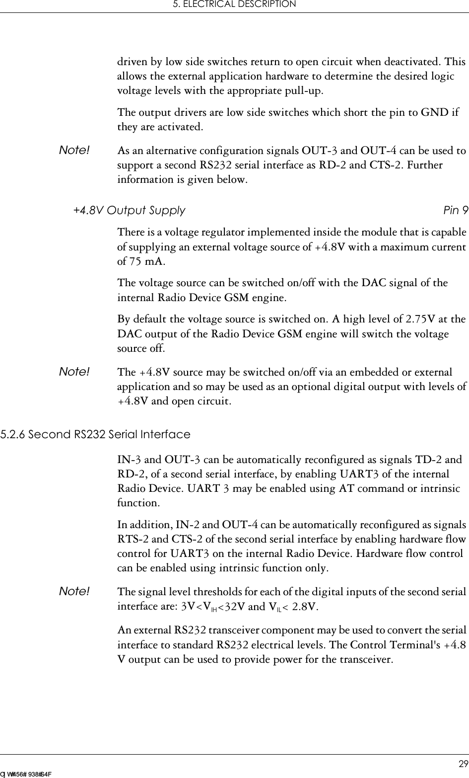
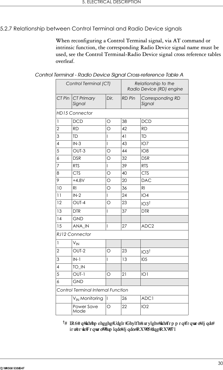
![5. ELECTRICAL DESCRIPTION32LZ T 123 7605 P1CAudio signal descriptions are listed below:MICP and MICN are balanced differential microphone input signals. These inputs are compatible with an electret microphone.BEARP and BEARN are the speaker output signals. These are differential-mode outputs. The electrical characteristics are given in the table below.The following table shows the ear piece impedances that can be connected to BEARP and BEARN.Pin Signal Dir Description1MICN IMicrophone negative input2 BEARN O Earpiece negative output3BEARP OEarpiece positive output4 MICP I Microphone positive inputParameter LimitOutput level (differential) ≥4.0VppOutput level (dynamic load = 32Ω)≥2.8VppDistortion at 1kHz and maximum output level ≤5%Offset, BEARP to BEARN ±30mVEar piece mute switch attenuation ≥40dBEar piece model Impedance ToleranceDynamic ear piece [32Ω + 800µH] // 100pF ±20%Dynamic ear piece [150Ω + 800µH] // 100pF ±20%Piezo ear piece 1kΩ + 60nF ±20%](https://usermanual.wiki/Sony/6220512.Integrators-Manual/User-Guide-369929-Page-32.png)
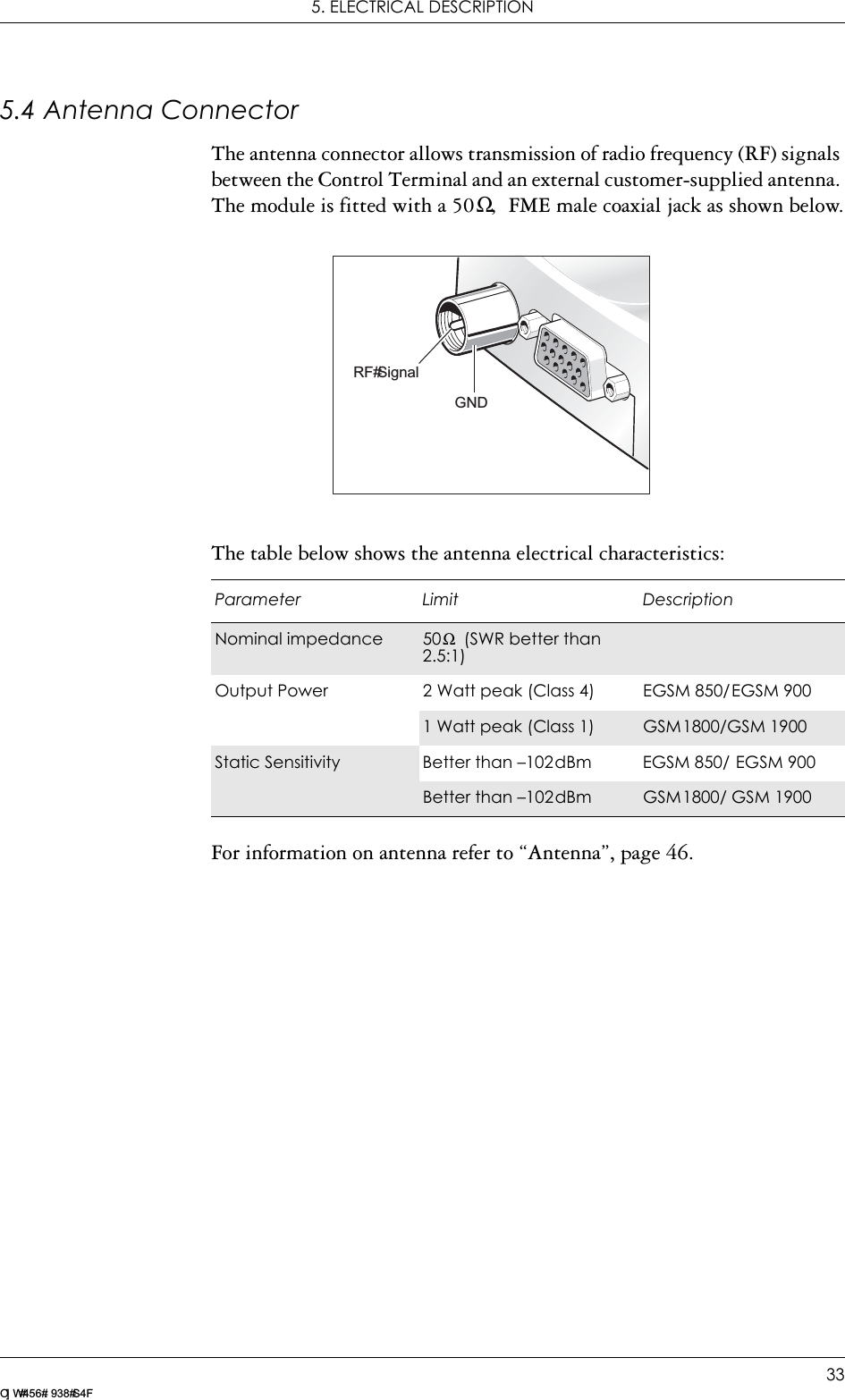
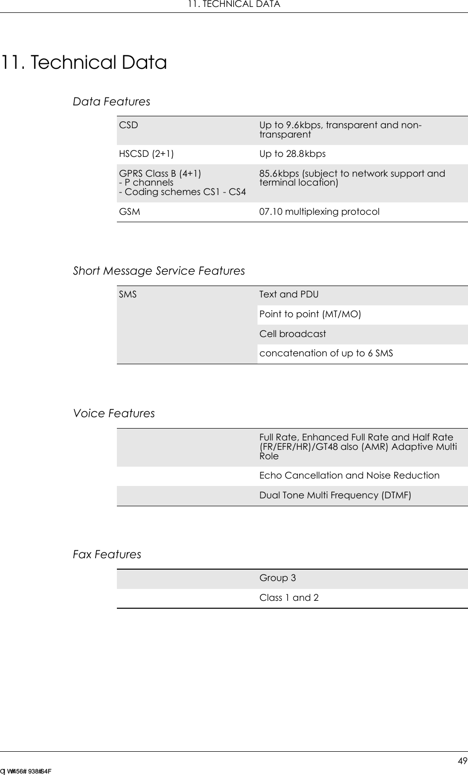
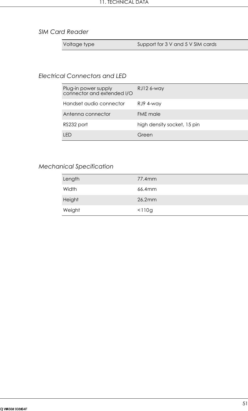
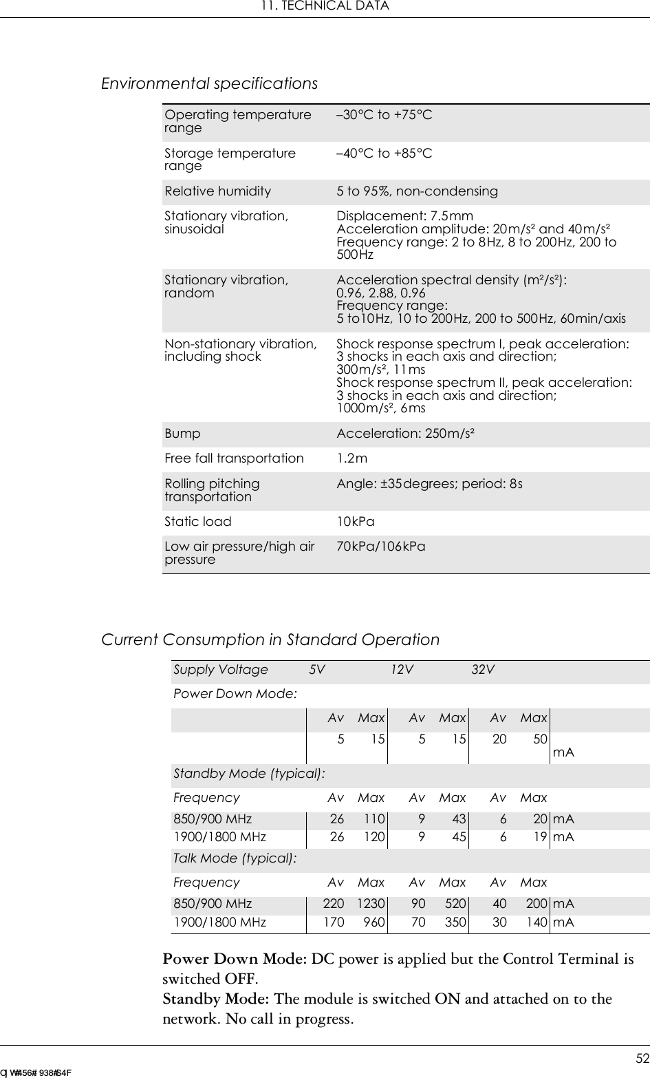
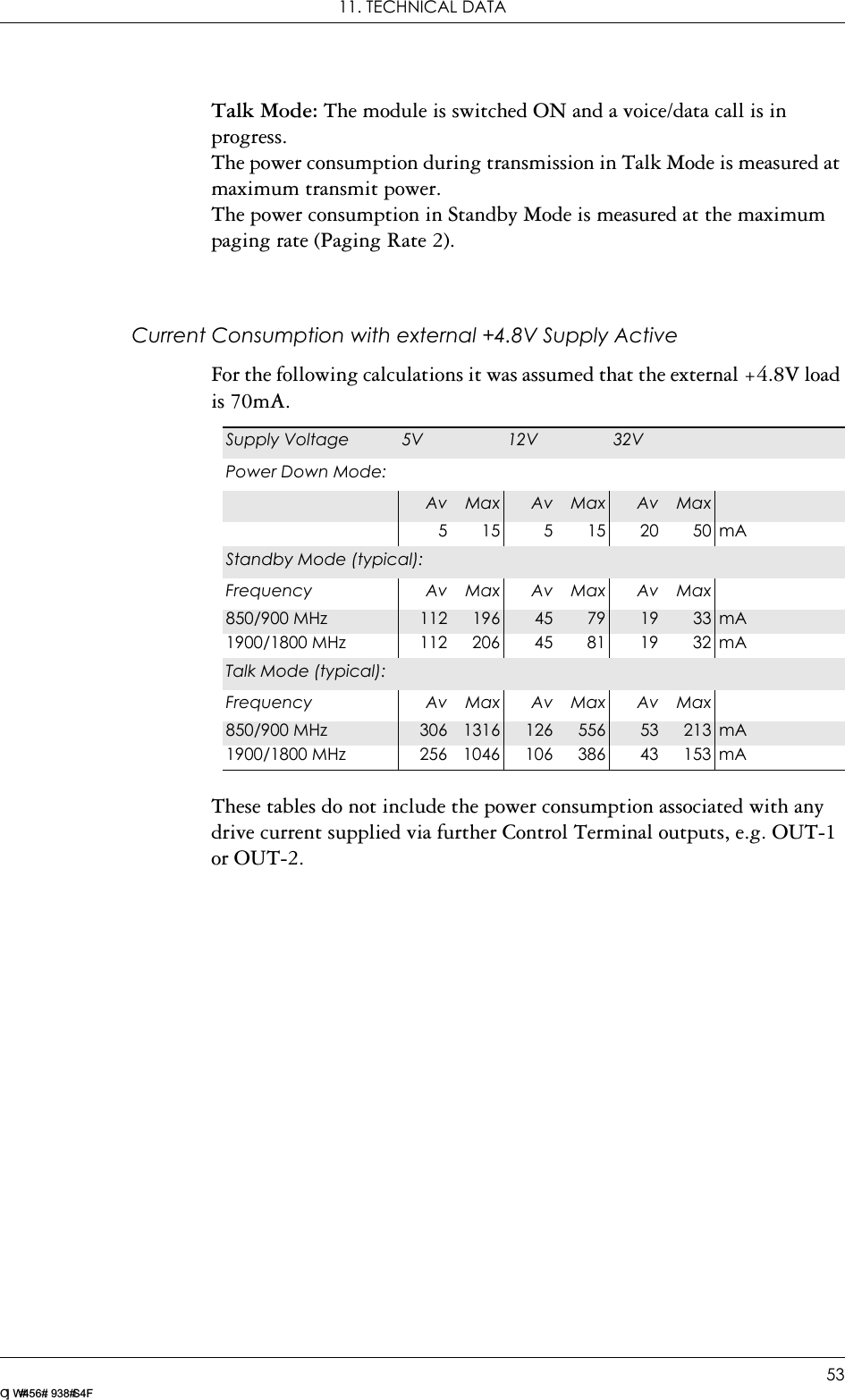
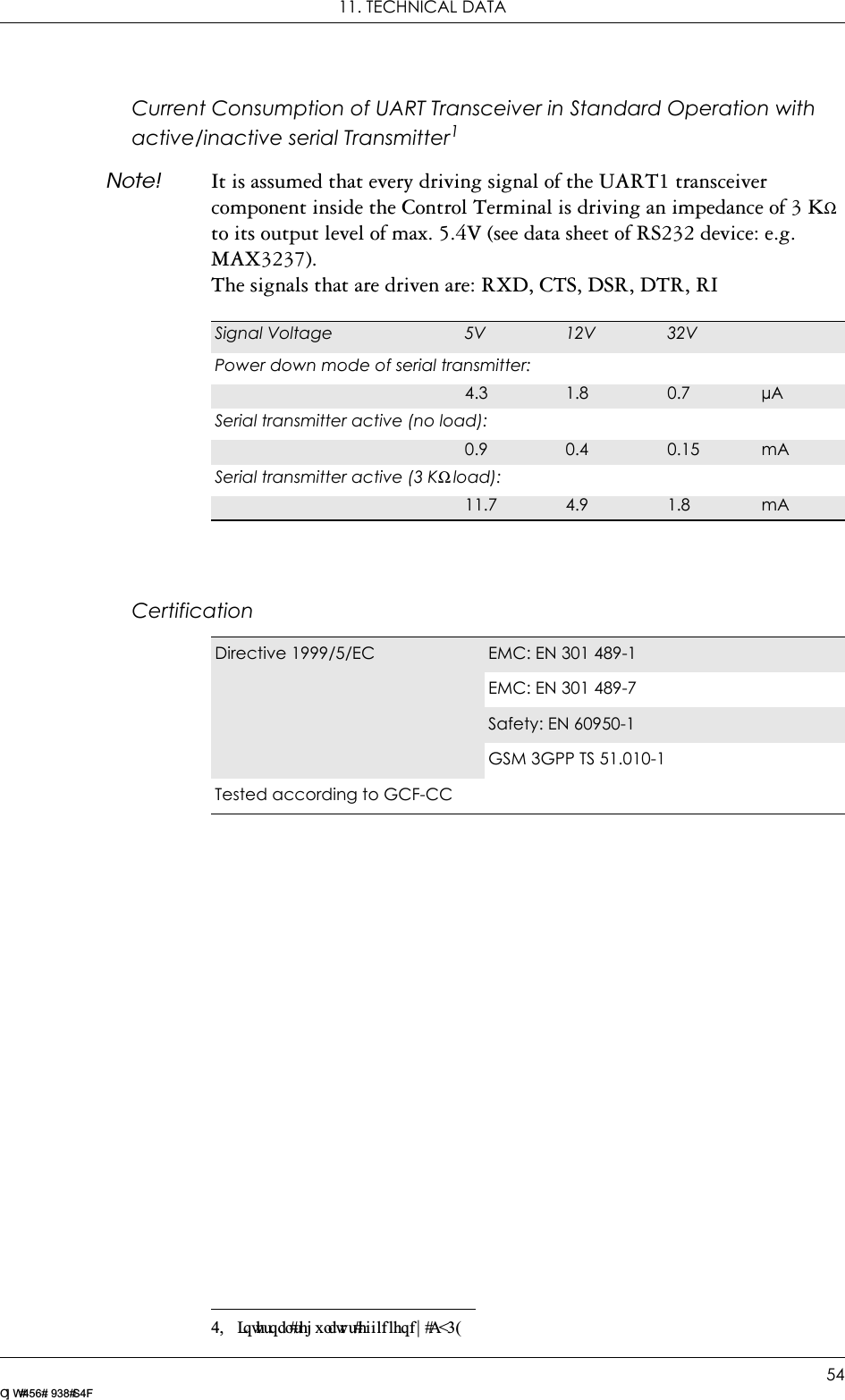
![11. TECHNICAL DATA50LZ T 123 7605 P1CData StoragePower SupplyRadio SpecificationsAudio SpecificationsSMS storage capacity 40 in the moduleIn addition, the unit can handle as many SMS as the SIM can storePhone book capacity 100Supply voltage range 5 to 32V d.c.Frequency bands GT47: EGSM 900 and GSM 1800 (dual band)GT48: GSM 850 and GSM 1900 (dual band)Maximum RF output power2W (EGSM 900/GSM 1800)1W (GSM 850/GSM 1900)Antenna impedance 50Ω Static sensitivity Better than –102dBmParameter LimitOutput level (differential) ≥4.0VppOutput level (dynamic load = 32Ω)≥2.8VppDistortion at 1kHz and maximum output level ≤5%Offset, BEARP to BEARN ±30mVEar-piece mute-switch attenuation ≥40dBEar piece model Impedance ToleranceDynamic ear piece [32Ω + 800µH] // 100pF ±20%Dynamic ear piece [150Ω + 800µH] // 100pF ±20%Piezo ear piece 1kΩ + 60nF ±20%](https://usermanual.wiki/Sony/6220512.Integrators-Manual/User-Guide-369929-Page-50.png)