SmartThings F-USB-US-V1 Extend USB Stick User Manual
SmartThings, Inc. Extend USB Stick Users Manual
UserManual.wiki
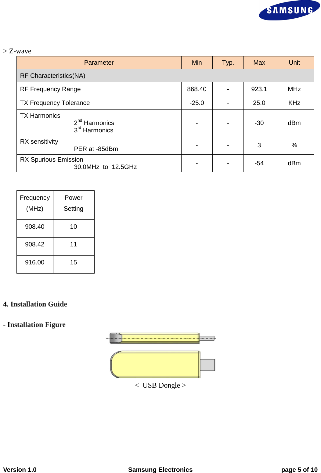
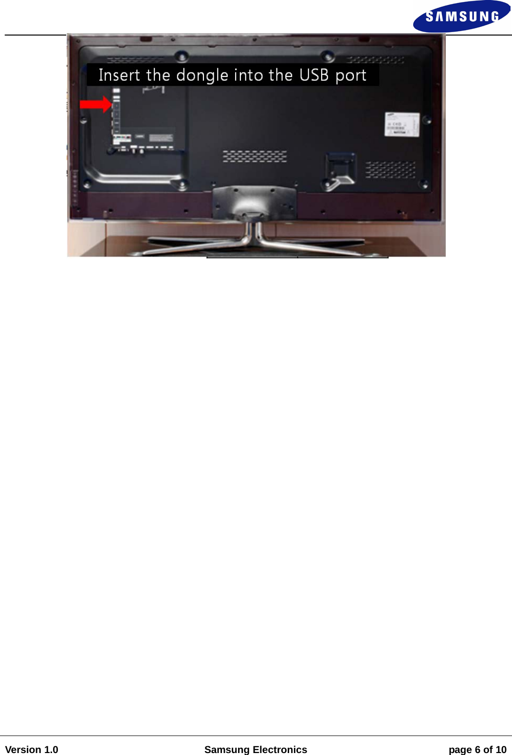
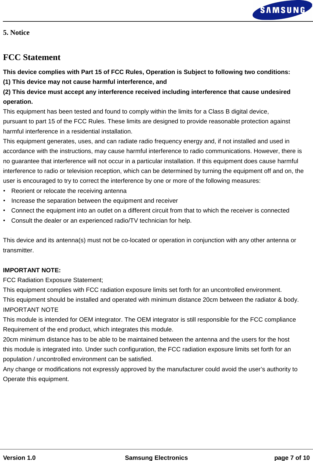
>
SmartThings
>
F-USB-US-V1 User Manual
>
Users Manual
Contents
1.
Users Manual
2.
manual
Users Manual
Navigation menu
Upload a User Manual
Namespaces
Wiki Guide
HTML
PDF
Info
Views
User Manual
Discussion / Help
Navigation