Silicon Storage Technology SST18SC03 MelodyWing SP User Manual

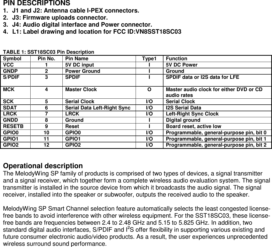
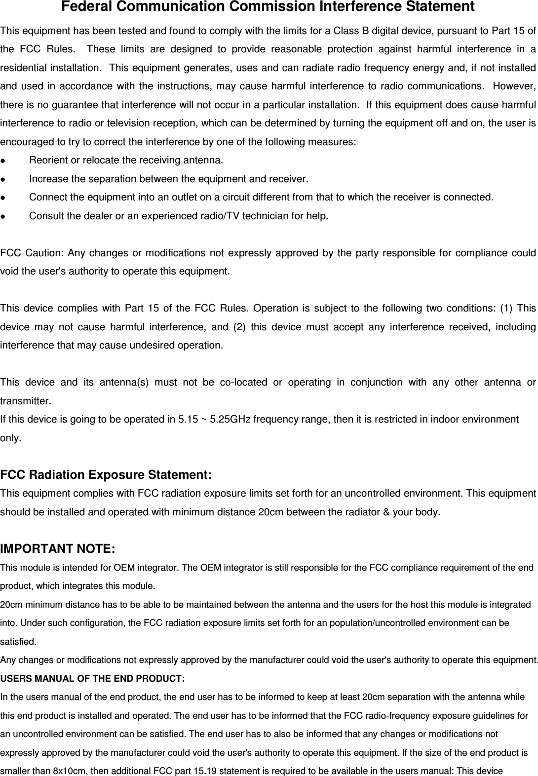
Silicon Storage Technology, Inc. MelodyWing SP Users Manual

Users Manual

MelodyWing SP Quick Installation Guide  FEATURES: • Supports S/PDIF and I2S Digital Audio Interfaces • Supports up to Two Full-range Speakers and a Subwoofer, per Transmitter • Factory-programmable, World-wide, License-free Bands. – 2.4 - 2.48 GHz, 5.15 - 5.825 GHz – Allows one product design to meet requirements for multiple markets • Smart Channel Selection – Automatically avoids interference with other wireless equipment in the home • User-friendly Solution Requires No Firmware Drivers or Setup • RF Performance – 20 MHz Channel Spacing – Receiver Sensitivity TBD dBm at 0.001% BER – Transmitter Output Power TBD dBm max depending on regulatory requirement – Distance up to 20m in the same room, extendable to >20m for multiple rooms • Audio Interface – 1 port S/PDIF, compliant to AC-3, DTS, MP3, AAC, and PCM – 2 ports of I2S - Stereo - Low Frequency Enhancement (LFE) • User Interface, 3 ports GPIO, 1 UART • Security 6 Bytes (48 bits) of IEEE 802.3-like MAC address • Supply Voltage 5V • DC Power – 230 mA average operating current • Audio Quality – Pulse-code Modulation (PCM) bits - Up to 24-bits per channel for stereo, compatible with 16-bits stereo – Accepts 32, 44.1, 48, 88.2, 96, 192 kHz sampling rates – Less than one audio sample, or 22 µs, delays between independent left and right receivers – Programmable, End-to-End Delay, 1 ms up to 80 ms • Operating Temperature – 0ºC to +85ºC • Packages Available – Exposed board • All non-Pb (lead-free) devices are RoHS compliant  APPLICATIONS: • Digital Television, HDTV • Home Theater Systems • Projector • Music Streaming • Headset • Multimedia PC • Game Console • Sound Bar • DVD Players • Cable/Satellite Set-top Boxes
PRODUCT DESCRIPTION MelodyWing™ SP is an advanced wireless audio solution offering uncompressed, wire-equivalent sound quality. This sound quality provides the capacity to wirelessly stream high quality sound independently to two full-range speakers and a subwoofer. In the 2.4 and 5 GHz, dual-band system option, the SST18SC03 utilizes digital audio interfaces to provide high-quality sound.  INSTALLATION DIAGRAM Modules install 1  Modules install 2
FUNCTIONAL BLOCKS  FIGURE 1: Functional Block Diagram for Single-Link 2.1 System    FIGURE 2: Functional Block Diagram for Triple-Link 2.1 System
 FIGURE 3: Functional Block Diagram for Hextuple-Link 5.1 System  PIN ASSIGNMENTS  FIGURE 4: Pin Assignments for SST18SC03
PIN DESCRIPTIONS 1.  J1 and J2: Antenna cable I-PEX connectors. 2.  J3: Firmware uploads connector. 3.  J4: Audio digital interface and Power connector. 4.  L1: Label drawing and location for FCC ID:VN8SST18SC03   TABLE 1: SST18SC03 Pin Description Symbol  Pin No.  Pin Name   Type1  Function   VCC  1  5V DC input  I  5V DC Power   GNDP  2  Power Ground  I  Ground   S/PDIF  3  SPDIF  I  SPDIF data or I2S data for LFE   MCK  4  Master Clock  O  Master audio clock for either DVD or CD audio rates  SCK  5  Serial Clock  I/O  Serial Clock   SDAT  6  Serial Data Left-Right Sync  I/O  I2S Serial Data   LRCK  7  LRCK  I/O  Left-Right Sync Clock   GNDD  8  Ground  I  Digital ground   RESETB  9  Reset  I  Board reset, active low   GPIO0  10  GPIO0  I/O  Programmable, general-purpose pin, bit 0   GPIO1  11  GPIO1  I/O  Programmable, general-purpose pin, bit 1   GPIO2  12  GPIO2  I/O  Programmable, general-purpose pin, bit 2     Operational description The MelodyWing SP family of products is comprised of two types of devices, a signal transmitter and a signal receiver, which together form a complete wireless audio evaluation system. The signal transmitter is installed in the source device from which it broadcasts the audio signal. The signal receiver, installed into the speaker or subwoofer, outputs the received audio to the speaker.  MelodyWing SP Smart Channel selection feature automatically selects the least congested license-free bands to avoid interference with other wireless equipment. For the SST18SC03, these license-free bands are frequencies between 2.4 to 2.48 GHz and 5.15 to 5.825 GHz. In addition, two standard digital audio interfaces, S/PDIF and I2S offer flexibility in supporting various existing and future consumer electronic audio/video products. As a result, the user experiences unprecedented wireless surround sound performance.
Federal Communication Commission Interference Statement This equipment has been tested and found to comply with the limits for a Class B digital device, pursuant to Part 15 of the  FCC  Rules.    These  limits  are  designed  to  provide  reasonable  protection  against  harmful  interference  in  a residential installation.  This equipment generates, uses and can radiate radio frequency energy and, if not installed and used in accordance with the instructions, may cause harmful interference to radio communications.  However, there is no guarantee that interference will not occur in a particular installation.  If this equipment does cause harmful interference to radio or television reception, which can be determined by turning the equipment off and on, the user is encouraged to try to correct the interference by one of the following measures:  Reorient or relocate the receiving antenna.  Increase the separation between the equipment and receiver.  Connect the equipment into an outlet on a circuit different from that to which the receiver is connected.  Consult the dealer or an experienced radio/TV technician for help.  FCC Caution: Any changes or modifications not expressly approved by the party responsible for compliance could void the user's authority to operate this equipment.  This device complies  with Part 15  of the FCC  Rules. Operation is subject to the following two conditions: (1) This device  may  not  cause  harmful  interference,  and  (2)  this  device  must  accept  any  interference  received,  including interference that may cause undesired operation.  This  device  and  its  antenna(s)  must  not  be  co-located  or  operating  in  conjunction  with  any  other  antenna  or transmitter. If this device is going to be operated in 5.15 ~ 5.25GHz frequency range, then it is restricted in indoor environment only.  FCC Radiation Exposure Statement: This equipment complies with FCC radiation exposure limits set forth for an uncontrolled environment. This equipment should be installed and operated with minimum distance 20cm between the radiator & your body.  IMPORTANT NOTE: This module is intended for OEM integrator. The OEM integrator is still responsible for the FCC compliance requirement of the end product, which integrates this module. 20cm minimum distance has to be able to be maintained between the antenna and the users for the host this module is integrated into. Under such configuration, the FCC radiation exposure limits set forth for an population/uncontrolled environment can be satisfied.  Any changes or modifications not expressly approved by the manufacturer could void the user's authority to operate this equipment. USERS MANUAL OF THE END PRODUCT: In the users manual of the end product, the end user has to be informed to keep at least 20cm separation with the antenna while this end product is installed and operated. The end user has to be informed that the FCC radio-frequency exposure guidelines for an uncontrolled environment can be satisfied. The end user has to also be informed that any changes or modifications not expressly approved by the manufacturer could void the user's authority to operate this equipment. If the size of the end product is smaller than 8x10cm, then additional FCC part 15.19 statement is required to be available in the users manual: This device
complies with Part 15 of FCC rules. Operation is subject to the following two conditions: (1) this device may not cause harmful interference and (2) this device must accept any interference received, including interference that may cause undesired operation. LABEL OF THE END PRODUCT: The final end product must be labeled in a visible area with the following " Contains TX FCC ID:VN8SST18SC03 ". If the size of the end product is larger than 8x10cm, then the following FCC part 15.19 statement has to also be available on the label:  This device complies with Part 15 of FCC rules. Operation is subject to the following two conditions: (1) this device may not cause harmful interference and (2) this device must accept any interference received, including interference that may cause undesired operation.

Navigation menu