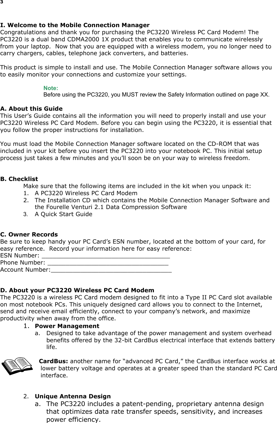
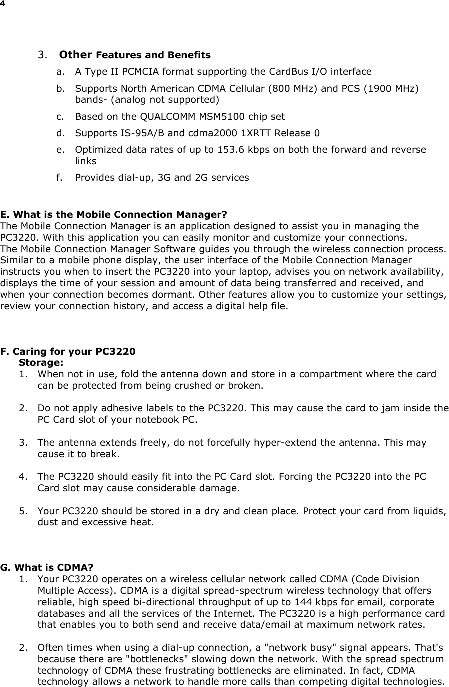
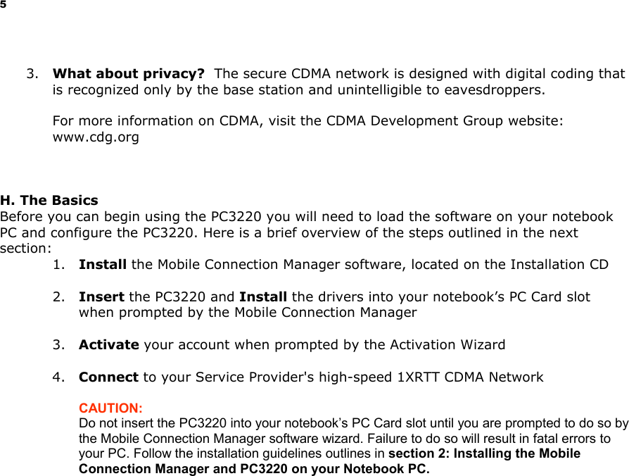
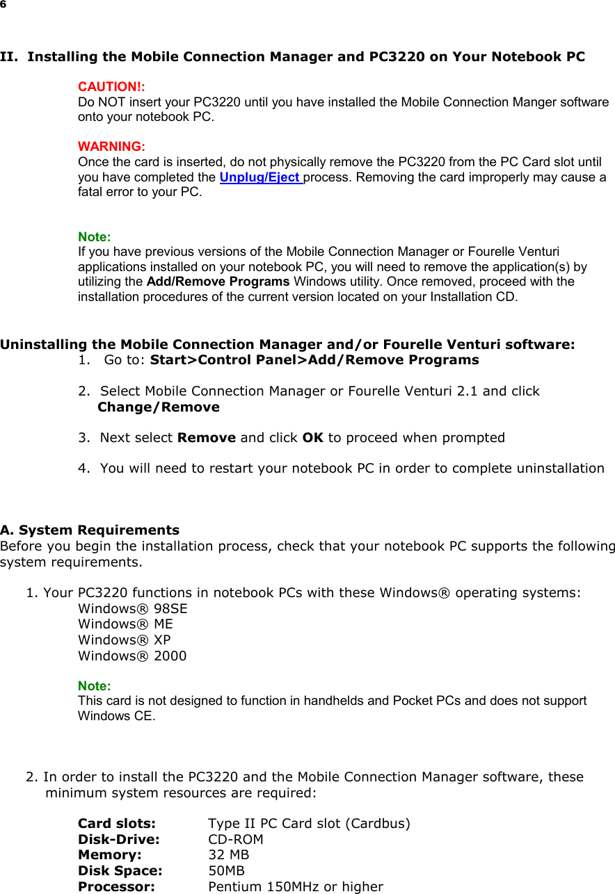
Sierra Wireless PC3220P Dual-Band CDMA PCMCIA Modem Card User Manual 1 per CRN 24858
Sierra Wireless, Inc Dual-Band CDMA PCMCIA Modem Card Users Manual 1 per CRN 24858
Contents
- 1. Users Manual
- 2. Users Manual 1 per CRN 24858
- 3. Users Manual 2 per CRN 24858
- 4. Users Manual per CRN 24959
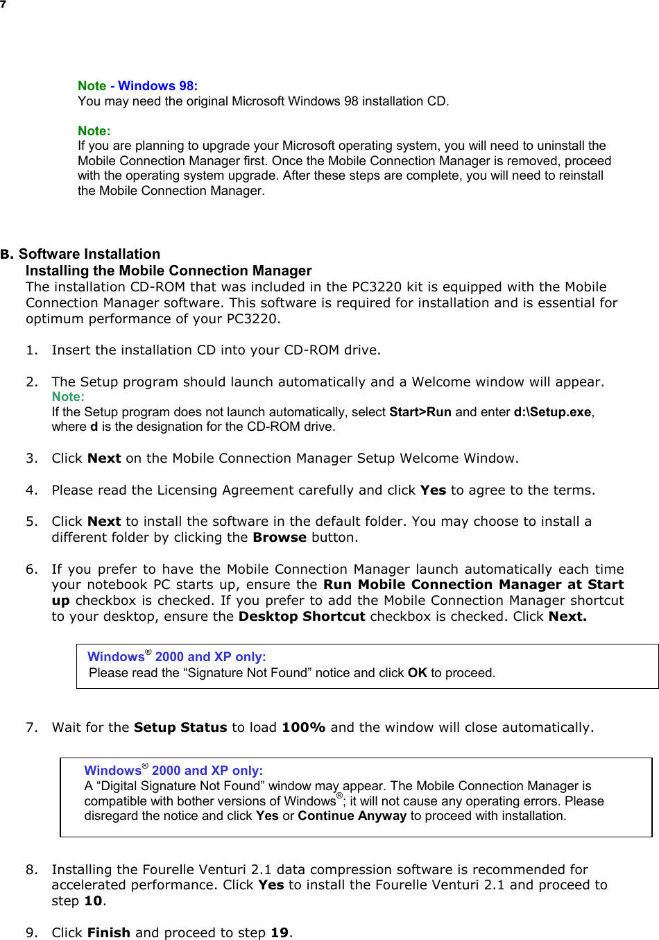
Users Manual 1 per CRN 24858
![10 NOTE: You may hear a short beep each time the PC3220 is inserted and removed from your notebook PC. This is normal. It is an audible notification from your notebook PC communicating that it recognizes new hardware. D. Activating the PC3220 1. Auto Activation a. Once the PC3220 is properly inserted into the Type II PC Card slot of your notebook PC, the Activation Wizard will automatically appear. Click Activate. (You will not be able to connect to the network if your PC3220 has not been activated). b. The Activation Progress window displays the status of the activation. Once the procedure is complete, the window will close automatically. c. An “Activation complete” message appears. Click OK to exit the Activation Wizard and wait for your notebook PC to restart automatically. NOTE: If you cancel the Activation Wizard before Activation is complete, an Activation Alert Notification will be displayed explaining that you must activate your card in order to connect to the Internet or other Internet dependent function, such as email. Activation: the process of setting up an account. 2. Troubleshooting: Activation FIG 2 [FILE NAME: CIRCLE X.BMP] a. If you receive an "Activation Unsuccessful" message when you attempt to activate the PC3220 through Auto Activation follow these steps to initiate Manual Activation: 3. Manual Activation a. Contact your Service Provider for an Activation Code, Phone Number and SID (System Identifier). Activation Code: _________________________________ Phone Number: __________________________________ SID: ___________________________________________ b. Select Manual Activation from the Activation Unsuccessful alert window. c. A four-step Activation Wizard appears. Follow the on-screen instructions and click Finish when complete.](https://usermanual.wiki/Sierra-Wireless/PC3220P.Users-Manual-1-per-CRN-24858/User-Guide-308362-Page-10.png)
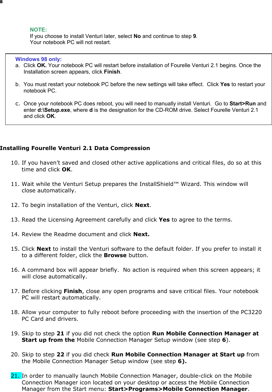
![11 d. Once you have properly inserted the PC3220 into your notebook PC’s Type II PC Card slot, the Mobile Connection Manager will notify that it is ready to connect to the network (See page XX). e. Select your network connection profile from the pull down and then click Connect in order to activate a session. (See XX for more information on Network Connection Profiles). Service Provider: a company that operates and provides access to CDMA networks. In order to connect to the Internet with your PC3220, you must have an account with a CDMA service provider. Fig 3 [File Name: UI_menu callout.bmp; OR UI_menu.bmp] NOTE: If you have not activated your PC3220, an Activation Alert Notification will be displayed once you click the Connect button explaining that you must activate your card in order to establish a session. 4. Establishing a Connection after Activation The Mobile Connection Manager will take a few moments to connect to the network. The word Connected appears in the Indicator Area notifying you that a connection has been established. (The Connect button will change to read Disconnect.) Fig 4 [File Name: UI_Connected.bmp] 5. To disconnect from the network and end your current connection, click Disconnect. NOTE: "No Service" message is displayed when the PC3220 cannot locate the network. "Connected" message is displayed once a connection is established. Connection Profiles Pull-down Menu](https://usermanual.wiki/Sierra-Wireless/PC3220P.Users-Manual-1-per-CRN-24858/User-Guide-308362-Page-11.png)
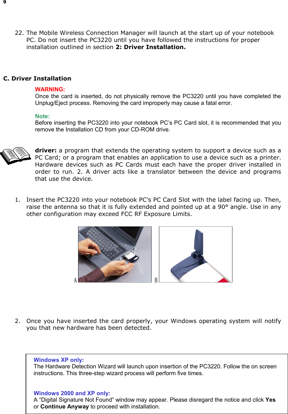
![12 6. The dialog box will return to the “Ready state” to notify you that your session is no longer active. 7. To “power-off” the Mobile Connection Manager, click on the icon found in your system tray. Fig 5. [File Name: ST_shortcut menu_power.bmp; OR systemtray.bmp; OR powermenu.bmp] WARNING: Do not eject the PC3220 from your notebook until you have followed the instructions for proper removal. Removing the card improperly may cause a fatal error. E. Removing the PC3220 from your Notebook PC 1. Click on the “Mobile Connection Manager” icon found in the system tray. Fig 6 [File Name: MCM_icon.bmp] 2. Select Exit from the menu. (The icon will disappear from the system tray). 3. After the Mobile Connection Manager has exited, go to the system tray and click on the “Unplug and Eject Hardware” icon. Fig 7 [File Name: WIN98 Eject.bmp; WINXP Eject.bmp; WIN2KME Eject.bmp] 4. Select “AirPrime USB Open Host Controller” from the Unplug/Eject Hardware window. Next, click Stop and then Close. 5. A Stop Hardware Device window pops up, asking to confirm which device to stop. Select “AirPrime USB Open Host Controller” and click OK. 6. After the “Safe to Remove Hardware” message appears, click OK. 7. You may now remove the PC3220 from your notebook. When removing the PC3220, always grip it by the sides of the card rather than from the top. Pulling on the antenna over time may damage the card. If available, use the Card Ejector tool on your laptop. System Tray Icon Windows 2000 & ME Windows XP Windows 98SE](https://usermanual.wiki/Sierra-Wireless/PC3220P.Users-Manual-1-per-CRN-24858/User-Guide-308362-Page-12.png)
![13 F. Establishing a Connection 1. Once you have properly inserted the PC3220 into your notebook PC's Type II PC Card slot (See Installing the Drivers to your Notebook PC), the Mobile Connection Manager will notify that it is ready to connect to the network. Fig 8 [File Name: genericUI-Ready1.bmp] 2. Select your network connection preference from the pull down menu and then click Connect in order to establish a connection. Fig 9: [File Name: genericUI_ComboBoxOPen1.bmp] 3. The Mobile Connection Manager will take a few moments to connect to the network. The dialog box at the bottom of the Mobile Connection Manager window will display the word Connected to notify that you have established a connection. The Connect button will change to read Disconnect. To end the connection, click Disconnect. Fig 10 [File Name: UI_connected.bmp] Connection Profiles Pull-down Menu](https://usermanual.wiki/Sierra-Wireless/PC3220P.Users-Manual-1-per-CRN-24858/User-Guide-308362-Page-13.png)
![14 4. To end the connection, click Disconnect. 5. Once you have ended your connection, the dialog box will return to the "Ready" state. Fig 11 [File Name: genericUI-Ready1.bmp] Note: " No Service" message is displayed when the PC3220 cannot locate the network. "Connected" message is displayed once a connection is established. 6. In order to Power Off the Mobile Connection Manager click on the System Tray Icon and the System Tray Menu will appear. Select Power Off Card. In order to Power on the Mobile Connection Manager, click Power On Card. Fig 12 [File Name: ST_shortcut menu_power.bmp; OR systemtray.bmp; OR powermenu.bmp] WARNING: Do not eject the PC3220 from your notebook until you have followed the Unplug/Eject Hardware instructions for proper removal. Removing the card improperly may cause a fatal error to your PC. G. Exiting the Mobile Connection Manager (MCM) 1. When you have completed your current session, click Disconnect on the Mobile Connection Manager to ensure that you are disconnected from the network; this will make the data connection inactive. 2. Next, click on the Mobile Connection Manager icon located in the system tray of your notebook PC and select Exit from the shortcut menu. This will close the Mobile Connection Manager and the icon will disappear from the system tray. System Tray Icon](https://usermanual.wiki/Sierra-Wireless/PC3220P.Users-Manual-1-per-CRN-24858/User-Guide-308362-Page-14.png)
![15 III. Using the Mobile Connection Manager My Mobile Connection Manager The Mobile Connection Manager is turned on automatically when your laptop starts up, unless you turned this option “off” in the previous section, Software Installation. This view of the Mobile Connection is called Full Mode. An alternate view, called the System Tray Mode, is described later in this section, titled: System Tray Mode (Connection Status Icon and Menu). Fig 13 [File Name: generic_Indicator_Area_Callout1.bmp] Full Mode: A. Understanding The Indicator Area and Icons Depending on the PC3220’s operating mode, different indicators will be displayed. Fig 14 [File Name: generic_Indicator_Area_Callout2.bmp] Close (System Tray)](https://usermanual.wiki/Sierra-Wireless/PC3220P.Users-Manual-1-per-CRN-24858/User-Guide-308362-Page-15.png)
![16 1. Signal Strength Indicator Fig 15 [ File Name: Icon_Signal Strength.bmp] The Signal Strength icon displays when the Mobile Connection Manager is turned on. The bars indicate the strength of the radio signal. Four bars signify that the signal strength is at its maximum peak. The strength will change depending on where you are. Fig 16 [File Name: Icon_Signal Strength red.bmp] This displays when no signal is available or when the Mobile Connection Manager is turned off. The antenna symbol is red and the bars are dimmed. When this occurs, no connection is possible for one of the following reasons: • You are outside of a CDMA network coverage area • The signal strength is too weak • A network problem is preventing the PC3220 from obtaining service • The Mobile Connection Manager is not turned on or the PC3220 has not been inserted • The antenna is not raised to a 90° angle 2. Service Indicator Fig 17: [File Name: Icon_Service Indicator.bmp] Fig 18: [File Name: Icon_2G.bmp] Fig 19: [File Name: Icon_Service Indicator.bmp] Fig 20: [File Name: Icon_2G.bmp] Fig 21: [File Name: Icon_3Gdimmed.bmp] or The Service Indicator icon displays which network service is currently available at your location, the 3G Network or the 2G Network. 3G Connection This default icon signifies that the 3G network is available (even if 2G is also available) 2G Connection This icon signifies that only the 2G network is available Note: The 3G icon will appear even if the 2G network is also available. You are able to make data calls on the 3G network, if your billing plan allows for it. (Depending on your billing plan, there may an additional charge for data calls on the 3G network. Contact your service provider for more information on accessing 3G.) data call: similar to making a voice call, a data call is the term used when you access the Internet. Data calls go dormant when the Internet activity is inactive for ~30 seconds. When a data call goes dormant, you are not being charged for airtime. No service The icon is dimmed when no service is available](https://usermanual.wiki/Sierra-Wireless/PC3220P.Users-Manual-1-per-CRN-24858/User-Guide-308362-Page-16.png)
![17 3. Data Compression Fig 22: [File Name: Icon_Compression Indicator.bmp] Fig 23: [File Name: Icon_Compress_gray.bmp] The Data Compression icon appears when the Fourelle Venturi 2.1 data compression tool is active. When the Data Compression icon is dimmed, the Fourelle Venturi 2.1 application is inactive. 4. Roaming Status Fig 23: [File Name: generic_icon roam1.bmp] Fig 24: [File Name: generic_icon roam1.bmp] Fig 25: [File Name: generic_Icon roam0.bmp] The Roaming Status icon indicates the roaming status of your PC3220. When you are roaming, you are using the network of another service provider that offers coverage outside of your local coverage area. This typically happens when you are out of your coverage area. When the indicator is “on” (solid black) you are roaming within a “preferred” roaming area. When the icon is blinking, you are roaming within a CDMA network, but not in a “preferred” zone. When the indicator is “off” (dimmed), you are within the local coverage area of your service provider. You are not roaming. Note: Your coverage area and billing charges depend upon your service provider and the type of account you have. There may be surcharges for roaming service that varies based on whether you are in a preferred roaming area or a non-preferred roaming area. If there is no roaming agreement between your service provider and the local carrier, you may be unable to complete calls in a non-preferred zone. 5. Connection Indicator Fig 26: [File name: Icon_Compression Indicator.bmp] Fig 27: [File name: Icon_Connection Indicator dimmed.bmp] The Connection Indicator icon signifies that a connection is established. The icon will flash while you are in the process of connecting and will then remain static once you are connected. If the Connection Indicator icon is dimmed, there is no connection nor is a connection attempt in process.](https://usermanual.wiki/Sierra-Wireless/PC3220P.Users-Manual-1-per-CRN-24858/User-Guide-308362-Page-17.png)
![18 6. Connection Time The Connection Time field displays the duration of the current data call or connection. The timer begins as soon as a connection is established. The time format is 00hrs: 00min: 00sec. 7. Byte Counter The Byte Counter displays the amount of data transferred and received during as soon as a connection is established in measurements of Kilobytes and Megabytes. For 0 to 999KB: “XXX KB” format (I.e., “7 KB,” “68 KB,” or “768 KB”) For 1MB and up: “XXX.X MB” format (I.e., “1.0 MB,” “3.2 MB” or “343.3 MB”) 8. Service Status Dialog Box The Service Status Dialog Box explains the current status of your PC3220. Fig 28: [File Name: Icon_Service Indicator.bmp] Fig 29: [File Name: Icon_2G.bmp] Fig 30: [File Name: Icon_3G dimmed.bmp] Fig 31: [File Name: Icon_Connection Indicator.bmp] Fig 32: [File Name: Icon_Connection Indicator dimmed.bmp] Fig 33: [File Name: Icon_Connection Indicator.bmp Service Status Dialog Description Associated icon graphic Please insert Card No card is detected The system tray icon displays gray Card is Off PC Card is powered off The system tray icon displays gray Ready Service is available or appear in the Indicator area and the system tray icon displays green No Service No service is available This icon will be gray Connecting Attempting to make a connection This icon will flash Connected A connection is established (2G, 3G active or dormant) Dormant/Connected A connection is established but no data transfer is in progress The system tray icon displays yellow Disconnecting Disconnecting the current call None Call Dropped Call is dropped; transient state returning to Ready None](https://usermanual.wiki/Sierra-Wireless/PC3220P.Users-Manual-1-per-CRN-24858/User-Guide-308362-Page-18.png)
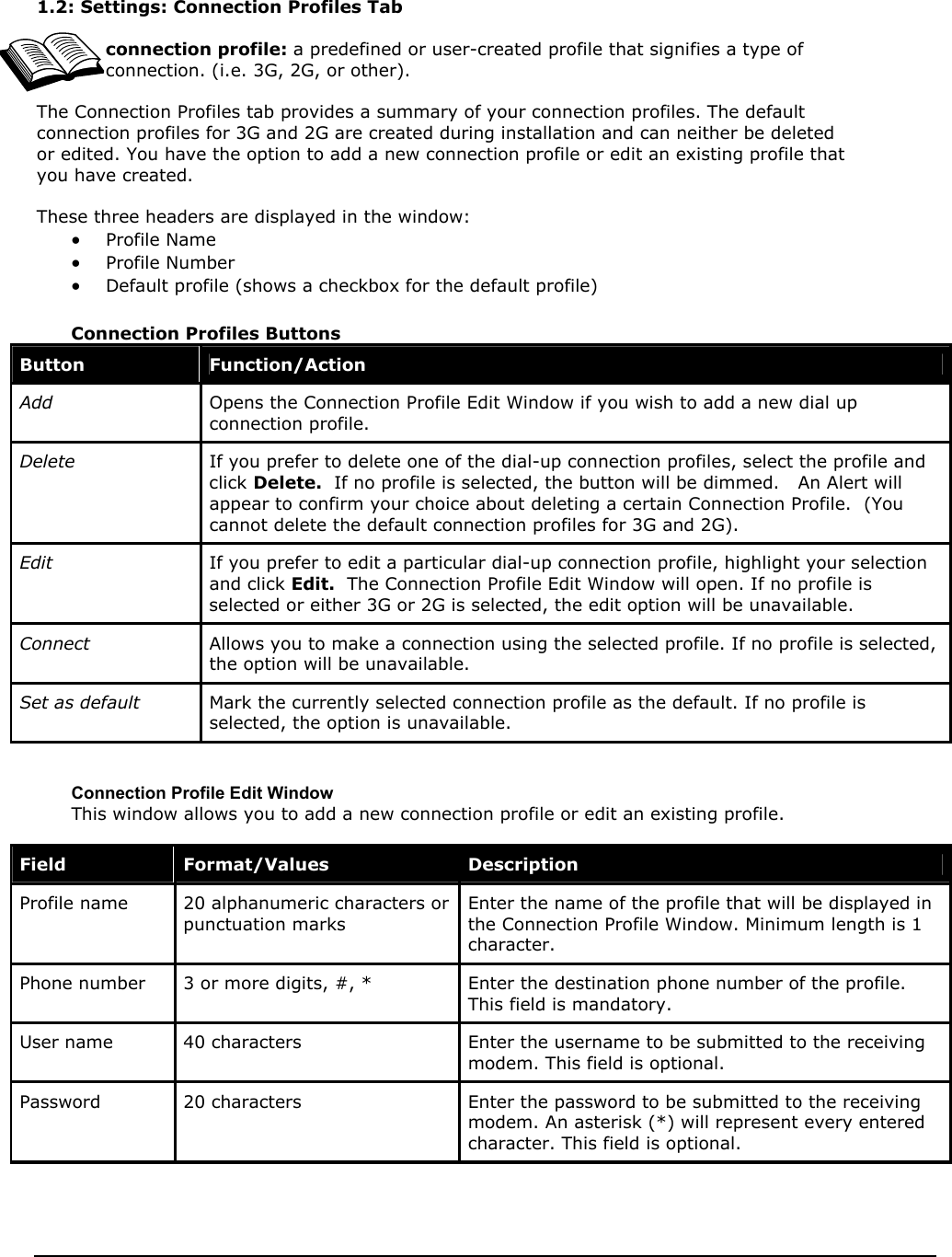
![B. Understanding the Action Buttons The Action Buttons allow you to customize the Mobile Connection Manager and monitor your connections. Fig 34: [File Name: genericUI-action circle.bmp] 1. Settings The Settings tool allows you to customize the Mobile Connection Manager. Once you click on this button a pop-up window with three tabs will appear: General Connection Profiles About 1.1 Settings: General Tab Option Choices Description Enable Compression - On - Off (default) This option is turned "off" by default. If you prefer to set the Fourelle Venturi 2.1 data compression to remain "on" place a checkmark in the checkbox. Start in System Tray Mode - In Full Mode (default) - In System Tray Mode None of these options allow automatic placement of a data call upon card insertion. Run Mobile Connection Manager at Start up - On (default) - Off This default setting can be changed during installation. Refer to Installing the Mobile Connection Manager, step 5. Enable Call Drop Alert - On (default) - Off This option is checked by default. It enables a pop-up window and audible alert when the connection is dropped. Applicable to 2G and Dial-up Networking only. Premium Service Alert - On (default) - Off This option is checked by default and it enables a pop-up window before making a connection to the 3G network.](https://usermanual.wiki/Sierra-Wireless/PC3220P.Users-Manual-1-per-CRN-24858/User-Guide-308362-Page-19.png)
![4. System Tray Shortcut Fig [File Name: UI CloseX.bmp] When viewing the Mobile Connection Manager in Full Mode, you have the option to “ close” the window into System Tray Mode. The icon located in the System Tray communicates your connection status similarly to the Service Status dialog in Full Mode. By clicking on this shortcut, you are activating the System Tray Mode. IV. System Tray Mode (Connection Status Icon and Menu) system tray: also known as the “status area,” the system tray is the section to the right of the Start button on your desktop. If you prefer to close the Full Mode view of the Mobile Connection Manager, you can still monitor your connections with the System Tray icon. This section outlines the functions of the System Tray icon and the System Tray shortcut menu. A. System Tray Icon Once the Mobile Connection is launched, an icon will appear in the System Tray of your notebook PC. This icon will change colors, according to the current status of your connection. Once you exit the Mobile Connection Manager, this icon will disappear. “System Tray Icon” Description Icon Color Tool Tip Ready- When the icon displays blue, it is ready to make a connection Mobile Connection Manager: Ready Connecting- currently making a connection icon is flashing Mobile Connection Manager: Connecting Connected- When the icon displays green, a connection is established and data transfer is in progress Mobile Connection Manager: Connected Dormant/Connected- When the icon displays yellow, a connection is established but no data transfer is in progress Mobile Connection Manager: Dormant/Connected No Service- When the icon displays red, the card has no service Mobile Connection Manager: No Service System Tray Icon](https://usermanual.wiki/Sierra-Wireless/PC3220P.Users-Manual-1-per-CRN-24858/User-Guide-308362-Page-22.png)
![If you have purchased this product under a United States Government contract, it shall be subject to restrictions as forth in subparagraph (C)(1)(ii) of Defense Federal Acquisitions Regulations (DFARs) Section 252.227-7013 for Department of Defense contracts, and as set forth in Federal Acquisitions Regulations (FARs) Section 52.227-19 for civilian agency contracts or any successor regulations. If further government regulations apply, it is your responsibility to ensure compliance with such regulations. B. Safety Information This section outlines important liability and safety guidelines concerning your new PC Card. 1. Important Notice Because of the nature of wireless communications, transmission and reception of data can never be guaranteed. Data may be delayed, corrupted (i.e., have errors) or totally be lost. Although significant delays or losses of data are rare when wireless devices such as the PC Card-Model PC3220 CDMA modem are used in a normal manner with a well constructed network, they should not be used in situations where failure to transmit or receive data could result in damage of any kind to the user or another party, including but not limited to personal injury, death or loss of personal property. No responsibility for damages of any kind resulting from delays or errors in data transmitted or received using the PC Card-Model PC3220 CDMA modem, or for failure of the PC Card-Model PC3220 to transmit or receive such data. 2. Safety and Hazards [File Names: explosive.jpg; hospital.jpg; plane.jpg; car.jpg] Blasting Areas and Hospitals Do not operate the PC Card-Model PC3220 in areas where blasting is in progress, where explosive atmospheres may be present, near medical equipment, life support equipment, or any equipment which may be susceptible to any form of radio interference. In such areas the PC Card-Model PC3220 MUST BE POWERED OFF. It can transmit signals that could interfere with this equipment. Aircraft Do not operate the PC Card- Model PC3220 in any aircraft whether the aircraft is on the ground or in flight. In aircraft, the PC Card- Model PC3220 MUST BE POWERED OFF. When operating it can transmit signals that could interfere with various onboard systems. Driving The driver or operator of any vehicle should not operate the PC Card- Model PC3220 while in control of a vehicle. Doing so will detract from the driver or operator’s control and operation of that vehicle. In some jurisdictions, operating such communications devices while in control of a vehicle is an offense.](https://usermanual.wiki/Sierra-Wireless/PC3220P.Users-Manual-1-per-CRN-24858/User-Guide-308362-Page-28.png)