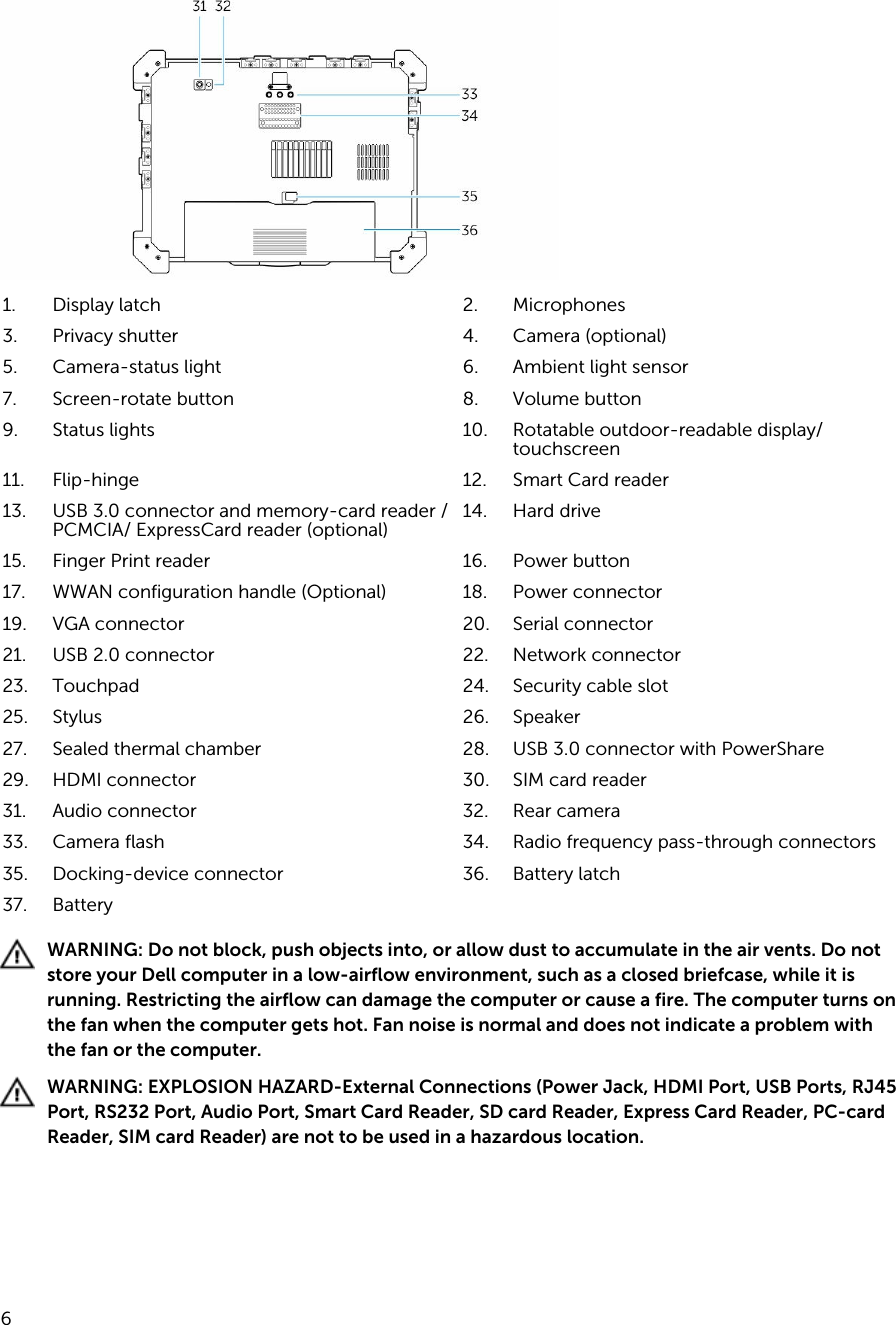
Sierra Wireless EM7355 PCIe wireless WAN card User Manual Getting Started Guide

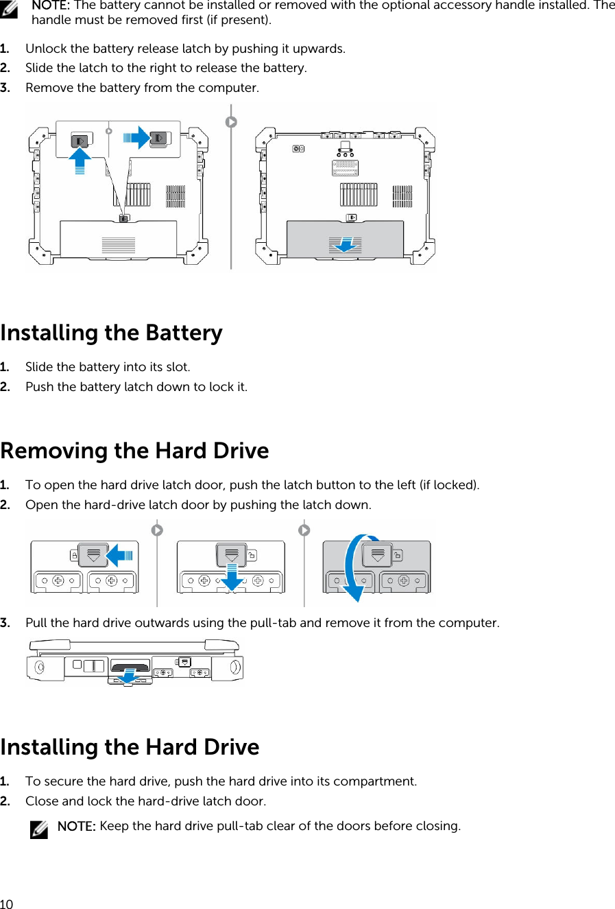
Sierra Wireless Inc. PCIe wireless WAN card Getting Started Guide

Getting Started Guide

Dell Latitude 12 Rugged Extreme (7204)Getting Started GuideRegulatory Model: P18TRegulatory Type: P18T001
Notes, cautions, and warningsNOTE: A NOTE indicates important information that helps you make better use of your computer.CAUTION: A CAUTION indicates either potential damage to hardware or loss of data and tells you how to avoid the problem.WARNING: A WARNING indicates a potential for property damage, personal injury, or death.Copyright © 2015 Dell Inc. All rights reserved. This product is protected by U.S. and international copyright and intellectual property laws. Dell™ and the Dell logo are trademarks of Dell Inc. in the United States and/or other jurisdictions. All other marks and names mentioned herein may be trademarks of their respective companies.2014 - 02Rev. A00
Contents1 Finding Information and Resources.................................................................. 42 System Overview...................................................................................................53 Quick Setup............................................................................................................74 Removing and Installing Components.............................................................9Opening the Press-Latch Doors...........................................................................................................9Closing the Press-Latch Doors.............................................................................................................9Removing the Battery............................................................................................................................9Installing the Battery............................................................................................................................10Removing the Hard Drive....................................................................................................................10Installing the Hard Drive......................................................................................................................105 Working on Your Computer..............................................................................11Using the Backlit Keyboard..................................................................................................................11Turning the Keyboard Backlight On/Off or Adjusting Brightness................................................ 11Changing the Keyboard Backlight Color...................................................................................... 12Customizing the Backlit Keyboard in System Setup (BIOS)......................................................... 12Function <Fn> Key Lock Features.......................................................................................................12Activating the Function (Fn) lock ..................................................................................................13Turning Stealth Mode On/Off............................................................................................................. 13Disabling Stealth Mode in the System Setup (BIOS).......................................................................... 14Enabling and Disabling Wireless (WiFi) Feature..................................................................................14Converting Between Notebook and Tablet Modes .......................................................................... 146 Quick Disconnect (QD) Connector................................................................. 16Installing a QD connector...................................................................................................................16Removing a QD connector.................................................................................................................167 Specifications.......................................................................................................17Information para NOM (únicamente para México)............................................................................218 Contacting Dell...................................................................................................223
1Finding Information and ResourcesSee the safety and regulatory documents that shipped with your computer and the regulatory compliance website at www.dell.com/regulatory_compliance for more information on:• Safety best practices• Regulatory certification• ErgonomicsSee www.dell.com for additional information on:• Warranty• Terms and Conditions (U.S. only)• End User License AgreementAdditional information on your product is available at www.dell.com/support/manuals  4
2System Overview5
1. Display latch 2. Microphones3. Privacy shutter 4. Camera (optional)5. Camera-status light 6. Ambient light sensor7. Screen-rotate button 8. Volume button9. Status lights 10. Rotatable outdoor-readable display/touchscreen 11. Flip-hinge 12. Smart Card reader13. USB 3.0 connector and memory-card reader /PCMCIA/ ExpressCard reader (optional) 14. Hard drive15. Finger Print reader 16. Power button17. WWAN configuration handle (Optional) 18. Power connector19. VGA connector 20. Serial connector21. USB 2.0 connector 22. Network connector23. Touchpad 24. Security cable slot25. Stylus 26. Speaker27. Sealed thermal chamber 28. USB 3.0 connector with PowerShare29. HDMI connector 30. SIM card reader31. Audio connector 32. Rear camera33. Camera flash 34. Radio frequency pass-through connectors35. Docking-device connector 36. Battery latch37. BatteryWARNING: Do not block, push objects into, or allow dust to accumulate in the air vents. Do not store your Dell computer in a low-airflow environment, such as a closed briefcase, while it is running. Restricting the airflow can damage the computer or cause a fire. The computer turns on the fan when the computer gets hot. Fan noise is normal and does not indicate a problem with the fan or the computer.WARNING: EXPLOSION HAZARD-External Connections (Power Jack, HDMI Port, USB Ports, RJ45 Port, RS232 Port, Audio Port, Smart Card Reader, SD card Reader, Express Card Reader, PC-card Reader, SIM card Reader) are not to be used in a hazardous location. 6
3Quick SetupWARNING: Before you begin any of the procedures in this section, read the safety information that shipped with your computer. For additional best practices information, see www.dell.com/regulatory_compliance WARNING: The AC adapter works with electrical outlets worldwide. However, power connectors and power strips vary among countries. Using an incompatible cable or improperly connecting the cable to the power strip or electrical outlet may cause fire or equipment damage.CAUTION: When you disconnect the AC adapter cable from the computer, grasp the connector, not the cable itself, and pull firmly but gently to avoid damaging the cable. When you wrap the AC adapter cable, ensure that you follow the angle of the connector on the AC adapter to avoid damaging the cable.NOTE: Some devices may not be included if you did not order them.1. Connect the AC adapter to the AC adapter connector on the computer and to the electrical outlet.Figure 1. AC Adapter2. Connect the network cable (optional).Figure 2. Network Connector3. Connect USB devices, such as a mouse or keyboard (optional).Figure 3. USB Connector4. Connect IEEE 1394 devices, such as a 1394 hard drive (optional).7
Figure 4. 1394 Connector5. Open the computer display and press the power button to turn on the computer.Figure 5. Power ButtonNOTE: It is recommended that you turn on and shut down your computer at least once before you install any cards or connect the computer to a docking device or other external device, such as a printer. 8
4Removing and Installing ComponentsThis section provides detailed information on how to remove or install the components from your computer.Opening the Press-Latch DoorsThere are six press-latch doors. Three on the back and two on the right side panel. An extra press-latch door is also present on the left side of the computer.To open the press-latch doors:a. Left and right side press-latch doors: Slide the latch towards the back of the computer to lock and towards the front to unlock.b. Back press-latch door: Slide the latch to the right to lock and to the left to unlock.c. Press down the latch and pull the door in the direction away from the computer.Closing the Press-Latch Doors1. Rotate the door back in position, towards the computer.2. Engage the lock by sliding until the lock symbol is visible.Removing the BatteryWARNING: Using an incompatible battery may increase the risk of fire or explosion. Replace the battery only with a compatible battery purchased from Dell. The battery is designed to work with your Dell computer. Do not use a battery from other computers with your computer.WARNING: Before removing or replacing the battery, turn off the computer, disconnect the AC adapter from the electrical outlet and the computer, disconnect the modem from the wall connector and computer, and remove any other external cables from the computer.WARNING: Not for use in hazardous locations. See installation instructions.WARNING: To prevent ignition in a hazardous atmosphere, batteries must only be changed or charged in an area known to be non-hazardous.9
NOTE: The battery cannot be installed or removed with the optional accessory handle installed. The handle must be removed first (if present).1. Unlock the battery release latch by pushing it upwards.2. Slide the latch to the right to release the battery.3. Remove the battery from the computer.Installing the Battery1. Slide the battery into its slot.2. Push the battery latch down to lock it.Removing the Hard Drive1. To open the hard drive latch door, push the latch button to the left (if locked).2. Open the hard-drive latch door by pushing the latch down.3. Pull the hard drive outwards using the pull-tab and remove it from the computer.Installing the Hard Drive1. To secure the hard drive, push the hard drive into its compartment.2. Close and lock the hard-drive latch door.NOTE: Keep the hard drive pull-tab clear of the doors before closing.10
5Working on Your ComputerThis section provides information about Backlit Keyboard, Stealth Mode, Function keys and how to convert your computer to notebook and tablets modes.Using the Backlit KeyboardThe Latitude rugged series comes equipped with a backlit keyboard that can be customized. The system comes with the following colors enabled:1. White2. Red3. Green4. BlueAlternatively, the system can be configured with 2 additional custom colors in the System Setup (BIOS)Turning the Keyboard Backlight On/Off or Adjusting Brightness1. Press <Fn> + < F10> to initialize the keyboard backlight switch.NOTE: <Fn> key is not needed if function key <Fn> lock is activated.NOTE: The first use of the above key combination turns on the backlight to its lowest setting. Additional pressing of the key combinations cycle the brightness settings through 25%, 50%,75% and 100% .2. Cycle through the key combination to either adjust the brightness or completely turn off the keyboard backlight.11
Changing the Keyboard Backlight ColorTo change the keyboard backlight color:1. Press <FN> + < C> keys to cycle through the available backlight colors.2. White, Red, Green and Blue are active by default; up to two custom colors can be added to the cycle in the System Setup (BIOS).Customizing the Backlit Keyboard in System Setup (BIOS)1. Power off the computer.2. Power on the computer and at the Dell logo, tap the <F2> key repeatedly to bring up the system setup menu.3. Expand and open the System Configuration menu.4. Select RGB Keyboard Backlight.You can enable/disable the standard colors (White, Red, Green and Blue).5. To set a custom RGB value, use the input boxes on the right side of the screen.6. Click Apply changes and click Exit close the system setup.Function <Fn> Key Lock FeaturesNOTE: The keyboard has Function key <Fn> lock capability. When activated, the secondary functions on the top row of keys become default and will not require use of the <Fn> key.12
Figure 6. <Fn> key callouts1. <Fn> Lock Key2. Affected <Fn> keys3. <Fn> KeyNOTE: <Fn> Lock affects only the above keys . Secondary functions will not require the <Fn> key to be pressed while enabled.Activating the Function (Fn) lock 1. Press the <Fn> + <Esc> keysNOTE: Other secondary functions on keys below the top row are not affected and requires the use of the <Fn> key.2. Press the <Fn> + <Esc> keys again to deactivate the function lock feature.The function keys return to their default actions.Turning Stealth Mode On/Off1. Press the <Fn> + <F7> key combination (<Fn> key not needed if Fn lock is activated) to turn on stealth mode.NOTE: Stealth mode is a secondary function of the <F7> key. The key can be used to perform other functions on the computer when not used with the <Fn> key to activate stealth mode.2. All the lights and sounds are turned off.3. Press the <Fn> + <F7> key combination again to turn off the stealth mode.13
Disabling Stealth Mode in the System Setup (BIOS)1. Power off the computer.2. Power on the computer and at the Dell logo, tap the <F2> key repeatedly to bring up the System Setup menu.3. Expand and open the System Configuration menu.4. Select Stealth Mode Control.NOTE: Stealth mode is enabled by default.5. Select Disable to disable the stealth mode.6. When complete, Apply changes and Exit the BIOS or system setup.Enabling and Disabling Wireless (WiFi) Feature1. Press the <Fn> + <PrtScr> keys to enable wireless networking.2. Press the<Fn> + < PrtScr> keys again to disable wireless networking.Converting Between Notebook and Tablet Modes 1. To undock the computer, press the display latch.2. Open the display lid by lifting it upwards.14
3. To change to tablet mode:a. Gently push the display panel in the direction indicated to pop the display from the display frame.b. Rotate the display by 180–degrees until it clicks back into place.4. Close the display lid.5. The computer is now converted for use in the tablet mode. Repeat the steps, flipping the display in the opposite direction, to bring the computer back to notebook mode.15
6Quick Disconnect (QD) ConnectorLatitude fully rugged products come equipped with receptacles for QD (Quick-Disconnect) connectors at the corners. These receptacles allow the connection of optional accessories such as shoulder straps. Installing a QD connector1. Align the QD connector to the receptacle on the corner of the computer.2. Insert the connector into the receptacle while holding the button pressed.3. Press and hold the button on top of the QD connector.4. Release the button after the connector is seated in the receptacle to secure it.Removing a QD connector1. Press and hold the button on top of the QD connector.2. Pull the connector out of the receptacle while holding the button pressed.16
7SpecificationsNOTE: Offerings may vary by region.Table 1. System InformationFeature SpecificationDRAM bus width 64 bitFlash EPROM SPI 32 MbitsPCIe 2.0 bus 100MHzTable 2. ProcessorFeature SpecificationTypes Intel Core i3/i5/i7 seriesL3 cache up to 4MBExternal bus frequency 1600MHzTable 3. MemoryFeature SpecificationMemory connector two SODIMM slotsMemory capacity 2GB, 4GB, or 8GBMemory type DDR3L SDRAM 1600 MhzMinimum memory 4GBMaximum memory 16GBTable 4. AudioFeature SpecificationType four-channel high definition audioController Realtek ALC3226Stereo conversion 24 bit (analog-to-digital and digital-to-analog)Interface:Internal HD audioExternal microphone-in/stereo headphones/external speakers connector17
Feature SpecificationSpeakers one mono speakerInternal speaker amplifier 2 W (RMS)Volume controls Volume Up/Volume Down buttonsCAUTION: Adjustment of volume control, as well as the equalizer in the operating system and/or equalizer software, to other settings than the center position may increase the earphones and/or headphones output and cause hearing damage or loss.Table 5. VideoFeature SpecificationType integrated on system boardController (UMA)Intel Core i3/ i5 series Intel HD Graphics 4400Intel Core i7 Intel HD Graphics 5000Table 6. CommunicationsFeature SpecificationNetwork adapter 10/100/1000 Mb/s Ethernet (RJ-45)Wireless • WLAN with Bluetooth 4.0 enabled• WWANTable 7. Ports and ConnectorsFeature SpecificationAudio one microphone/stereo headphone/speakers connectorVideo • one 15-pin VGA connector• one 19-pin HDMI connectorNetwork adapter one RJ-45 connectorUSB 2.0 one 4–pin USB 2.0–compliant connectorUSB 3.0 one 4-pin USB 3.0-compliant connector with PowerShareone 4-pin USB 3.0-compliant connector (not present on configurations with ExpressCard or PCMCIA reader)Memory card reader one 8-in-1 memory card reader (not present on configurations with Express Card or PCMCIA reader)one optional ExpressCard Reader or optional PCMCIA Reader (choosing either replaces one USB 3.0 port and 8-in-1 memory card reader)Serial one DB9 pin serial connector18
Feature SpecificationDocking port oneSIM Slot one micro-SIM slot with security featureTable 8. DisplayFeature SpecificationType WLED displaySize 11.6 inches viewableDimensions:Height 158.5 mm (6.24 inches)Width 268.0 mm (10.59 inches)Diagonal 29.38 mm (1.15 inches)Active area (X/Y) 256.12 mm × 144 mmMaximum resolution 1366 x 768 pixelsOperating angle 0° (closed) to 180°Refresh rate 60 HzMinimum Viewing angles:Horizontal +/- 70° minimum for HDVertical +/-70° minimum for HDPixel pitch 0.1875 mmTable 9. KeyboardFeature SpecificationNumber of keys 83 keys: US English, Thai, French-Canadian, Korean, Russian, Hebrew, English-International84 keys: UK English, French Canadian Quebec, German, French, Spanish (Latin America), Nordic, Arabic, Canada Bilingual85 keys: Brazilian Portuguese87 keys: JapaneseLayout QWERTY/AZERTY/KanjiTable 10. TouchpadFeature SpecificationActive Area:X-axis 91 mm (3.58 inches)19
Feature SpecificationY-axis 51 mm (2.00 inches)Table 11. BatteryFeature SpecificationType 4-cell "smart" lithium ionDimensions:Height 16.5 mm (0.65 inches)Width 215 mm (8.46 inches)Depth 72.6 mm (2.85 inches)Weight 318 gVoltage 14.8 VDCTemperature range:Operating • Charging : 0 °C to 60 °C (32 °F to 140 °F)• Discharging: 0 °C to 70 °C (32 °F to 158 °F)Non-Operating –40 °C to 85 °C (–40 °F to 185 °F)NOTE: The battery pack is capable of safely withstanding the above storage temperatures with 100 percent charge.NOTE: The battery pack is also capable of withstanding storage temperatures from –20 °C to +60 °C with no degradation in its performance.Coin-cell battery 3 V CR2032 lithium-ion coin cellTable 12. AC AdapterFeature SpecificationType 65 WInput voltage 100–240 VACInput current (maximum) 1.7 AInput frequency 50–60 HzOutput power 65 WOutput current 3.34 A (continuous)Rated output voltage 19.5 +/– 1.0 VDCTemperature range:Operating 0 °C to 40 °C (32 °F to 104 °F)Non-Operating –40 °C to 70 °C (–40 °F to 158 °F)20
Table 13. PhysicalFeature SpecificationHeight 39.4 mm (1.55 inches)Width 311 mm (12.24 inches)Depth 229 mm (9.01 inches)Weight 5.9 lbs (2.71 kg)Table 14. EnvironmentalFeature SpecificationTemperature:Operating –29 °C to 63 °C (–20 °F to 145 °F)Storage –51 °C to 71 °C (–60 °F to 160 °F)Relative humidity (maximum):Operating 10 % to 90 % (non condensing)Storage 0 % to 95 % (non condensing)Altitude (maximum):Operating –15.24 m to 4572 (–50 ft to 15,000 ft ft)Non-Operating –15.24 m to 9144 m (–50 ft to 30,000 ft)Airborne contaminant level G1 as defined by ISA-71.04–1985 Information para NOM (únicamente para México)The following information is provided on the device described in this document in compliance with the requirements of the official Mexican standards (NOM).Voltaje de alimentación 100 VAC – 240 VACFrecuencia 50 Hz – 60 HzConsumo eléctrico  1.7 AVoltaje de salida  19,50 V de CCIntensidad de salida 3,34 A 21
8Contacting DellNOTE: If you do not have an active Internet connection, you can find contact information on your purchase invoice, packing slip, bill, or Dell product catalog.Dell provides several online and telephone-based support and service options. Availability varies by country and product, and some services may not be available in your area. To contact Dell for sales, technical support, or customer service issues:1. Go to dell.com/support.2. Select your support category.3. Verify your country or region in the Choose a Country/Region drop-down list at the bottom of the page.4. Select the appropriate service or support link based on your need. 22

Navigation menu