Siemens RF280R RFID Reader 13.56 MHz User Manual SIMATIC RF200
Siemens AG RFID Reader 13.56 MHz SIMATIC RF200
UserManual.wiki
>
Siemens
>
RF280R User Manual
>
SYH_RF200_76_Part 2
Contents
1.
SYH_RF200_76_Part 1
2.
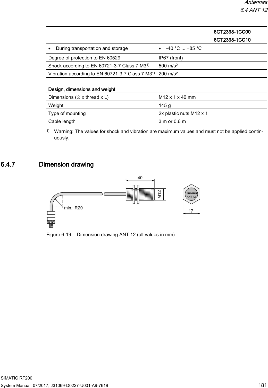
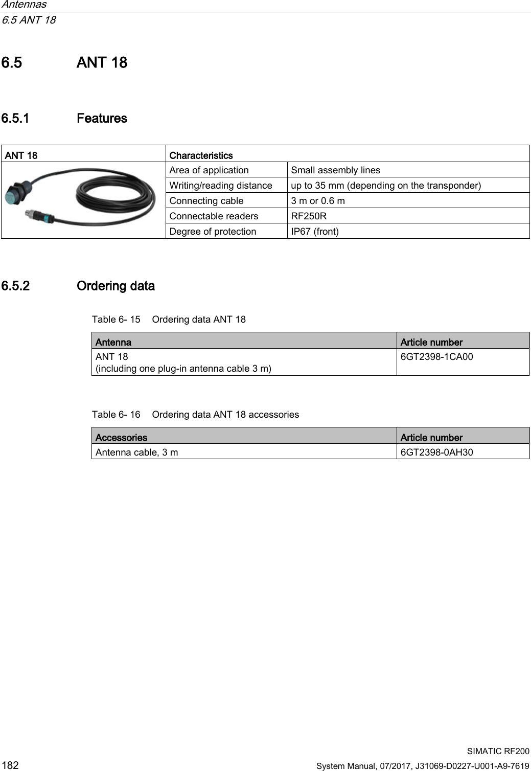
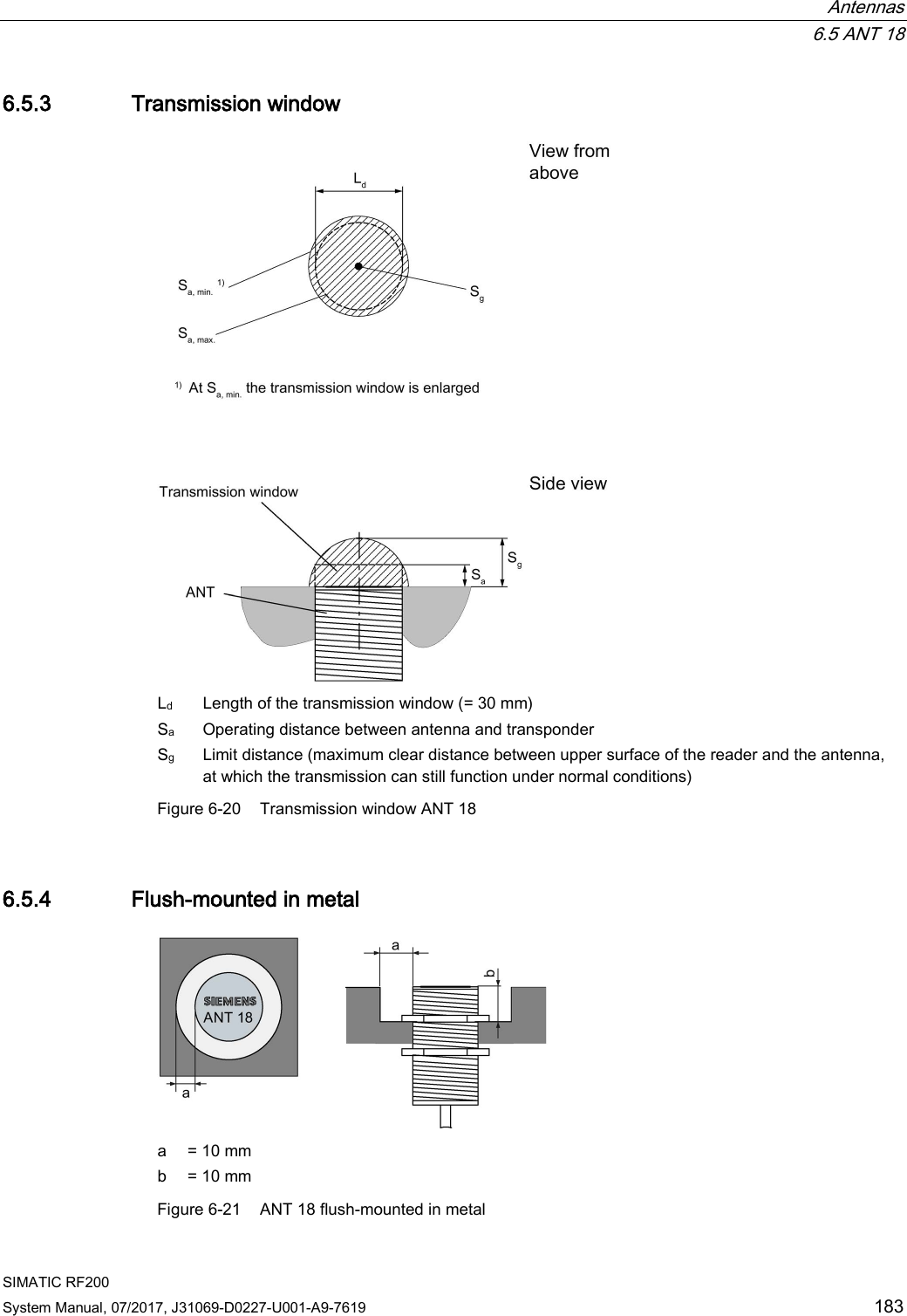
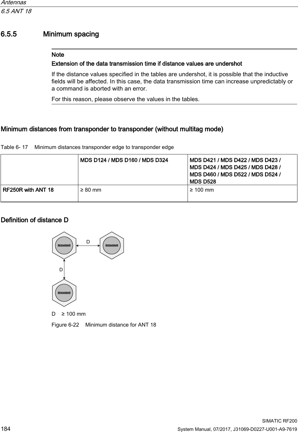
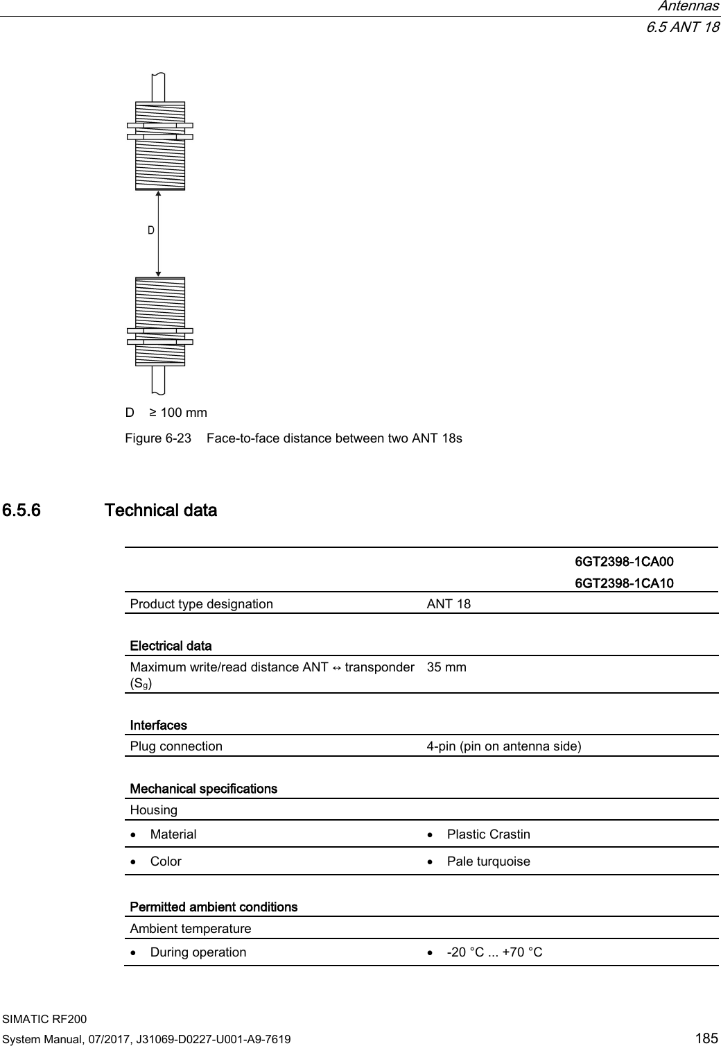
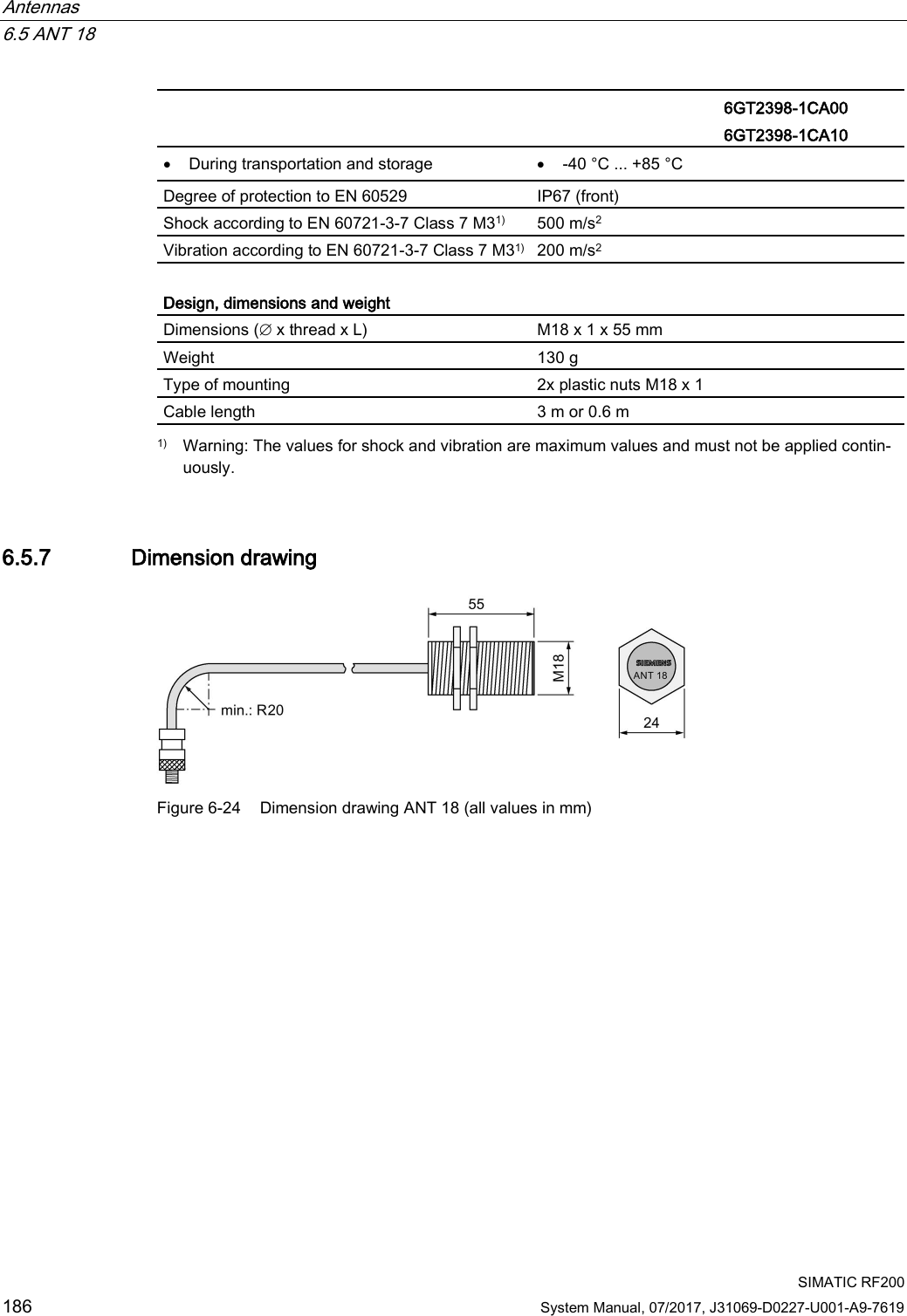
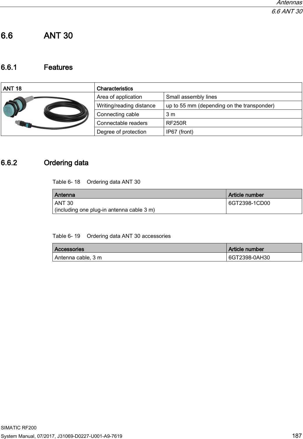
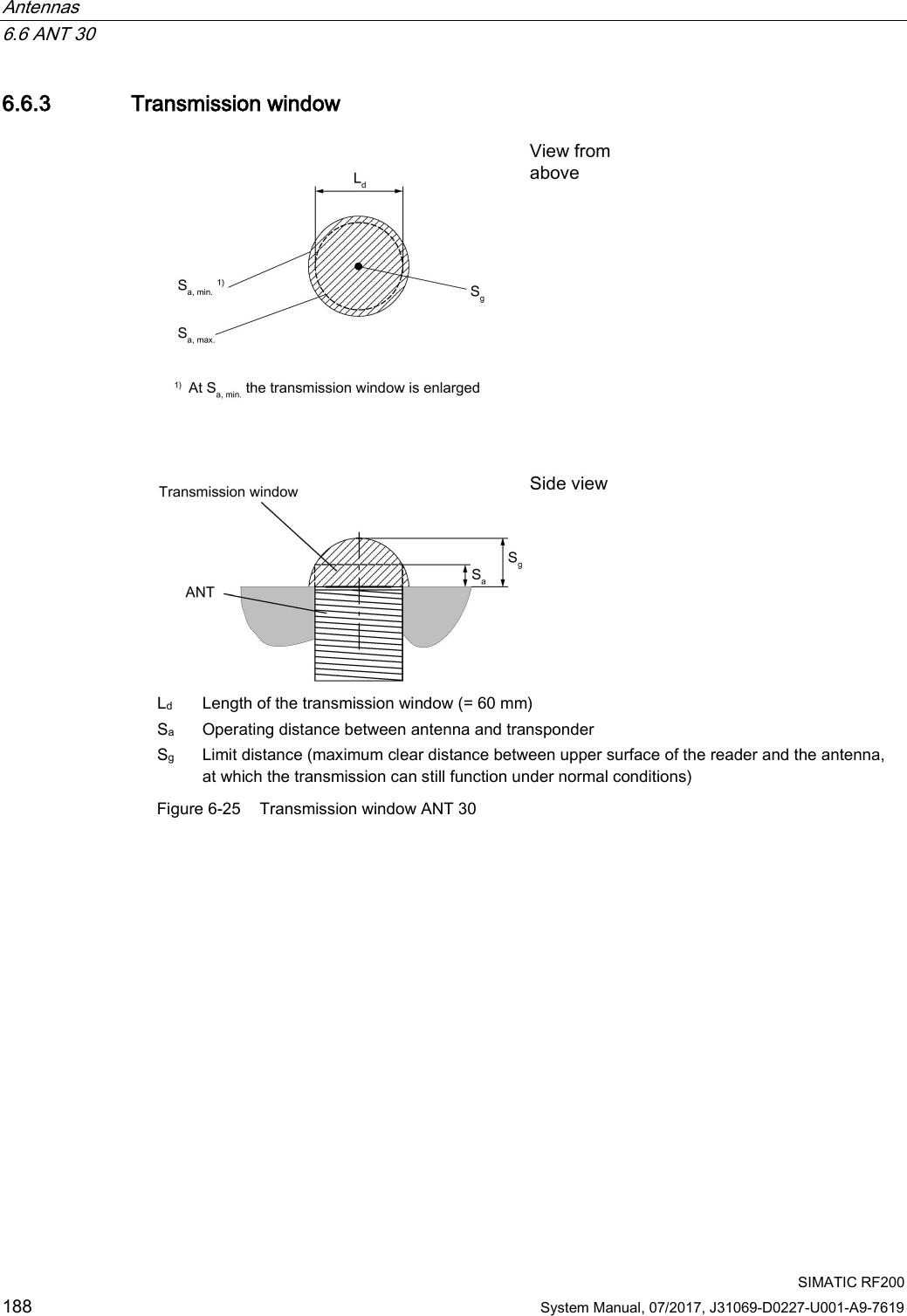
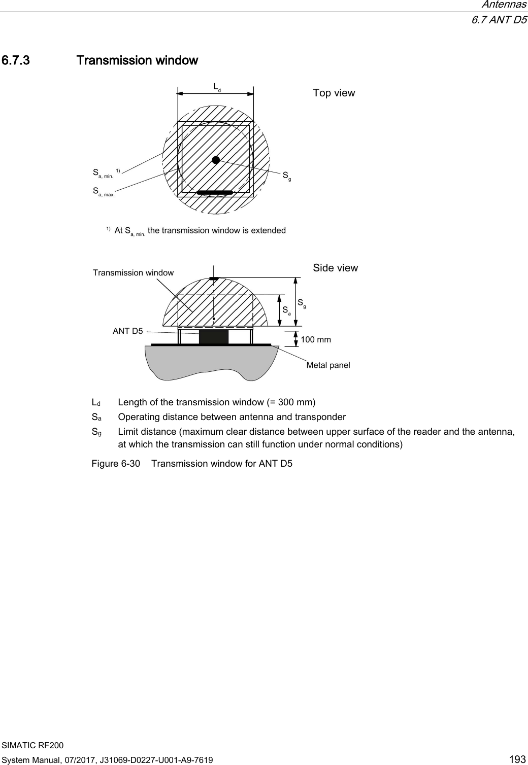
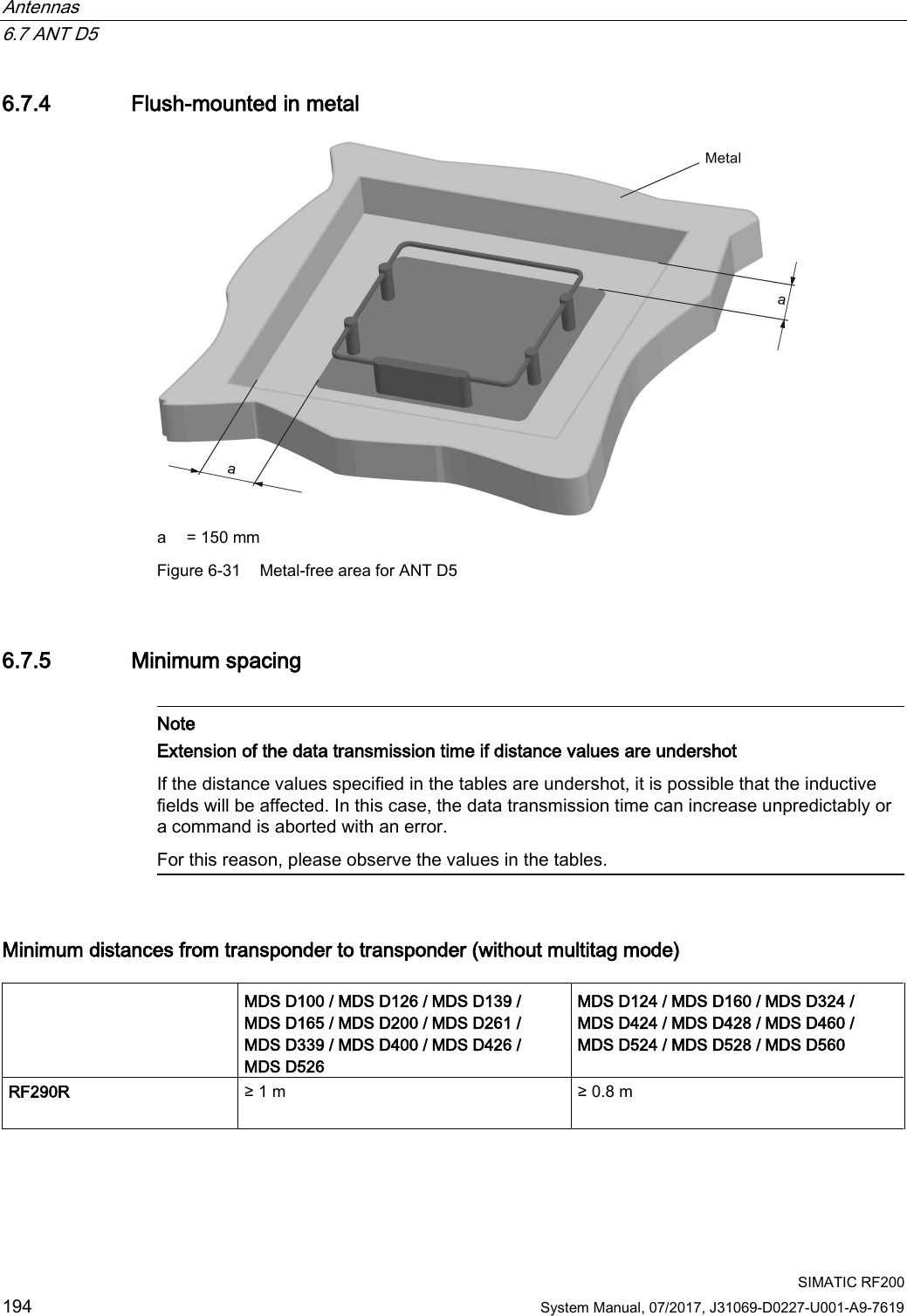
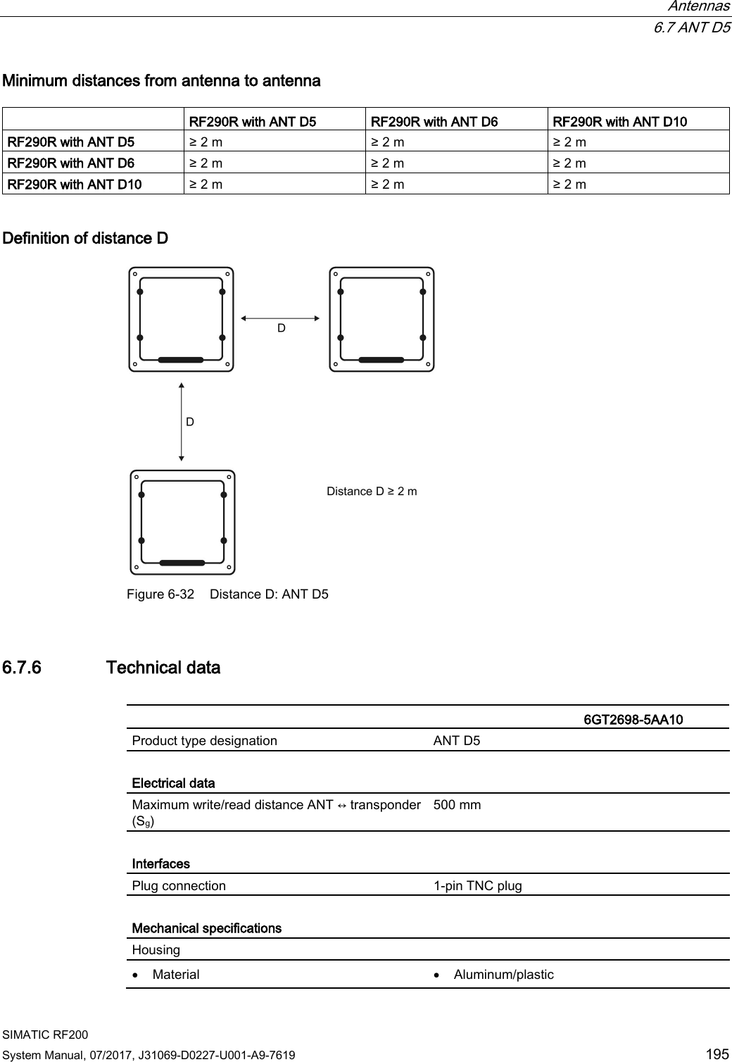
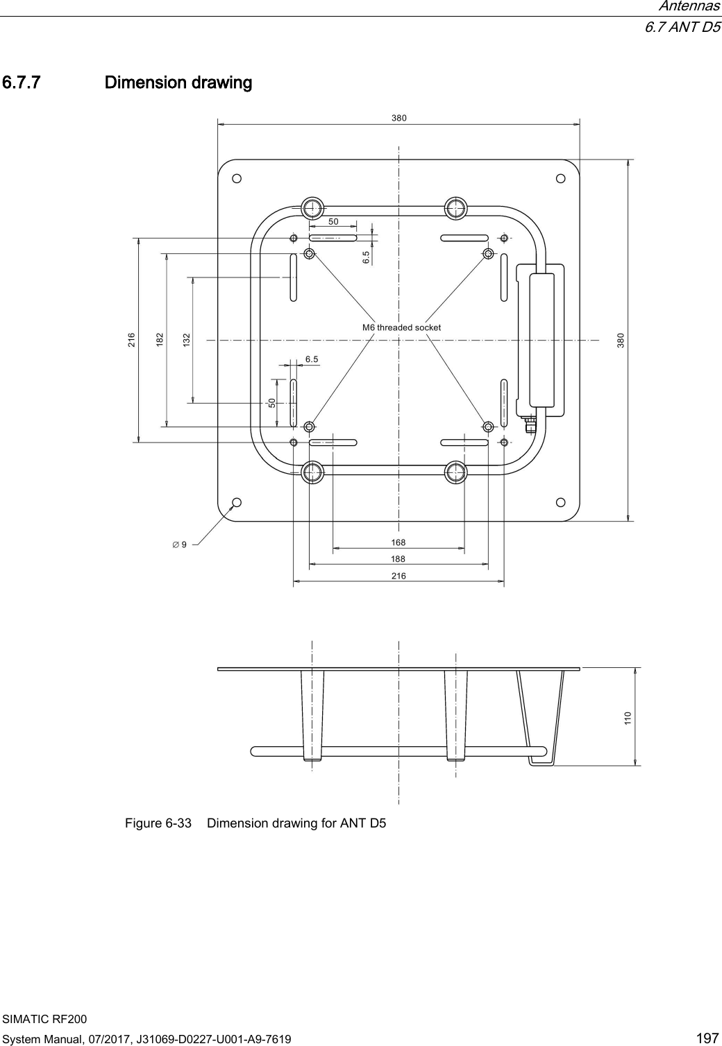
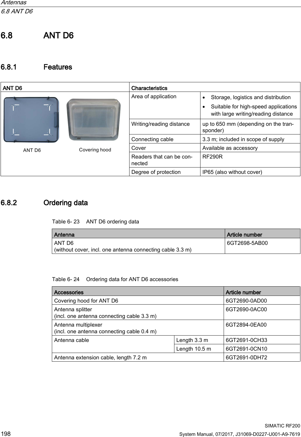
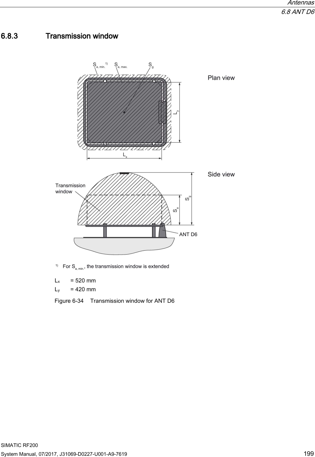
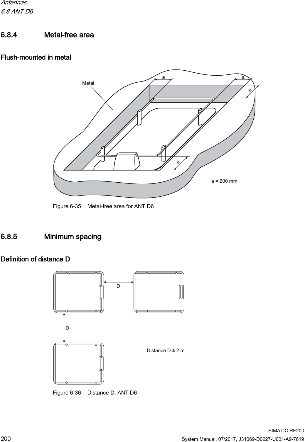
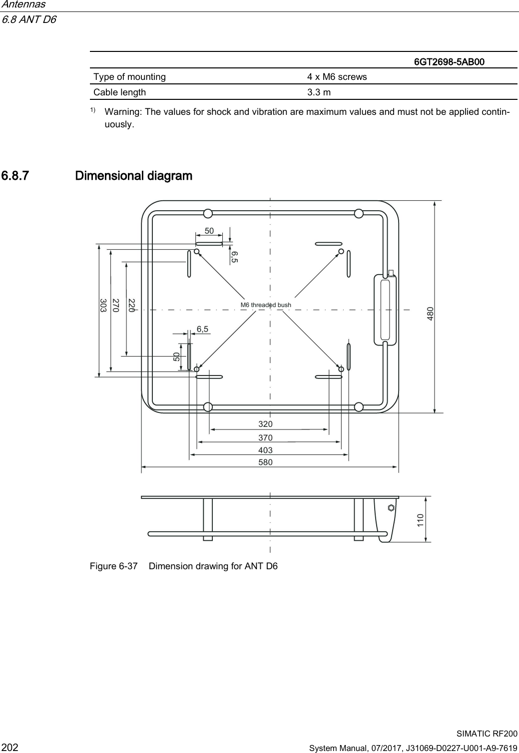
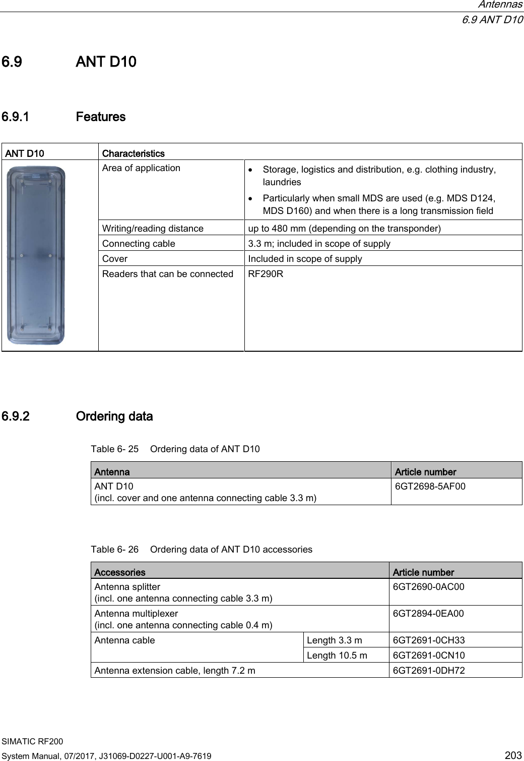
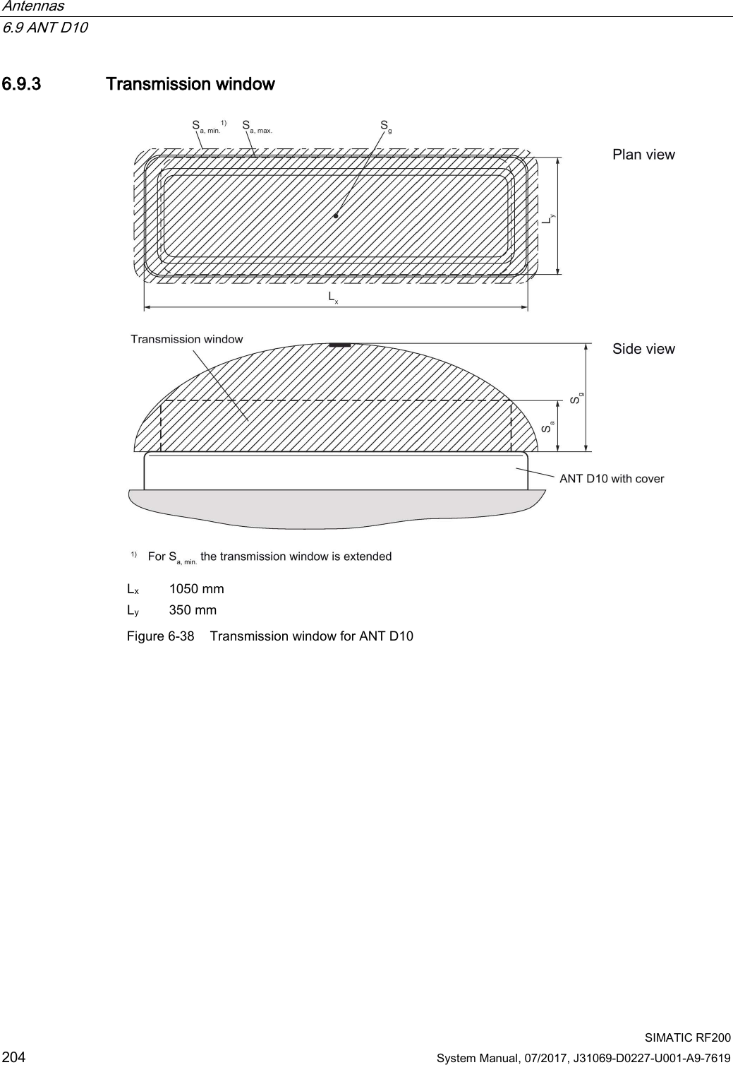
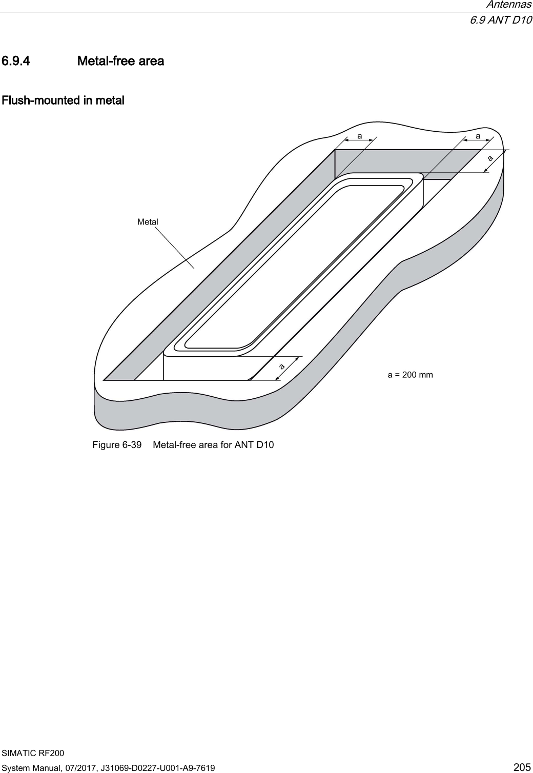
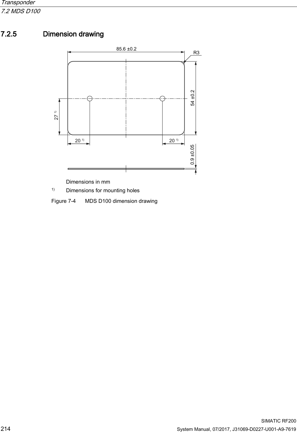
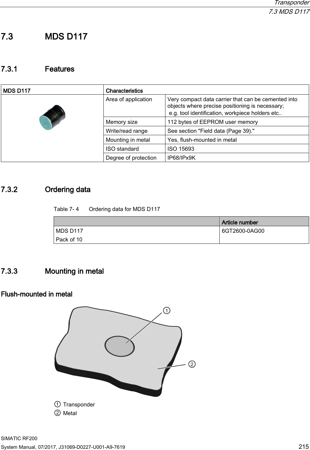
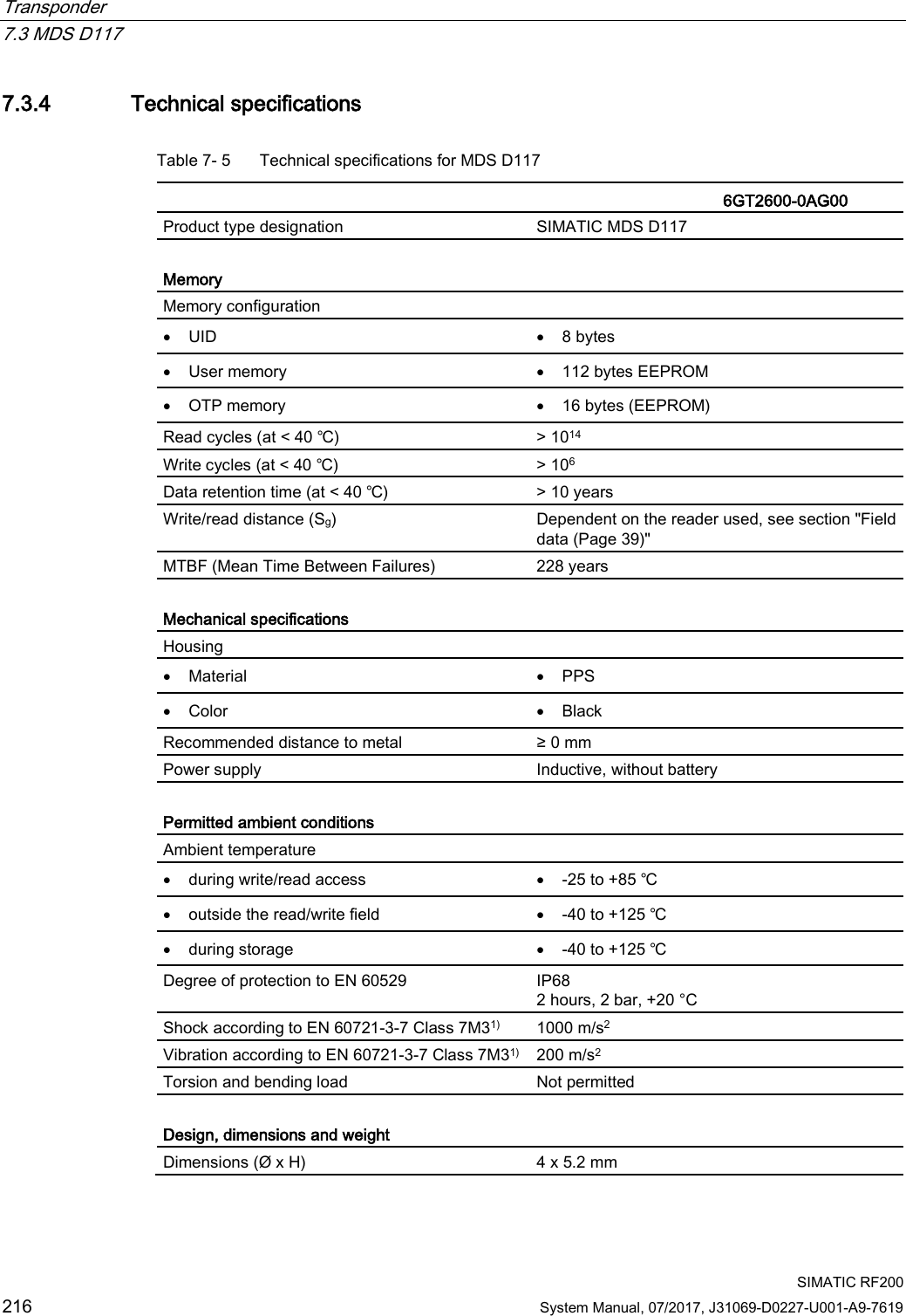
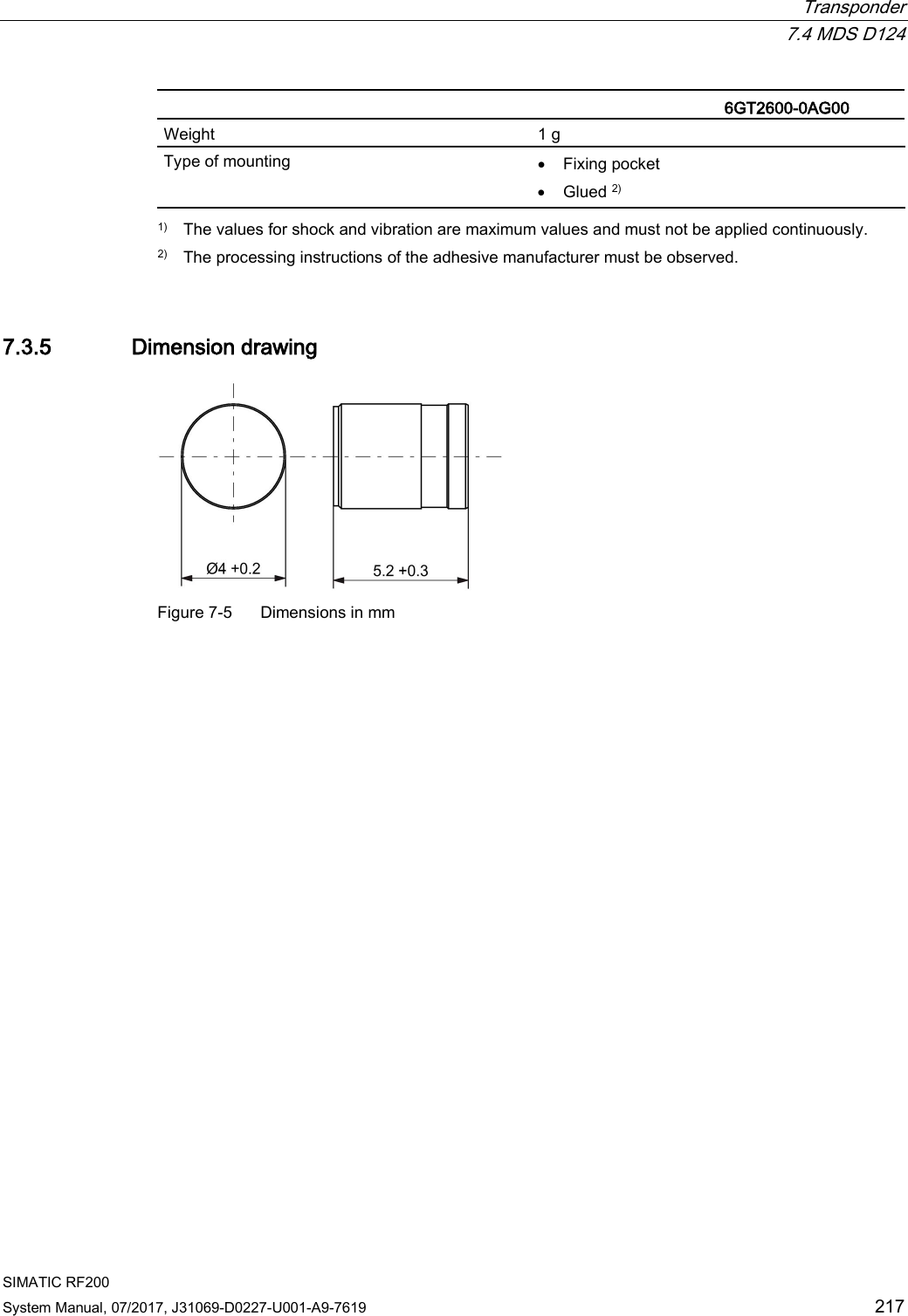
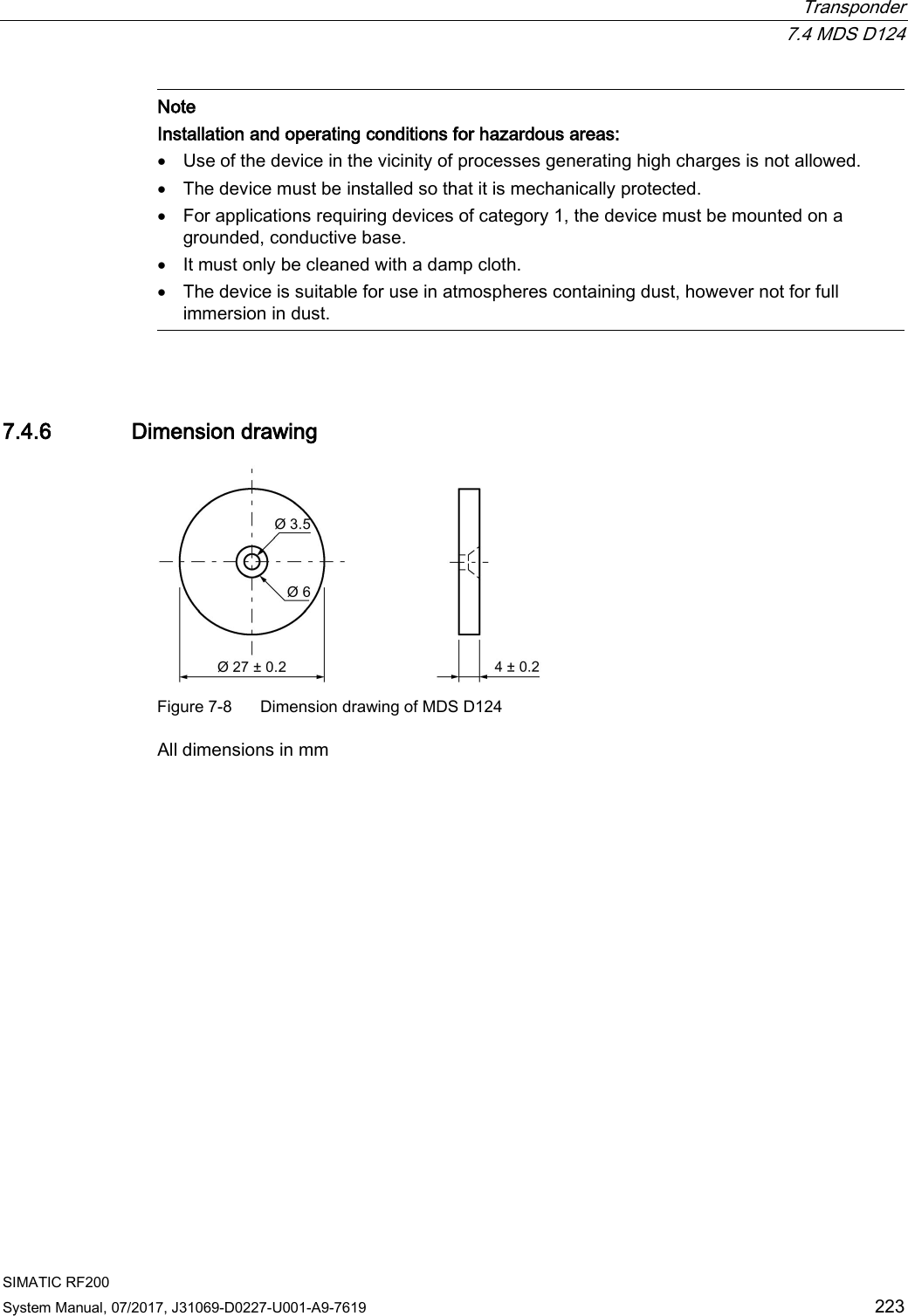
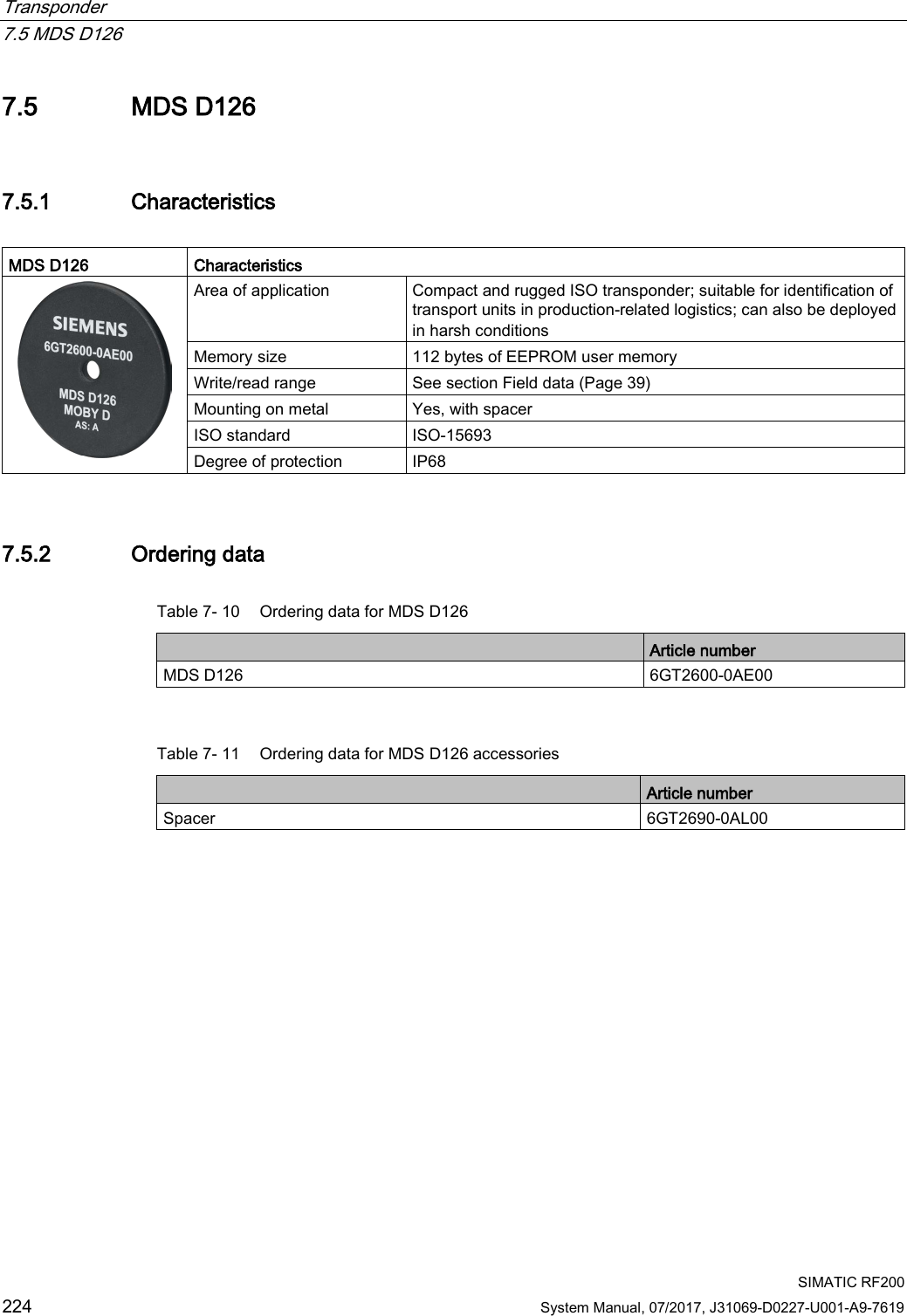
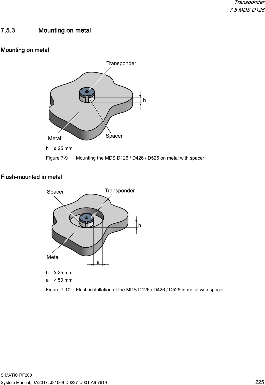
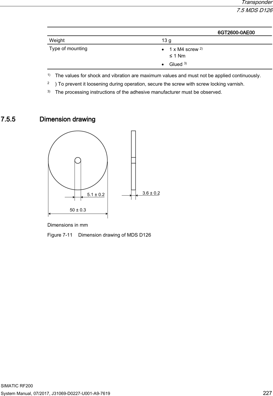
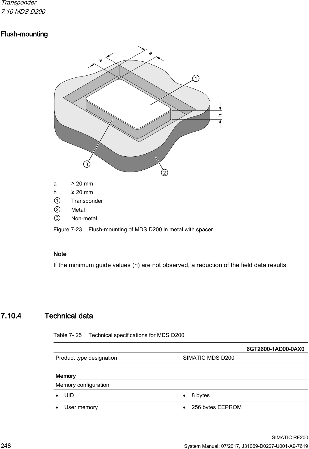
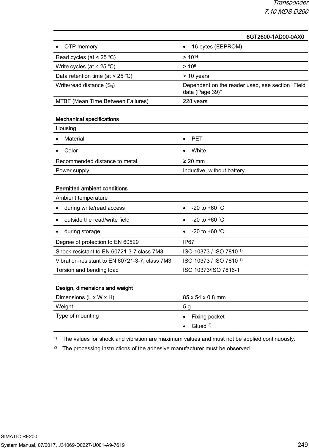
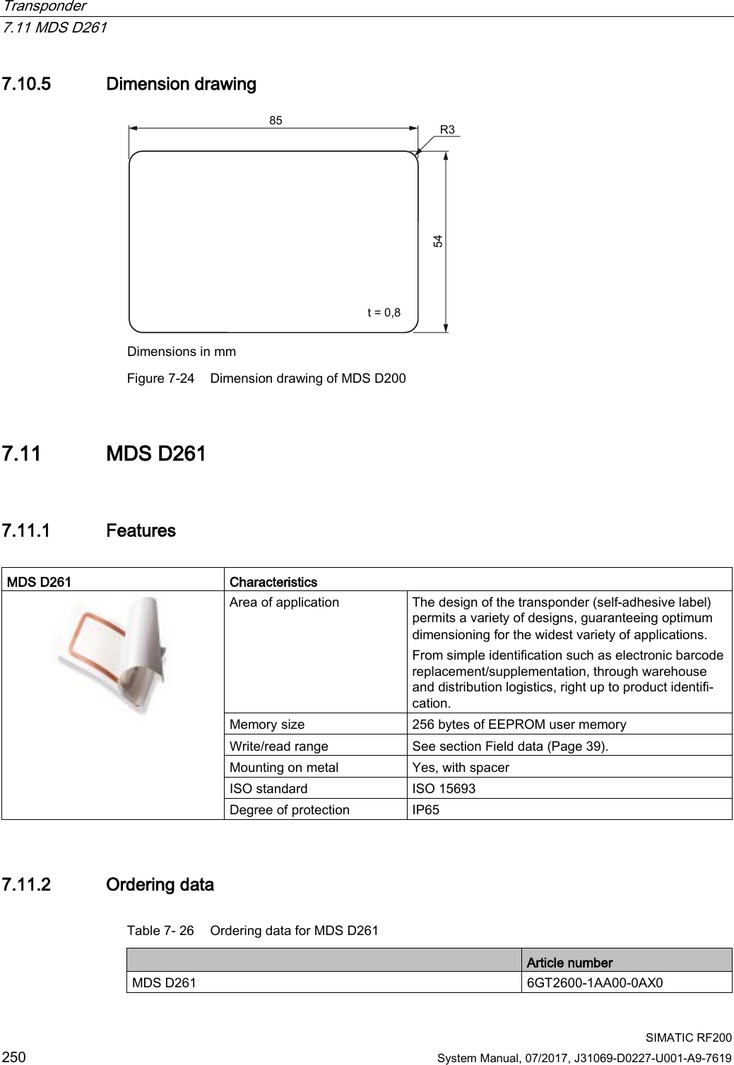
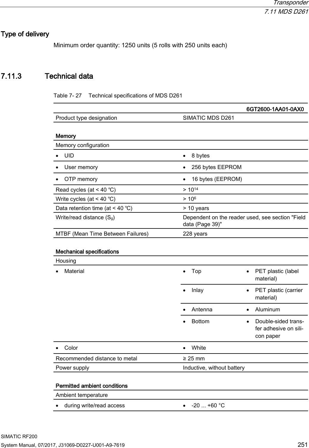
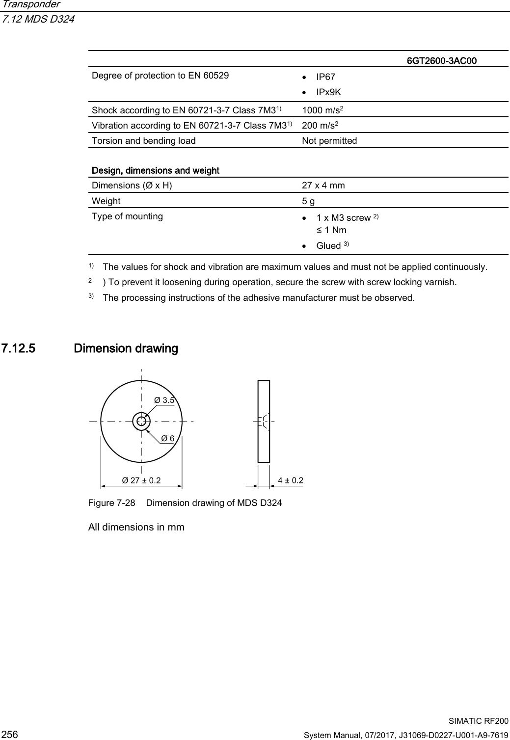
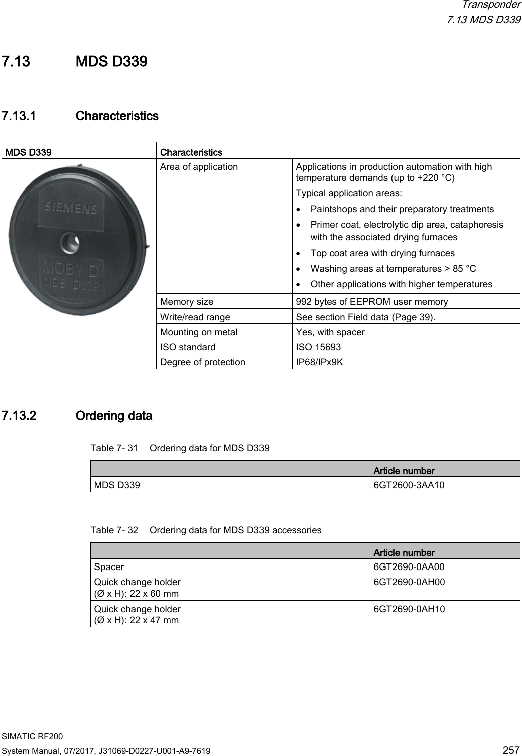
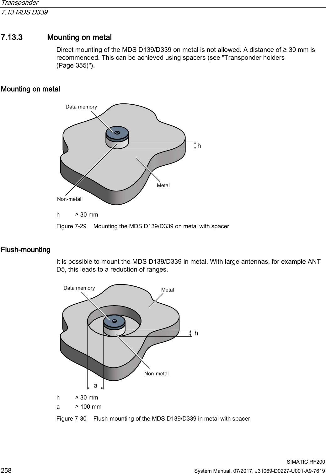
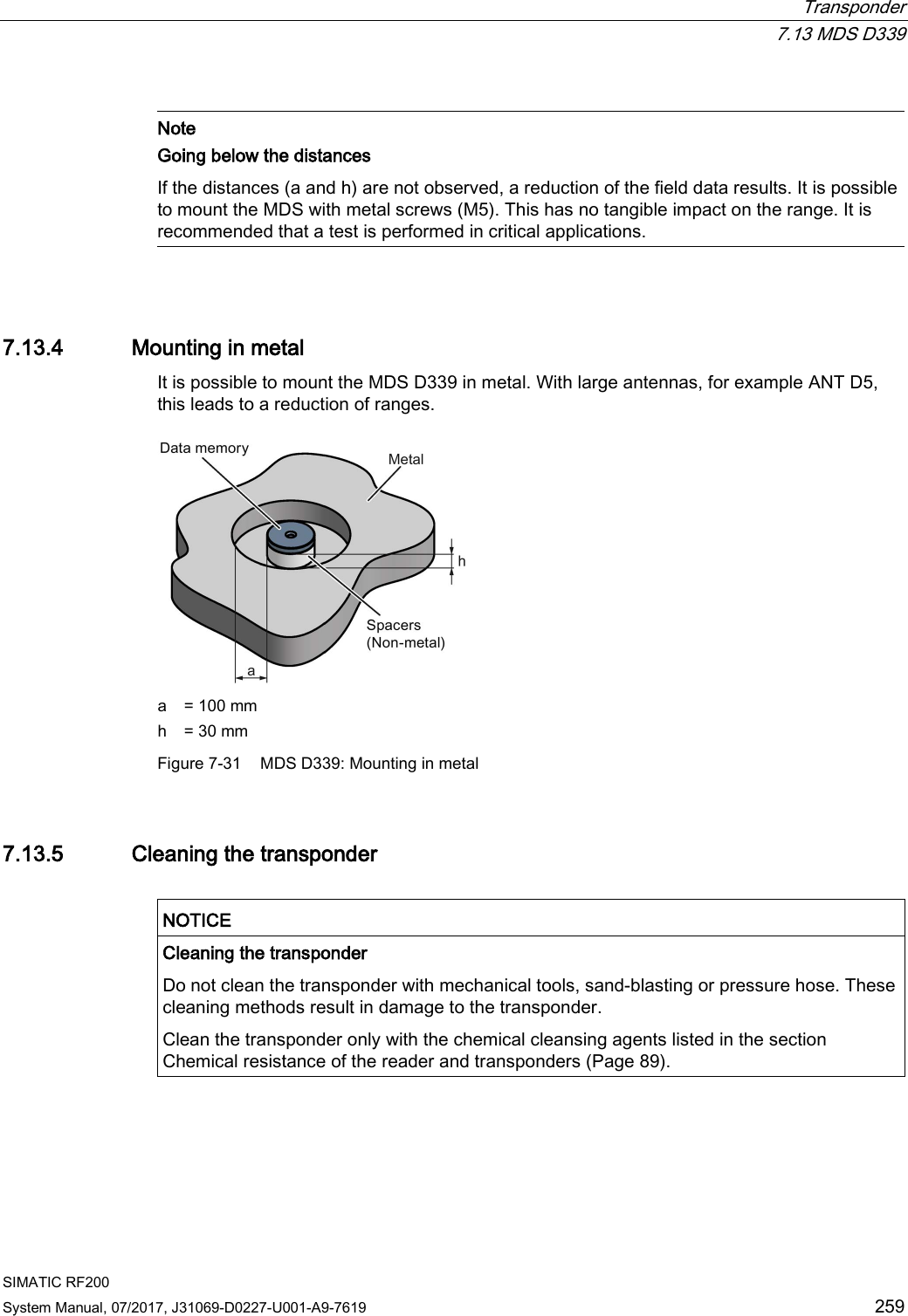
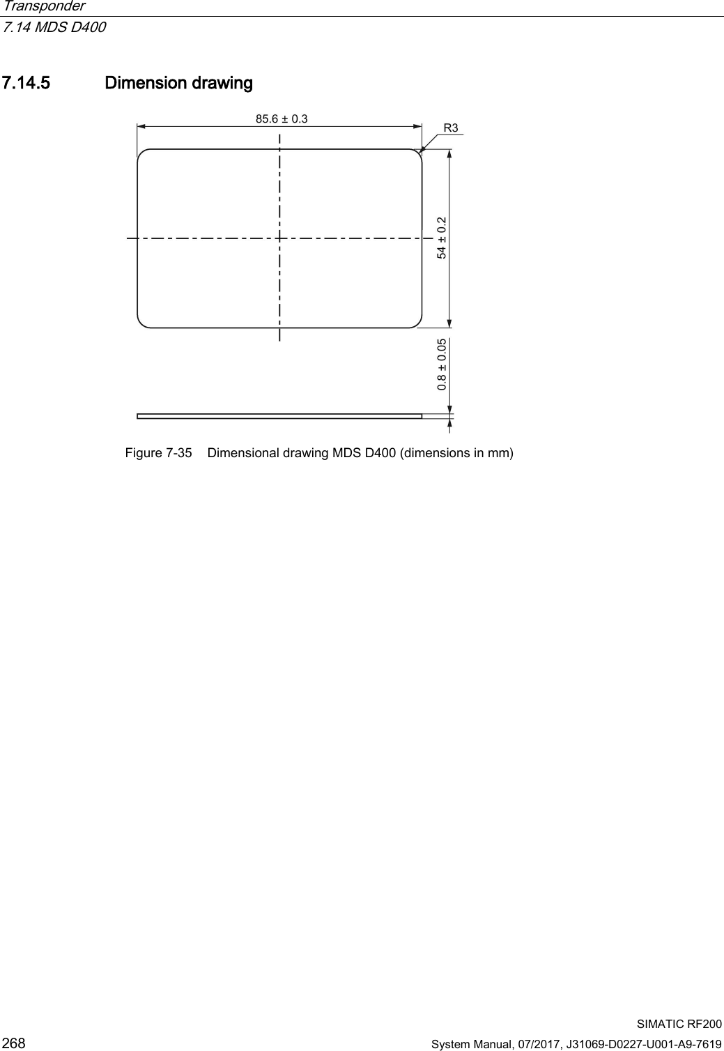
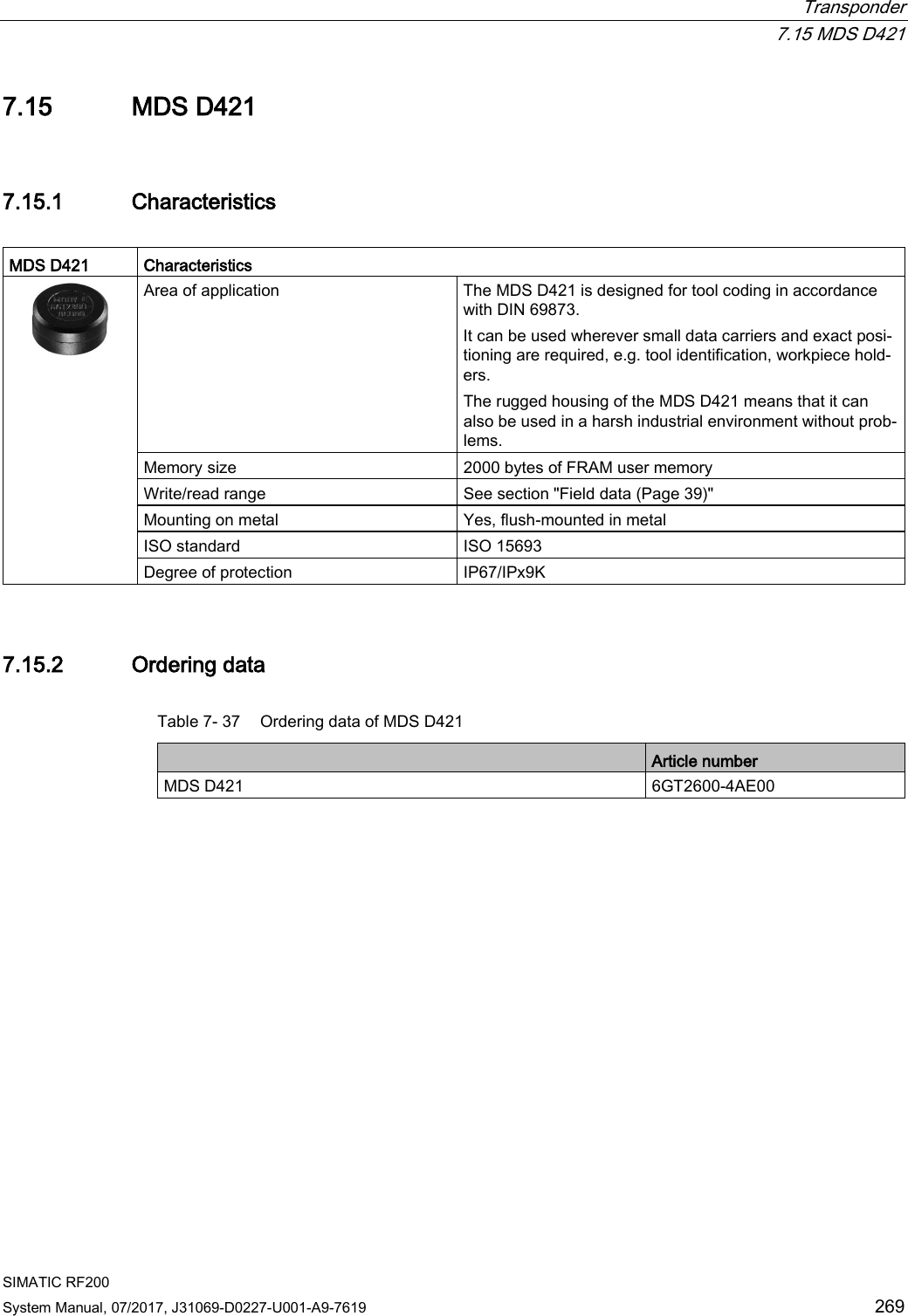
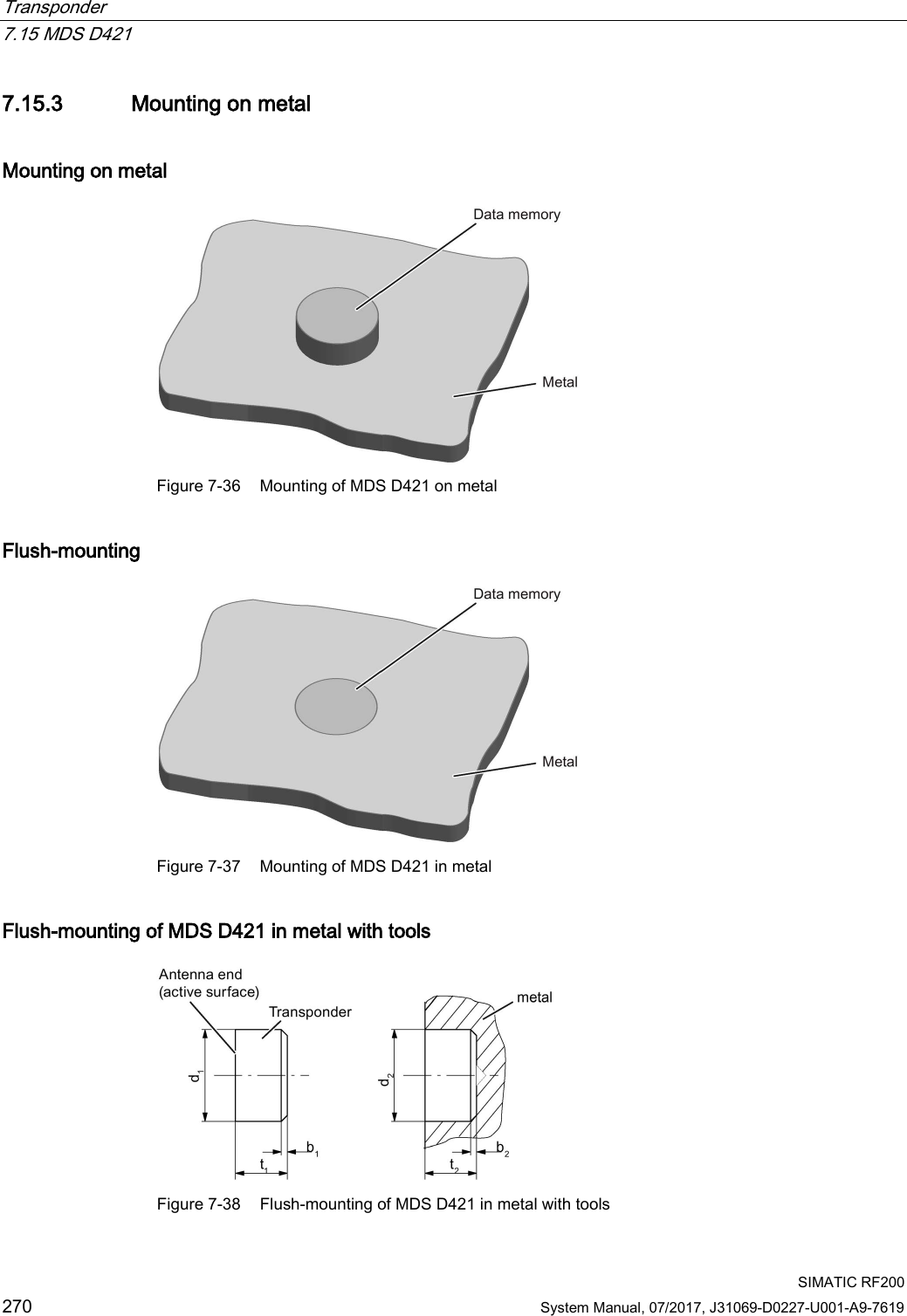
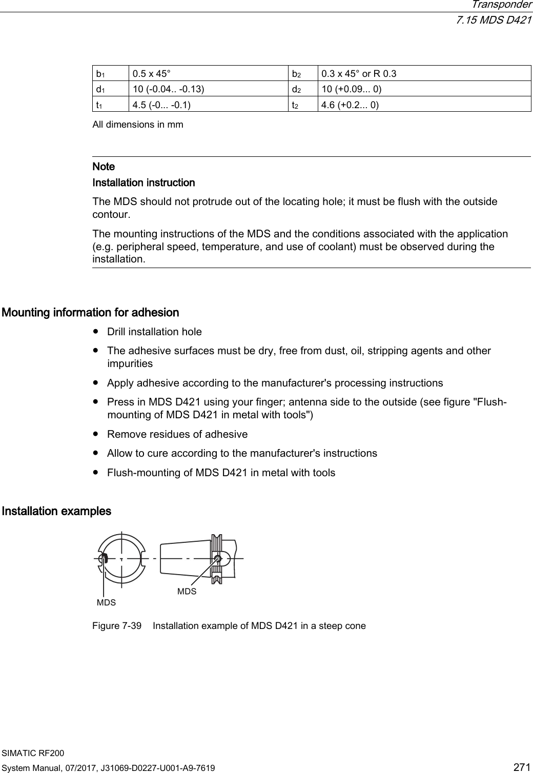
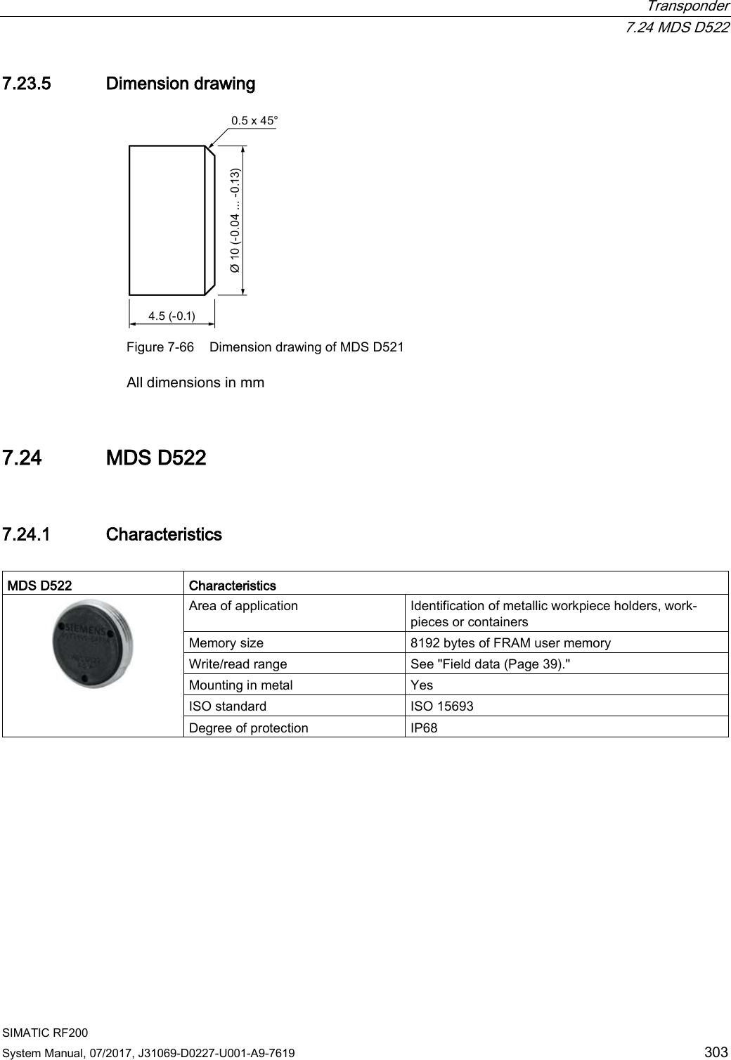
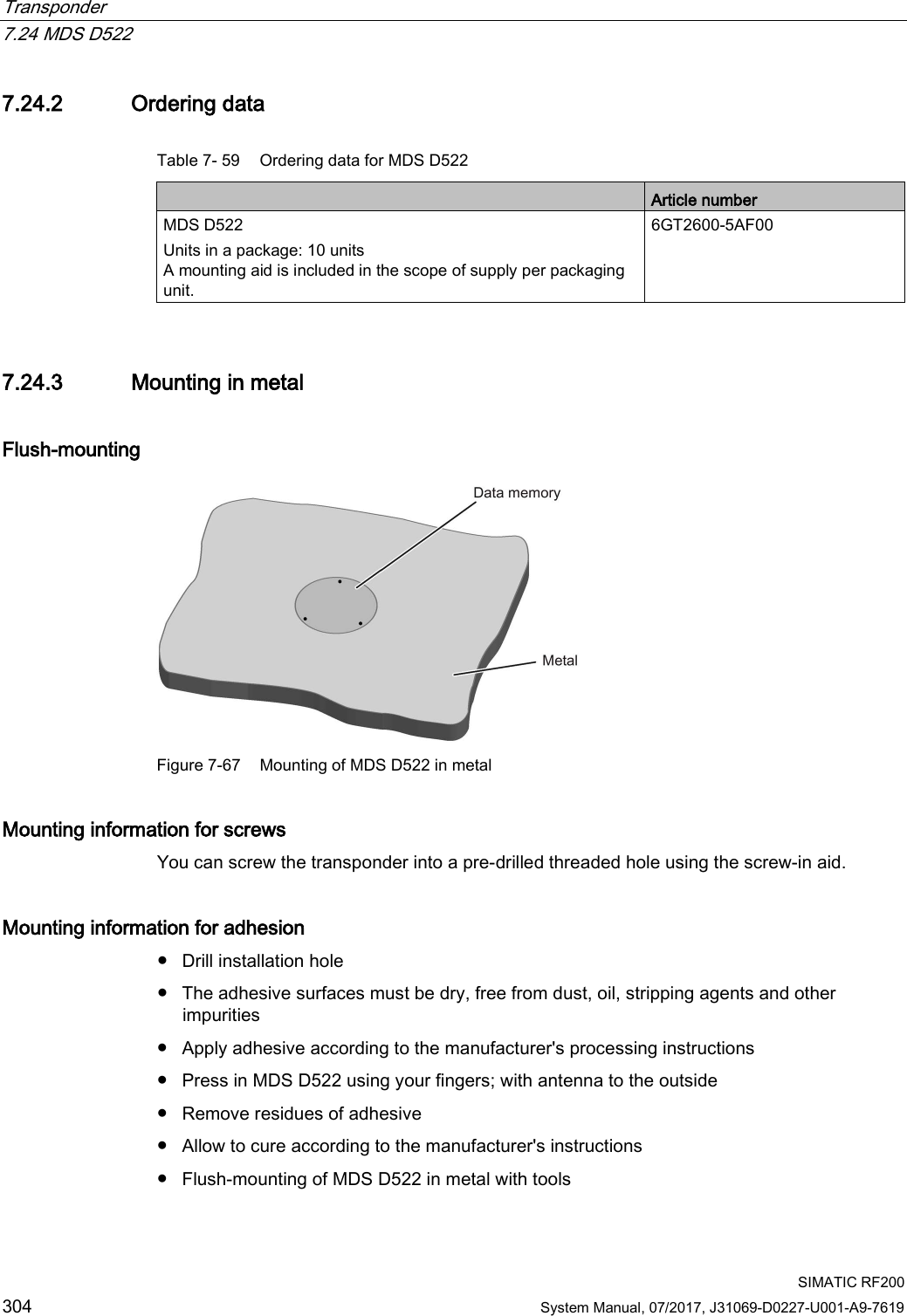
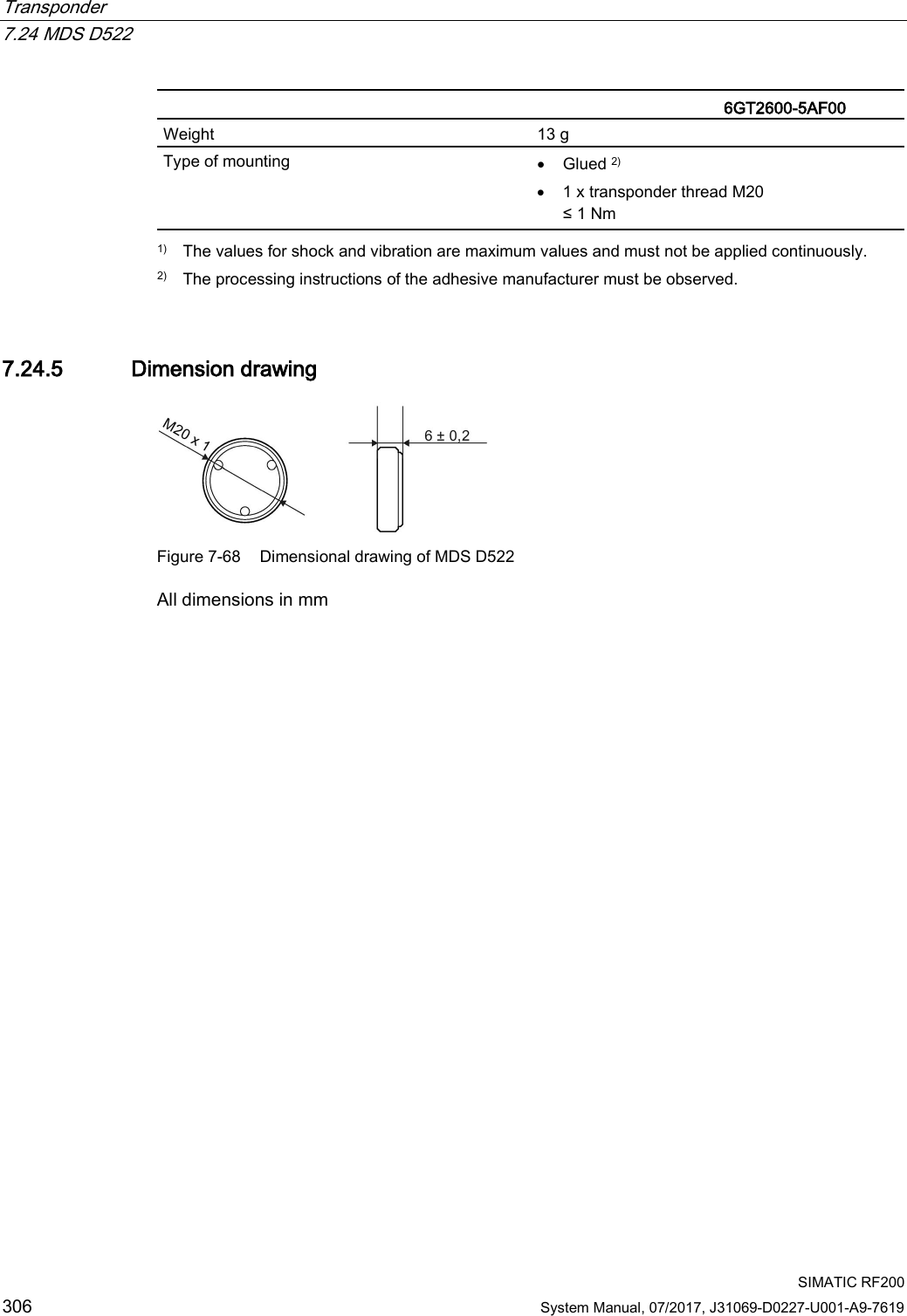
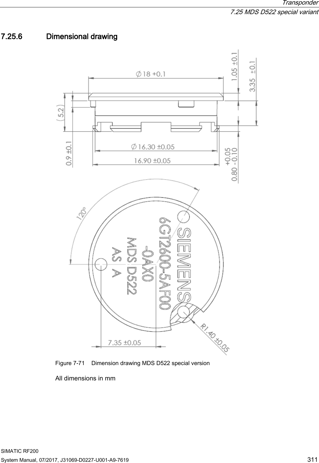
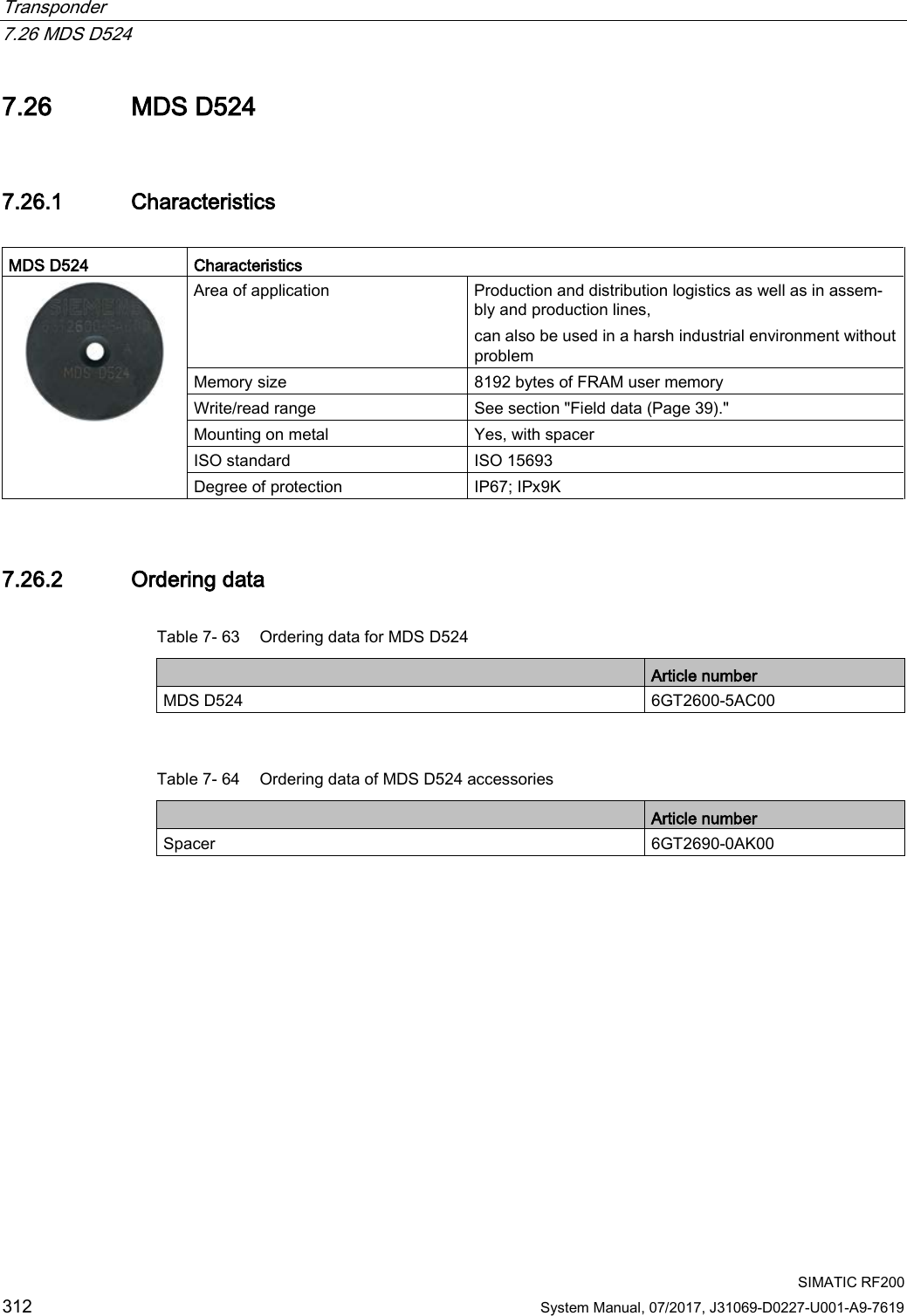
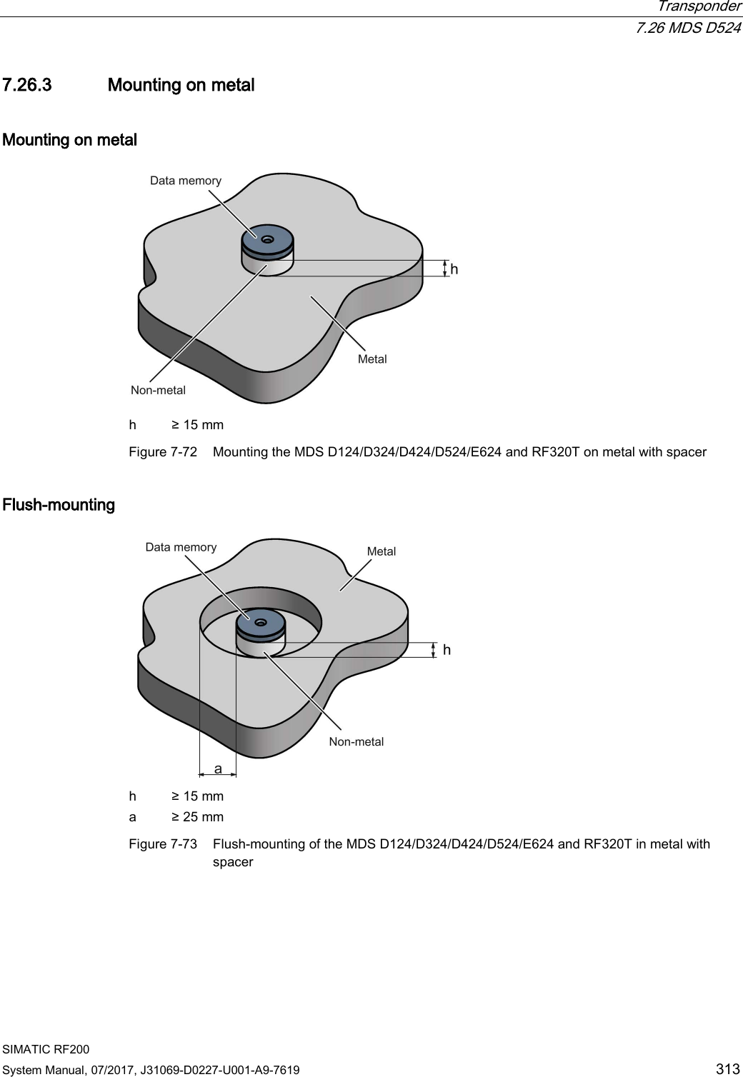
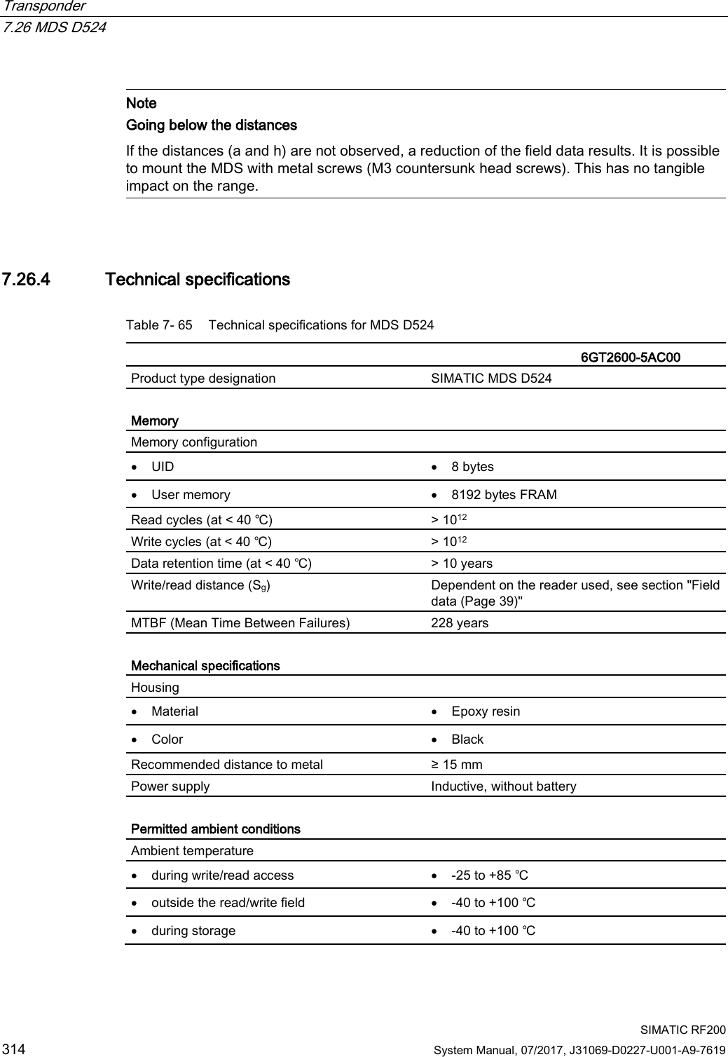
SYH_RF200_76_Part 2
3.
SYH_RF200_76_Part 3
SYH_RF200_76_Part 2
Navigation menu
Upload a User Manual
Namespaces
Wiki Guide
HTML
PDF
Info
Views
User Manual
Discussion / Help
Navigation