Shyam Telecom DB6M33SA DB6M Dual Band Repeater DB6M33-700UC+AWS User Manual
Shyam Telecom Inc. DB6M Dual Band Repeater DB6M33-700UC+AWS Users Manual
UserManual.wiki
>
Shyam Telecom
>
DB6M33SA User Manual
Users Manual
Navigation menu
Upload a User Manual
Namespaces
Wiki Guide
HTML
PDF
Info
Views
User Manual
Discussion / Help
Navigation
![. Page All Rights Reserved Shyam Telecom Limited 8/43 Next Generation Signal Enhancement CDMA Coded Division Multiple Access CMC Configuration & Monitoring Console software CMB Combiner Unit CSEL Channel Selective DCS Digital Communication System DL Downlink signal (from base station via repeater to mobile station) EGSM Extended Global System for Mobile Communication ETSI European Telecommunications Standard Institute GSM Global System for Mobile communication GUI Graphics User Interface LAC Location Area Code of the BTS site LED Light Emitting Diode LNA Low Noise Amplifier LO Local Oscillator MS Mobile Station MSC Mobile Switching Center NMS Network Management System PCN Personal Communication Network PCS Personal Communication System PSU Power Supply Unit RF Radio Frequency RMS Repeater Management System/Remote Monitoring System RSSI Received Signal Strength Indication RTC Real Time Clock SMS Short Message Service TACS Total Access Communication System TDMA Time Division Multiple Access VFD Visual Florescent Display UL (Uplink) Uplink signal direction (from mobile station via repeater to base station) 4.4. References [1] ETS 300 086 Radio Equipment and Systems Land mobile service Technical characteristics and test conditions for radio equipment with an internal or external RF connector intended primarily for analogue speech. [2] ETS 300 609-4 Digital cellular telecommunications system (phase 2): Base Station](https://usermanual.wiki/Shyam-Telecom/DB6M33SA/User-Guide-1407428-Page-8.png)
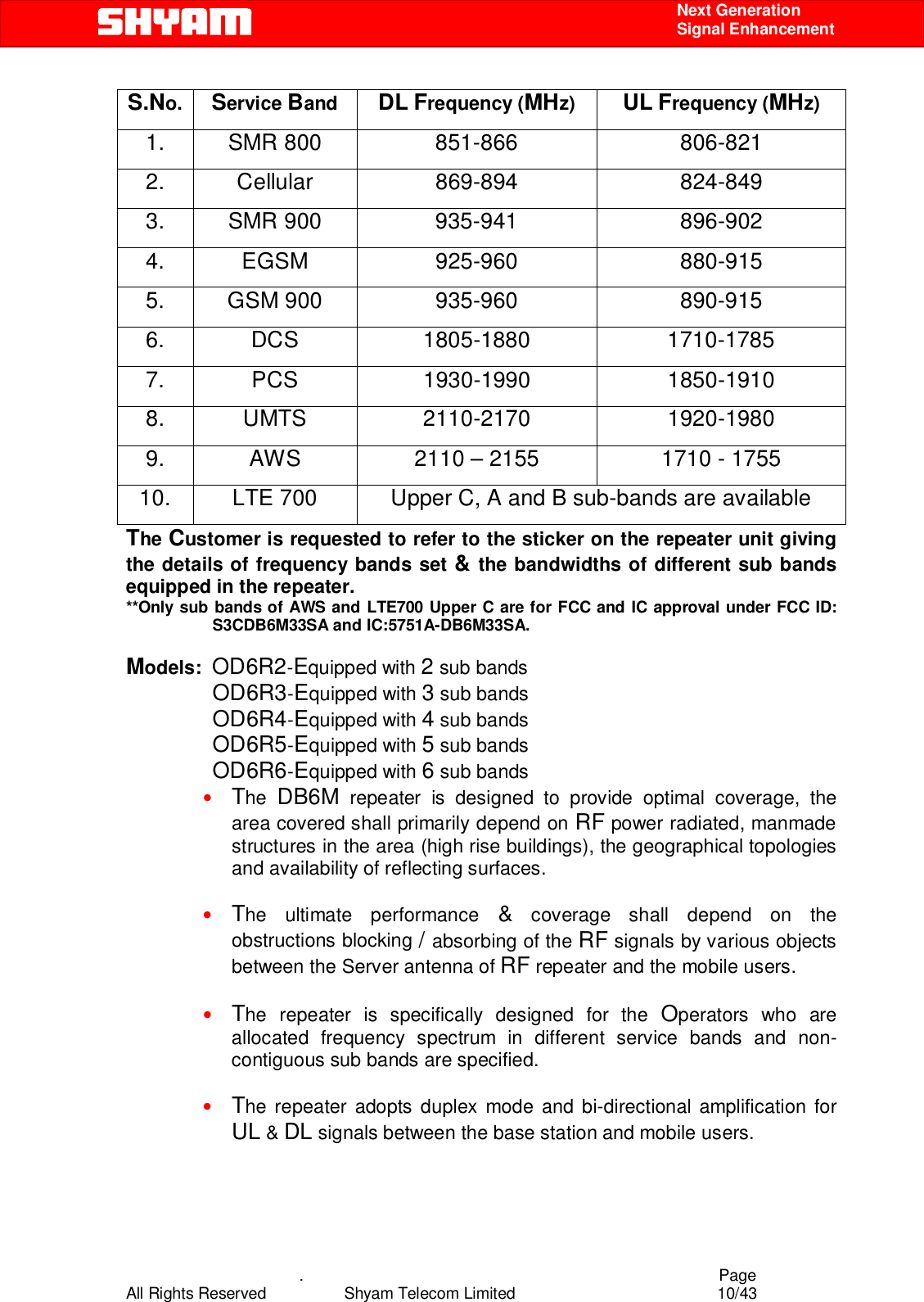
![. Page All Rights Reserved Shyam Telecom Limited 9/43 Next Generation Signal Enhancement Systems (BSS) equipment specification: Part 4: Repeaters. [3] ETS 300 342-3 Radio Equipment and Systems (RES); Electro-Magnetic Compatibility (EMC) for European Digital Cellular Telecommunications Systems. Base Station Radio and ancillary equipment and Repeaters meeting phase 2 GSM requirements. 4.5. General Mobile Communications Systems are planned as cellular systems and each cell of the base station is required to provide RF coverage over a certain geographical area as per defined RF power levels. Due to the RF propagation properties, even using high radiated RF powers or complicated antenna systems, there are zones within the coverage area where the RF signal strength from base station remains inadequate for establishing the desired connectivity to mobile users. Repeaters traditionally are deployed in the Mobile Communication Network to fill in the “Dead Zones” caused by blocking of signals by geographic topologies such as mountains, valleys, dense foliage, high rising urban landscapes and other man-made structures. The distance from the base station also adversely affects the RF signal strength. The user views repeaters as a means to extend base station coverage so as to reduce the number of base stations and thereby accelerate network availability. Repeater systems are installed after meticulous planning between BTSs and the mobile users to provide RF coverage in the shadowed regions. Repeater systems are available for different applications and ultimate choice shall depend on some of the factors mentioned below: • Area to be provided with coverage. • Indoor/outdoor coverage. • Availability of BTSs in the vicinity. • Antenna isolation to be achieved. 5. Functional Description of DB6M Dual Band Repeater 5.1. General Description The DB6M dual band modular Repeater System is designed to provide outdoor coverage and can handle signals in up to six sub bands maximum with 3+3 configuration or as per requirement in two of the service bands, used around the World by various service operators. It provides highly selective amplification in the pre-set frequency bands. The details of operating service frequency bands are given below: SNo Service Band DL Frequency (MHz) UL Frequency (MHz)](https://usermanual.wiki/Shyam-Telecom/DB6M33SA/User-Guide-1407428-Page-9.png)
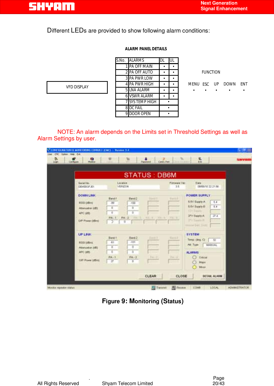
![. Page All Rights Reserved Shyam Telecom Limited 19/43 Next Generation Signal Enhancement 8 UL Manual PA OFF (Band 1 & Band 2) When PA Manual OFF is detected in any or the two or both bands in UL path, alarm is generated. 9 System Temperature High When system Temperature exceeds the upper limit, alarm is generated. 10 Synthesizer failure (For equipped sub bands in DL & UL) When the Synthesizer in any of the equipped sub bands fails, relevant alarm is displayed. 11 VSWR (DL) It indicates that the mismatch has occurred in DL due to which VSWR value has exceeded 1.5:1. 12 VSWR (UL) It indicates that the mismatch has occurred in UL due to which VSWR value has exceeded 1.5:1. Monitoring interval is 3 seconds i.e. after every 3 seconds data on the monitoring window is refreshed. Red indication is for Alarm present. Green indication is for No Alarm. VFD (Visual Florescent Display): This display facilitates configuration & monitoring of the system without connecting the PC/Laptop at the USB port. Press buttons are provided on the VFD strip with following markings with LEDs to display alarm conditions if any: • Menu [Status and Configuration captions are visible; either of the two can be selected at a time]. • UP [It facilitates shifting of arrow (marker) up in Menu to select the desired function]. • Down [It facilitates shifting of arrow (marker) down in Menu to select the desired function]. • ENT [It enables to view different parameters/conditions prevailing in the system depending on function selected through MENU viz. configuration or status by pressing]. • ESC [It facilitates restoring the original state].](https://usermanual.wiki/Shyam-Telecom/DB6M33SA/User-Guide-1407428-Page-19.png)