Shyam Telecom BTSLINK-208 BTS Link-208 Repeater User Manual 1
Shyam Telecom Inc. BTS Link-208 Repeater 1
UserManual.wiki
>
Shyam Telecom
>
BTSLINK-208 User Manual
>
User Manual 1
Contents
1.
User Manual 1
2.
User Manual 2
User Manual 1
Navigation menu
Upload a User Manual
Namespaces
Wiki Guide
HTML
PDF
Info
Views
User Manual
Discussion / Help
Navigation
![All Rights Reserved Shyam Telecom Limited Page 6 / 40 Next Generation Signal Enhancement 4.2. Scope This document is the product description of the Shyam BTS Link-208 Repeater. 4.3. Definitions AGC Automatic Gain Control ALC Automatic Level Control APC Automatic Power Control BTS Base Transceiver Station CDMA Coded Division Multiple Access CMC Configuration & Monitoring Console software DBROU Dual Band Remote Optical Unit DCS Digital Communication System DL Downlink signal (from base station via repeater to mobile station) EGSM Extended Global System for Mobile Communication ETSI European Telecommunications Standard Institute FDF Fiber Distribution Frame GSM Global System for Mobile communication IMD Inter Modulation Distortion LAC Location Area Code of the BTS site LED Light Emitting Diode LNA Low Noise Amplifier LO Local Oscillator MOU Master Optical Unit MS Mobile Station NMS Network Management System PCN Personal Communication Network PCS Personal Communication System PSU Power Supply Unit RF Radio Frequency RMS Remote Management System ROU Remote Optical Unit RSSI Received Signal Strength Indication UL (Uplink) Uplink signal direction (from mobile station via repeater to base station) UMTS Universal Mobile Telecommunication System 4.4. References [1] ETS 300 086. Radio Equipment and Systems Land mobile service Technical characteristics and test conditions for radio equipment with an internal or external RF connector intended primarily for analogue speech.](https://usermanual.wiki/Shyam-Telecom/BTSLINK-208.User-Manual-1/User-Guide-964140-Page-6.png)
![All Rights Reserved Shyam Telecom Limited Page 7 / 40 Next Generation Signal Enhancement [2]ETS300609-4. Digital cellular telecommunications system (phase 2): Base Station Systems (BSS) equipment specification: Part 4: Repeaters. [3] ETS 300 342-3 Radio Equipment and Systems (RES); Electro-Magnetic Compatibility (EMC) for European Digital Cellular Telecommunications systems. Base Station Radio and ancillary equipment and Repeaters meeting phase 2 GSM requirements. 4.5. General Mobile Communications Systems are planned as cellular systems and each cell of the base station is required to provide RF coverage over a certain geographical area as per defined RF power levels. Due to the RF propagation properties, even using high radiated RF powers or complicated antenna systems, there are zones within the coverage area where the RF signal strength from base station remains inadequate for establishing the desired connectivity to mobile users. Repeaters traditionally are deployed in the Mobile Communication Network to fill in the “Dead Zones” caused by blocking of signals by geographic topologies such as mountains, valleys, dense foliage, high rise urban landscapes, and other man-made structures. The distance from the base station also adversely affects the RF signal strength. The user views repeaters as a means to extend base station coverage so as to reduce the number of base stations and thereby accelerate network availability. Repeater systems are installed after meticulous planning between BTSs and the mobile users to provide RF coverage in the shadowed regions. Repeater systems are available for different applications and ultimate choice shall depend on some of the factors mentioned below: • Area to be provided with coverage. • Indoor/outdoor coverage. • Availability of BTSs in the vicinity. 5. Functional Description of BTS Link-208 Repeater 5.1. General Description The BTS Link-208 Repeater System is designed to provide indoor coverage and can handle signals in two service bands viz. Cellular & PCS, used by various service operators. It provides highly selective amplification in the pre-set bands. The details of operating frequencies are:](https://usermanual.wiki/Shyam-Telecom/BTSLINK-208.User-Manual-1/User-Guide-964140-Page-7.png)
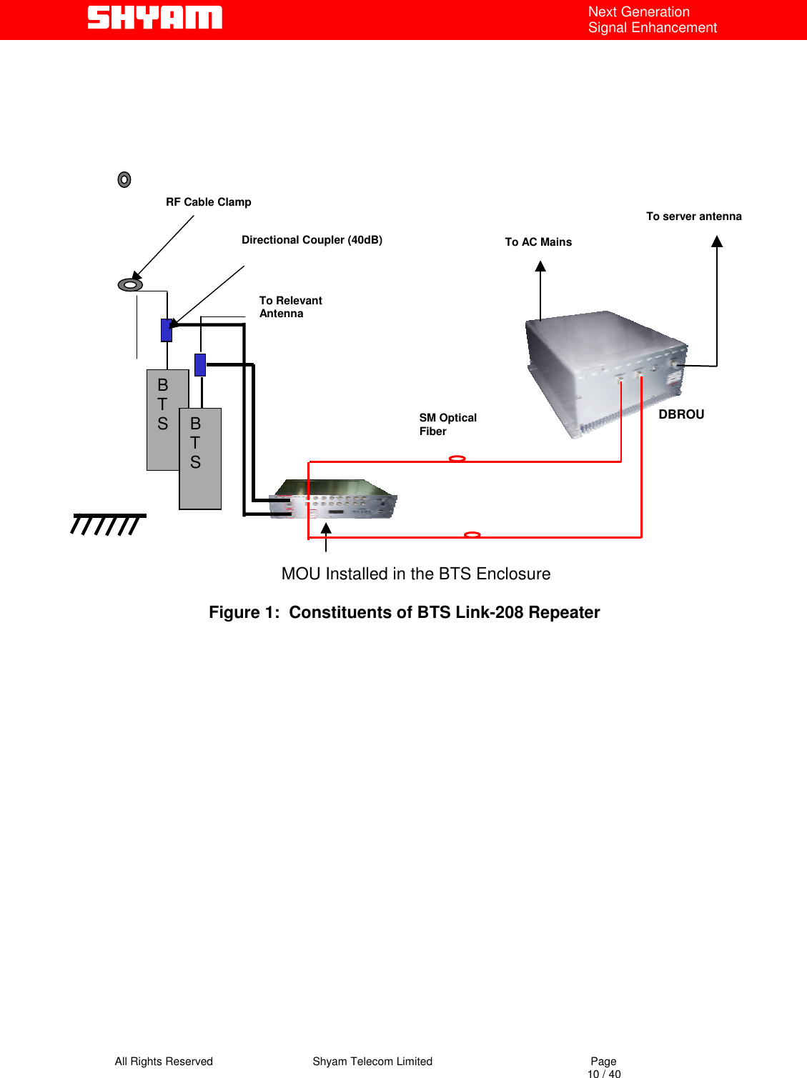
![All Rights Reserved Shyam Telecom Limited Page 8 / 40 Next Generation Signal Enhancement Cellular 869 MHz to 894 MHz (DL) 824 MHz to 849 MHz (UL) PCS 1930 MHz to 1990 MHz (DL) 1850 MHz to1910 MHz (UL) • The BTS Link-208 repeater system is a dual band Distributed Antenna System (DAS) for point to point & point to multi-point coverage. • It is comprised of a Master Optical Unit (MOU) and Dual Band Remote Optical Units (DBROUs), maximum 8, installed at different sites. MOU & DBROUs are connected through a pair of optical fibers. • DBROUs with appropriate housings for indoor application can be installed at the pre-planned sites. • Master Optical Unit (MOU) is installed at indoor location close to BTSs from where the signals are to be received and also OFC terminations destined for DBROUs at different sites are available. • The repeater is deployed in the network where RF coverage is required for large clusters of mobile users at different sites. • The repeater can be equipped with a RMS (Optional) for speedy maintenance & monitoring. • The antenna isolation problem is of little consequence since the signals between MOU and DBROUs are propagated as optical signals, which are insensitive to any electrical interference/disturbances. The system is comprised of two units: I) Master Optical Unit (MOU): The MOU is installed at a suitable indoor location close to the BTS. It receives/transmits RF signals in dual band from the BTSs through BTS couplers and optical signals from different DBROUs. It consists of modules/units: • Duplexers [Band 1 & Band 2] • Optical Transmitter Unit (OTX) • Optical Splitter (1:4) • Optical Receiver Unit (ORX) • Power Supply Unit • Gain modules • Supervisory and ASK modem • A metallic housing (Indoor application) accommodates all the above units/modules. Arrangement is made for dissipation of heat generated in the unit and the unit is not waterproof.](https://usermanual.wiki/Shyam-Telecom/BTSLINK-208.User-Manual-1/User-Guide-964140-Page-8.png)
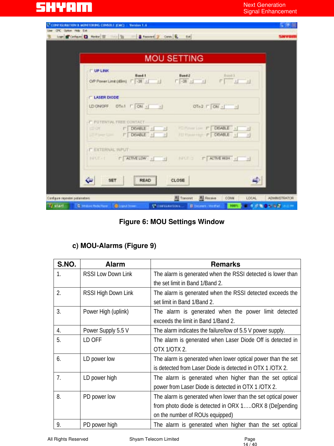
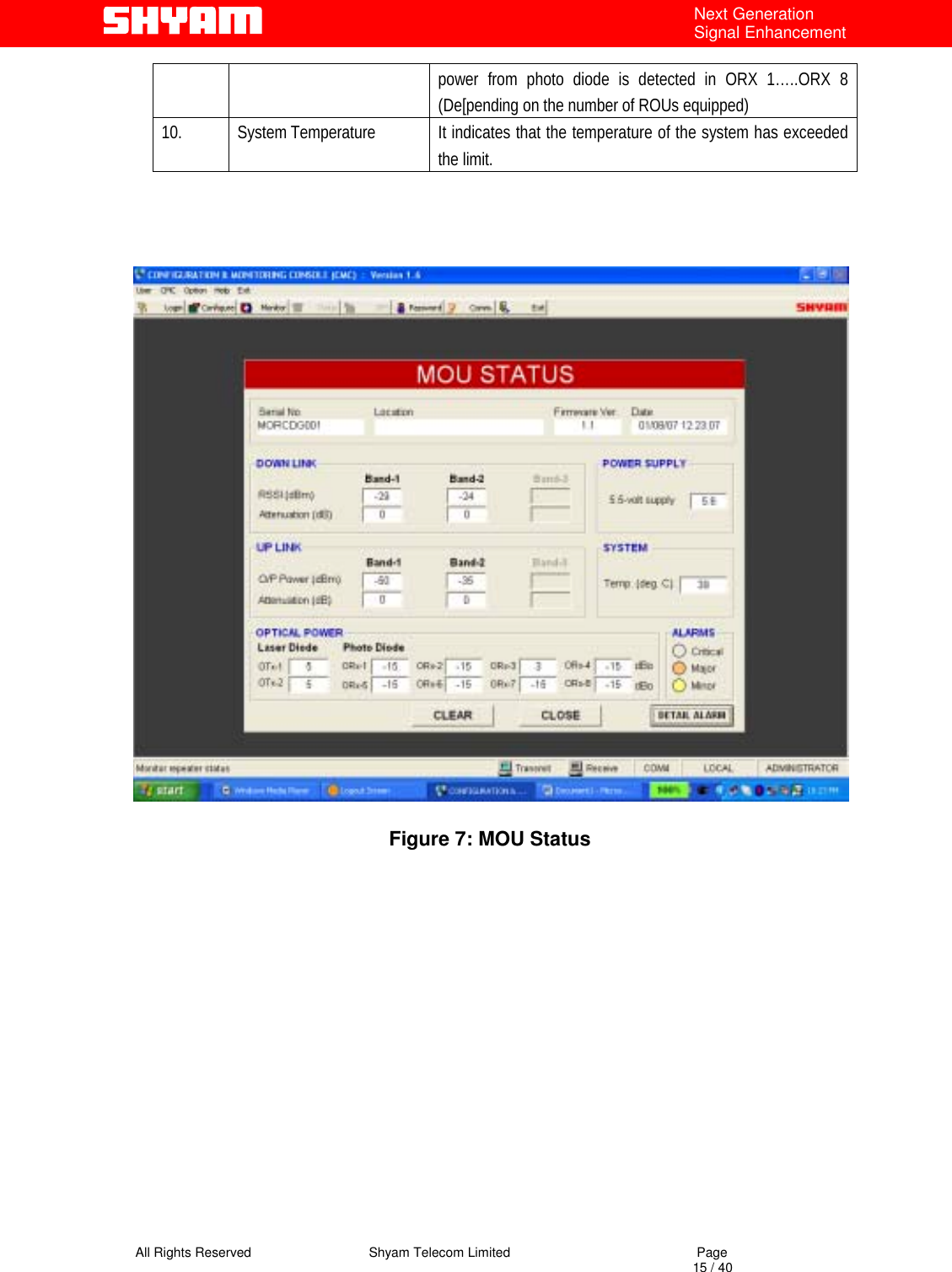
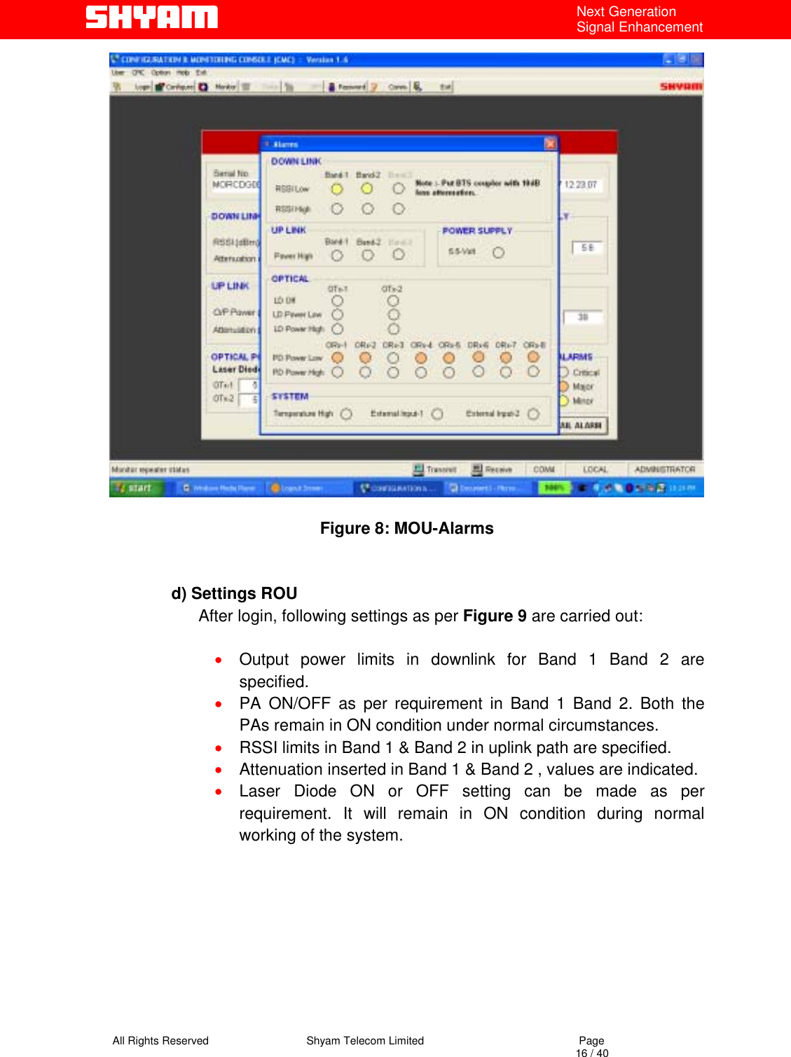
![All Rights Reserved Shyam Telecom Limited Page 13 / 40 Next Generation Signal Enhancement Downlink • RSSI Band 1 & Band 2 • Attenuation in Band 1 & Band 2 Uplink • Out put Power Band 1 & Band 2 • Attenuation in Band 1 & Band 2 Optical Power • OTX 1 & OTX 2 • ORX 1 to 8 [As per number of equipped DBROUs] Power Supply • 5.5 V Alarms • Alarms as per categorization viz. Critical, major & minor are set. Clicking at “detail alarms” can further check detail of alarms. Figure 5: MOU ID Settings](https://usermanual.wiki/Shyam-Telecom/BTSLINK-208.User-Manual-1/User-Guide-964140-Page-13.png)