Sensys Networks FLEXRAD FLEXRADIO CABINET User Manual APCC Installation Guide
Sensys Networks, Inc. FLEXRADIO CABINET APCC Installation Guide
Contents
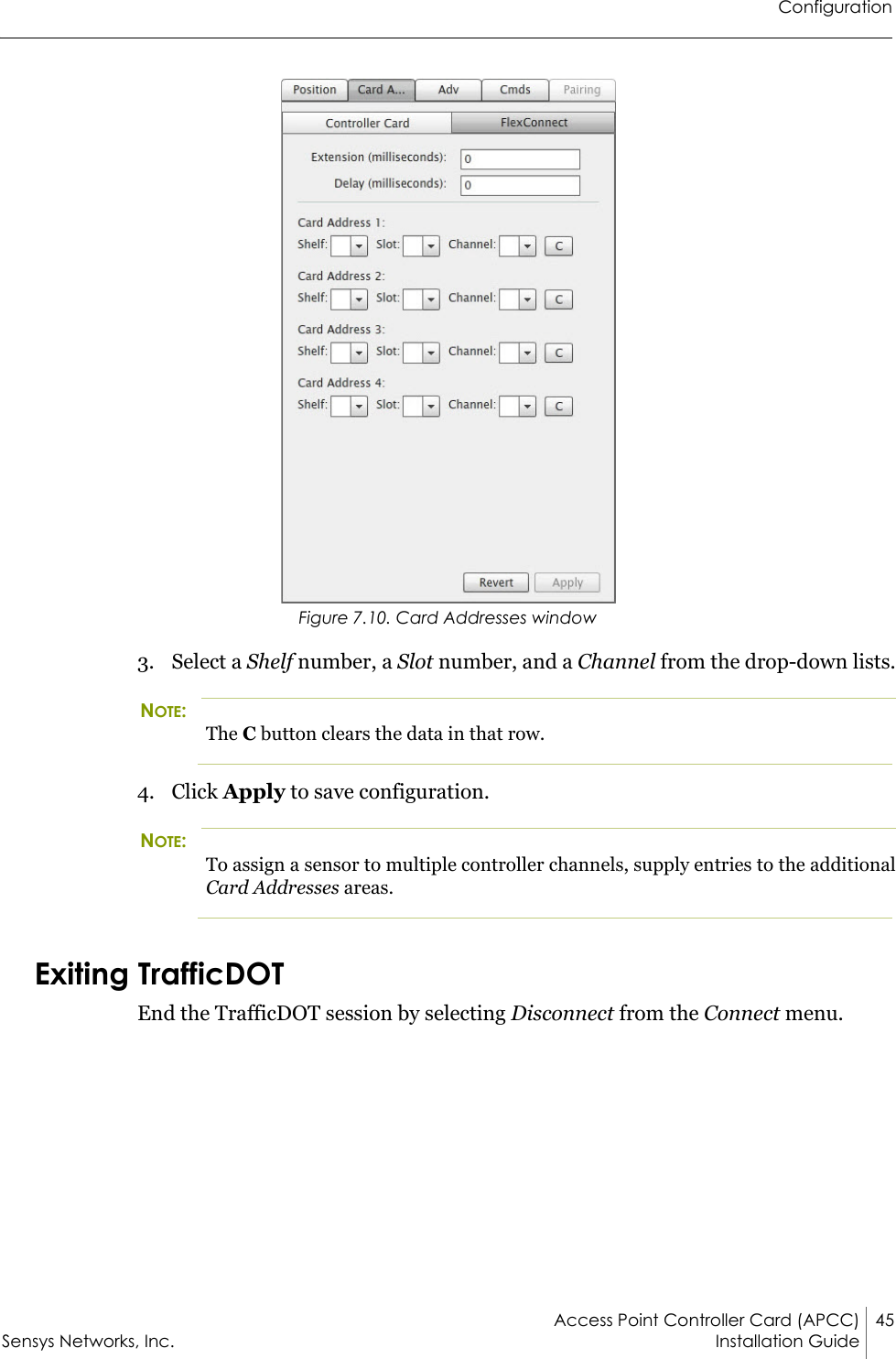
- 1. Installation Guide - Access Point Controller Card
- 2. Quick Start Guide
Installation Guide - Access Point Controller Card

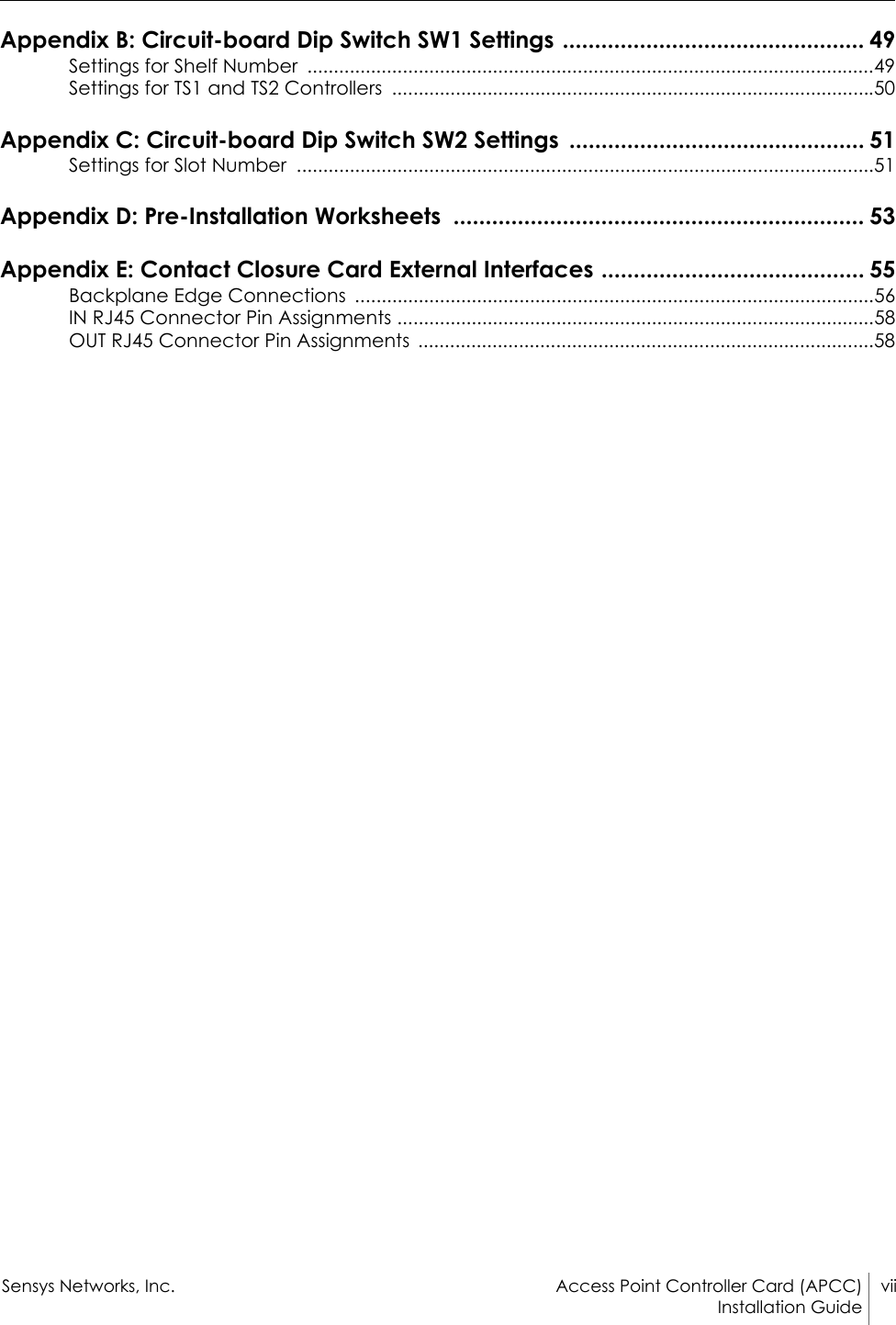

![Access Point Controller Card (APCC) 17Sensys Networks, Inc. Installation GuideChapter 5APCC Installation ProceduresThis chapter provides the instructions for installing and cabling an APCC.OverviewInstallation and setup of APCC occurs at the site of the traffic controller and consists of the following activities:Determining the Card ID and Setting it via Circuit-board Dip Switches SW1 and SW2Determining the Controller Type and Setting it via Circuit-board Dip Switch SW1Connecting the Cables to Each DeviceDetermining the Card ID and Setting it via Circuit-board Dip Switches SW1 and SW2APCC and EX cards are addressed via a value known as the Card ID. A Card ID must be unique to the network and is required for communication between the APCC and the EX cards.Card ID values are expressed as: [ shelf number ] - [ slot number ].Both shelf-number and slot-number must be determined to create a Card ID.Some traffic controllers designate the card address, while others (typically older models) do not. In the latter case, the installer assigns the Card ID ensuring that it is unique to the network.Follow the procedures in this section for each contact closure card to be installed.](https://usermanual.wiki/Sensys-Networks/FLEXRAD.Installation-Guide-Access-Point-Controller-Card/User-Guide-3455193-Page-25.png)


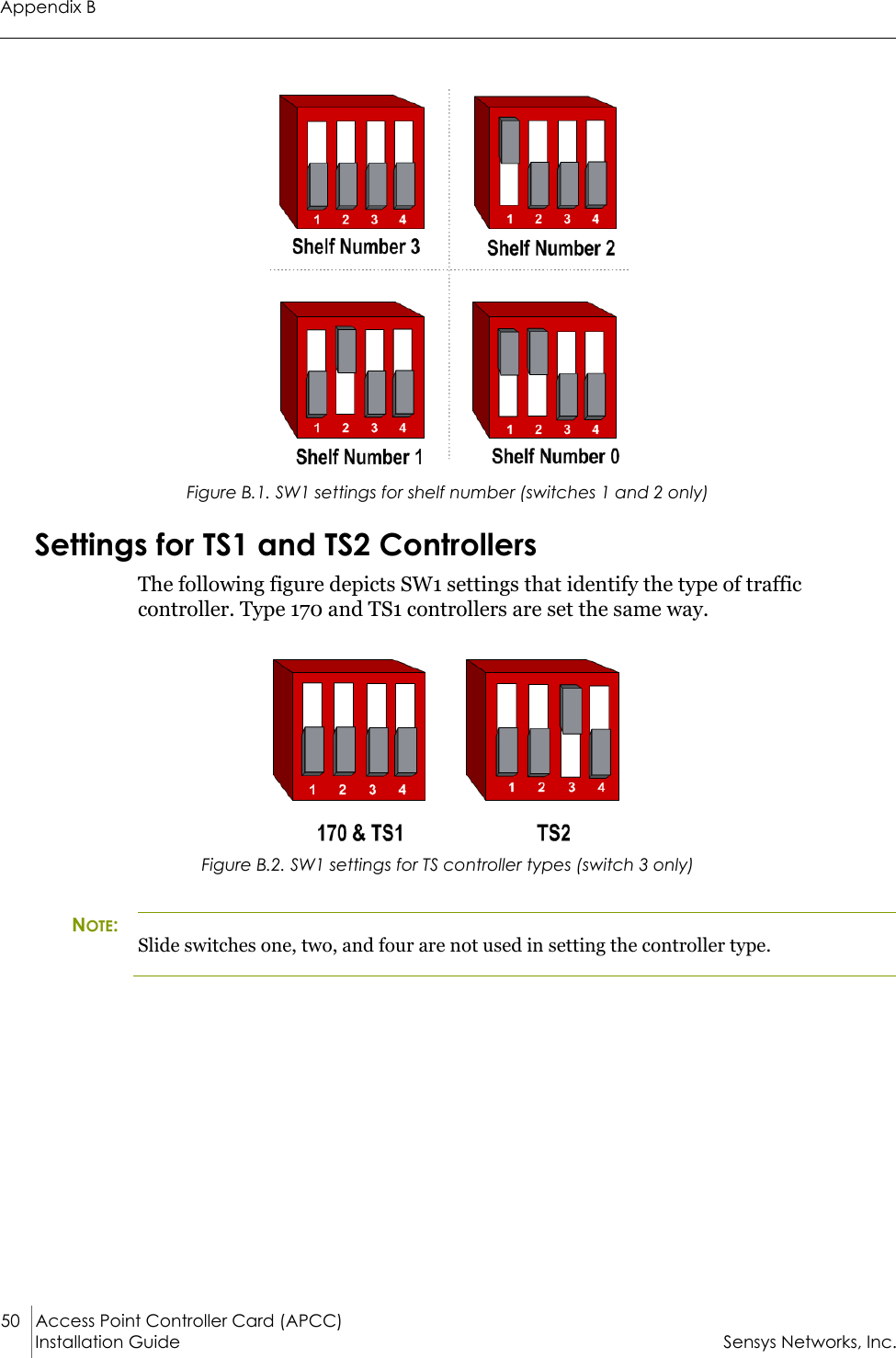
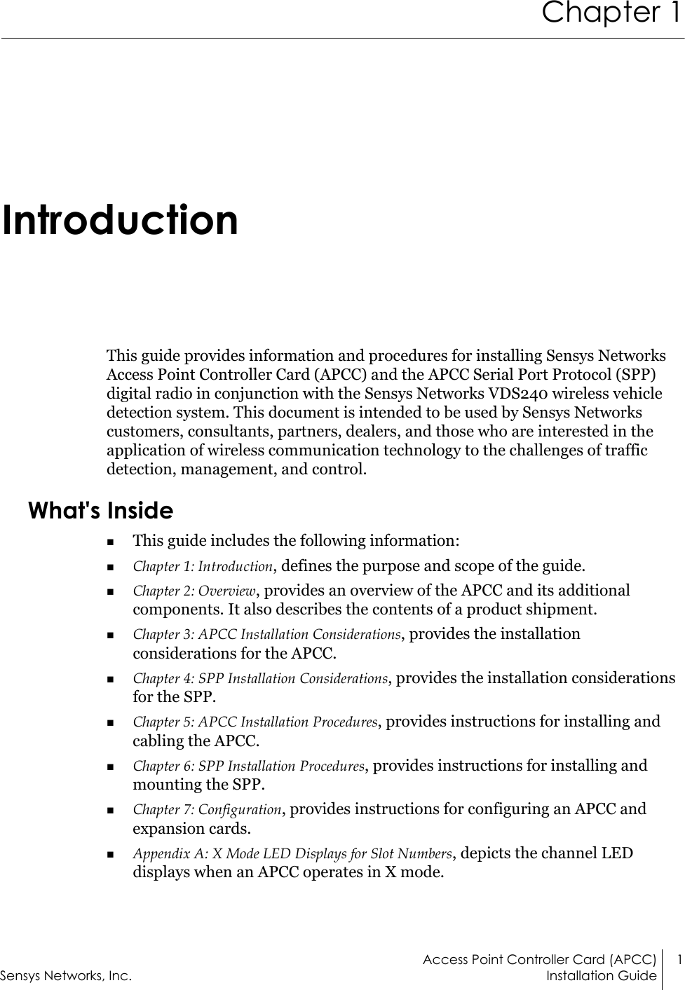
![Access Point Controller Card (APCC) 49Sensys Networks, Inc. Installation GuideAppendix BCircuit-board Dip Switch SW1 SettingsThis appendix depicts combinations of switch settings on the circuit-board dip switch SW1.Settings for Shelf NumberThe figure below depicts SW1 settings that identify the shelf number portion of the unique card address. NOTE:The small, slide switches are referred to by number [1-4] starting with the left-most switch. Switches three and four of SW1 are not used in setting the shelf number.](https://usermanual.wiki/Sensys-Networks/FLEXRAD.Installation-Guide-Access-Point-Controller-Card/User-Guide-3455193-Page-57.png)