Schweitzer Engineering Laboratories SEL3X21 SEL-3021 User Manual Copy 3021 01
Schweitzer Engineering Laboratories, Inc. SEL-3021 Copy 3021 01
UserManual.wiki
>
Schweitzer Engineering Laboratories
>
SEL3X21 User Manual
Users Manual
Navigation menu
Upload a User Manual
Namespaces
Wiki Guide
HTML
PDF
Info
Views
User Manual
Discussion / Help
Navigation
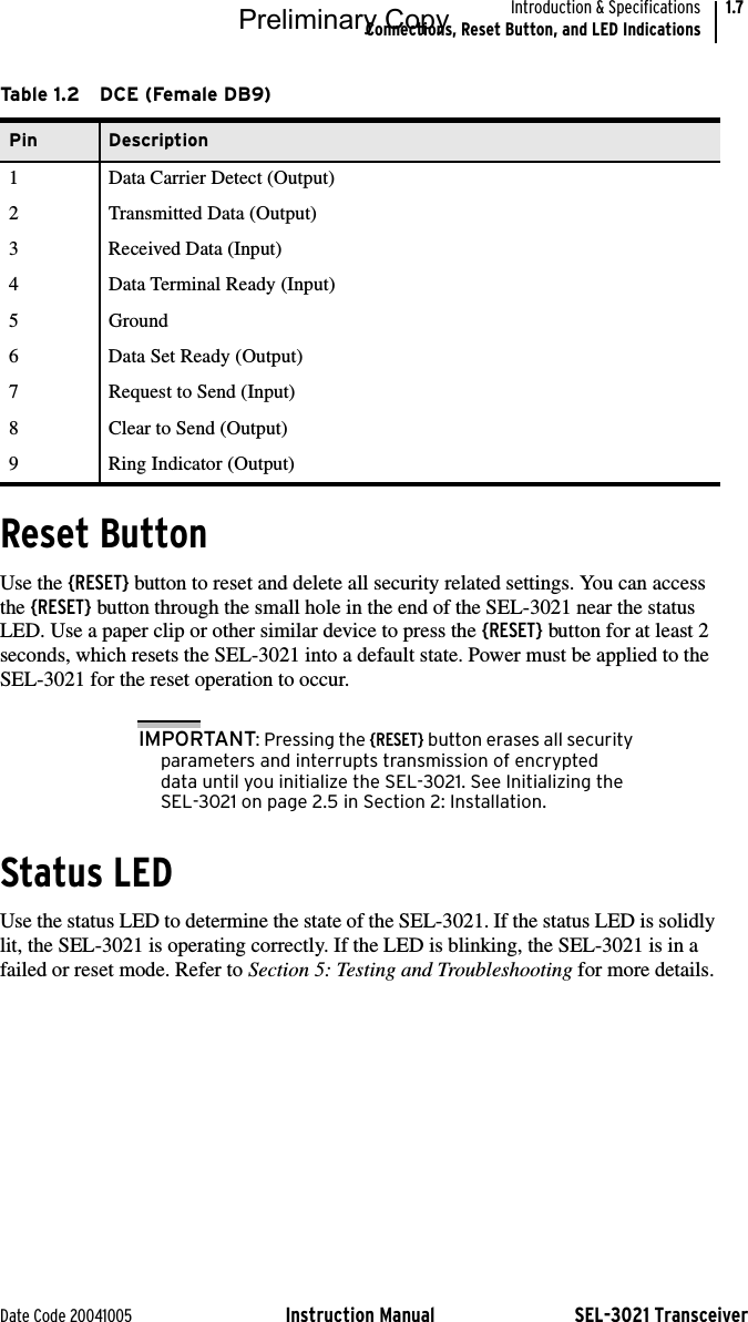
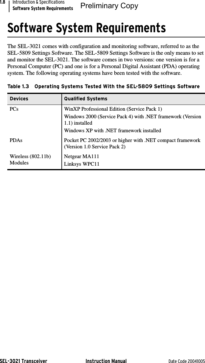
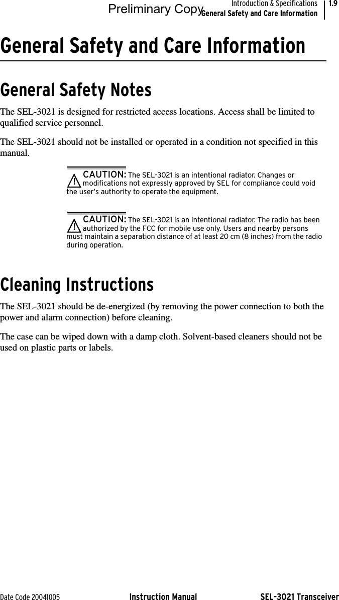
![SEL-3021 Transceiver Instruction Manual Date Code 20041005Introduction & SpecificationsSpecifications1.10SpecificationsIndicatorsGreen LED: Device StatusSolid-State Output100 mA continuous250 Vdc or 120 Vac Operational VoltageMax. On Resistance: 50 ΩMin. Off Resistance: 10 MΩInsulation: 1500 VdcWiring size: 14 AWG Max.26 AWG Min.0.4 mm Min. Insulation105° C, 250 V Min.Encryption ProtocolsAES: 128-bit encryptionSerial PortConnectors: DB-9 Male (DTE)DB-9 Female (DCE)Data Rate: 300 bps to 38400 bpsInterface: EIA-232Wi-Fi/802.11b Configuration PortProtocol: IEEE 802.11bModulation: DSSSFrequency Band: 2.4 GHzEncryption: 128-bit WEP and128-bit AESAuthentication: HMAC SHA-1 128-bit keyPower Requirements+5 to +24 Vdc: <5 Wsupplied through compression terminals or a 2.5 mm jackOperating Temperature Range–40° to +85°C (–40° to +185°F)802.11b module (0° to +70°C)5 to 95% humidity (noncondensing)Dimensions3.675" wide4.8" deep1" high, without DIN mountType TestsElectromagnetic CompatibilityRadiated Emissions: IEC 60255-25:2000, Class AFCC part 15 Class AElectromagnetic Compatibility ImmunityConducted RF Immunity: ENV 50141:1993, 10 V rmsIEC 61000-4-6:1996,10 V rmsDigital Radio Telephone RF: ENV 50204:1995, 10 V/m at 900 MHzand 1.89 GHzElectrostatic Discharge: IEC 60255-22-2:1996,IEC 61000-4-2:1999,[EN 61000-4-2–1995], Levels 1, 2, 3, 4Fast Transient Disturbance: IEC 61000-4-4:1995,IEC 60255-22-4:1992,4 kV at 2.5 and 5 kHzRadiated Radio Frequency: ENV 50140–1993,IEC 60255-22-3:1989, 10 V/mIEEE C37.90.2–1995,35 V/mType Test Compliance Criteria:1) The SEL-3021 does not damage or impede IED operation.2) The SEL-3021 is allowed to lose data during testing events.3) The SEL-3021 must recover without external intervention.EnvironmentalCold: IEC 60068-2-1:1990[EN 60068-2-1–1993], Test Ad: 16 hrs @ –40°CDry Heat: IEC 60068-2-2:1974[EN 60068-2-2–1993],Test Bd: 16 hrs @ +85°CDamp Heat, Cyclic: IEC 60068-2-30:1980,Test Db: +25° to +55°C, 6 cycles, 95% humidityVibration: IEC 60255-21-1:1988,Class 1IEC 60255-21-2:1988, Class 1IEC 60255-21-3:1993, Class 2Max. Altitude: 2000 mPreliminary Copy](https://usermanual.wiki/Schweitzer-Engineering-Laboratories/SEL3X21/User-Guide-479868-Page-10.png)