Schweitzer Engineering Laboratories SEL-8310 SEL-8310 User Manual Ranger IM
Schweitzer Engineering Laboratories, Inc. SEL-8310 Ranger IM
UserManual.wiki
>
Schweitzer Engineering Laboratories
>
SEL 8310 User Manual
User Manual
Navigation menu
Upload a User Manual
Namespaces
Wiki Guide
HTML
PDF
Info
Views
User Manual
Discussion / Help
Navigation
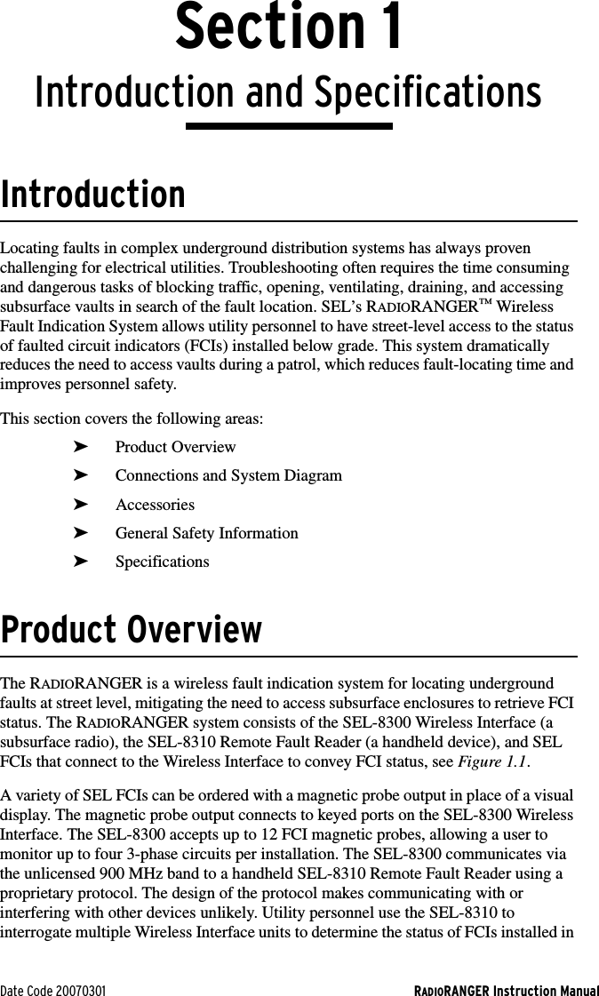
![RADIORANGER Instruction Manual Date Code 20070301Introduction and SpecificationsSpecifications1.4SpecificationsOperating Temperature Range–40° to +85°C (–40° to +185°F)5 to 95% humidity (noncondensing)Electromagnetic CompatibilityElectrostatic Discharge Immunity: IEC 60255-22-2: 1996 [EN 60255-22-2: 1997]IEC 61000-4-2: 1995 [EN 61000-4-2: 1995 + A1:1999 + A2:2001]IEEE C37.90.3: 2001Severity Level: 2, 4, 6, 8 kV contact discharge; 2, 4, 8, 15 kV air dischargeRadio FrequencyInterference Immunity: IEC 61000-4-3: 2002 [EN 61000-4-3: 2002]IEC 60255-22-3: 2000 [EN 60255-22-3: 2001]Severity Level: 10 V/mIEEE C37.90.2: 2004Severity Level: 35 V/mPower FrequencyMagnetic FieldImmunity: IEC 61000-4-8: 2001[EN 61000-4-8: 1994+ A1:2001]Severity Level: 100 A/m (60 Sec),1000 A/m (3 Sec),Level 5Pulse MagneticField Immunity: IEC 61000-4-9: 1993:2001 [EN 61000-4-9: 1994 + A1:2001]Severity Level: 1000 A/m, Level 5Damped OscillatoryMagnetic FieldImmunity: IEC 61000-4-10: 2001[EN 61000-4-10: 1994+ A1:2001]Severity Level:100 A/m, Level 5Radiated RadioFrequency: (900 MHz and 1.89 GHz with modulation): ENV 50204: 1995, 10 V/m Emissions: FCC Part 15, Class B EnvironmentalCold IEC 60068-2-1: 1990 + A1:1993 + A2:1994 [EN 60068-2-1:1993 + A2:1995]Temperature Shock on SEL-8310: MIL-STD-810F Method 503.4–40°C (–40°F) and +70°C (158°F) with temperature stabilized inside the unit.Dry Heat: IEC 60068-2-2: 1974+ A1:1993 + A2:1994[EN 60068-2-2: 1993+ A1:1995]Damp Heat, Cyclic: IEC 60068-2-30: 1980+ A1:1985 [EN 60068-2-30:1999]Vibration Resistance: IEC 60255-21-1: 1988[EN 60255-21-1: 1996+ A1:1996]VibrationEndurance: Severity Class 1VibrationResponse: Severity Class 2Shock Resistance: IEC 60255-21-2: 1988[EN 60255-21-2: 1996+ A1:1996]Bump Test: Severity Class 1Shock Withstand: Severity Class 1Shock Response: Severity Class 2](https://usermanual.wiki/Schweitzer-Engineering-Laboratories/SEL-8310/User-Guide-767193-Page-14.png)
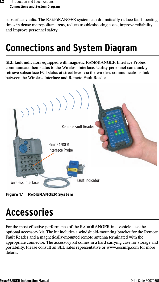
![Date Code 20070301 RADIORANGER Instruction ManualIntroduction and SpecificationsSpecifications1.5Seismic (QuakeResponse): IEC 60255-21-3: 1993[EN 60255-21-3: 1995+ A1:1995]Severity Level: Class 2IEC 60529: 2001+ CRDG:2003 [BS EN 60529:1992Protection Class+ REAF:2004]Severity Level: IP68 (4.5 m[15 feet]) SEL-8300 = IP54SEL-8310 = IP58CertificationsListings:](https://usermanual.wiki/Schweitzer-Engineering-Laboratories/SEL-8310/User-Guide-767193-Page-15.png)