Schneider Electric Systems Canada EB450-XXF01 Remote Radio Data Modem Base/Repeater User Manual EB Quick Start Guide pmd
Trio Datacom Pty Ltd (a wholly owned company of Schneider Electric) Remote Radio Data Modem Base/Repeater EB Quick Start Guide pmd
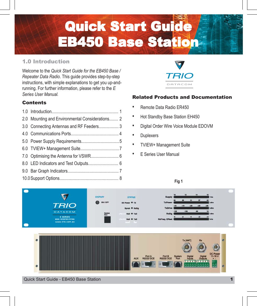
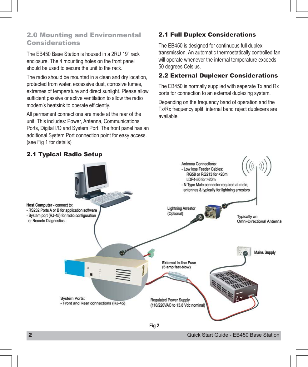
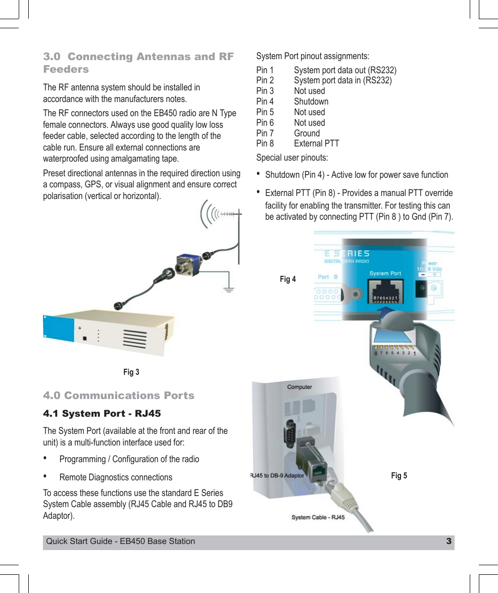
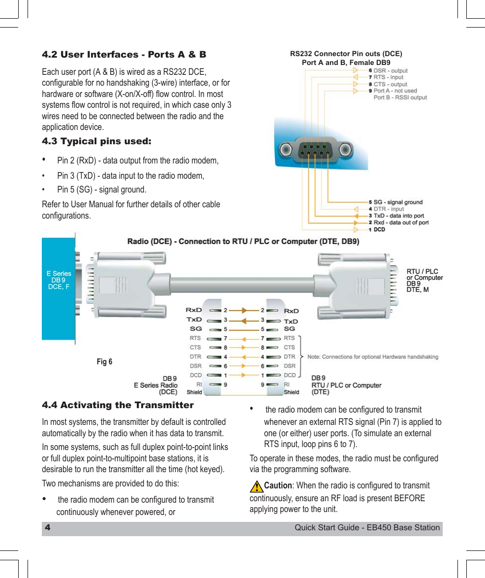
Contents
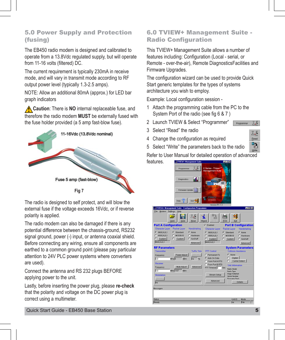
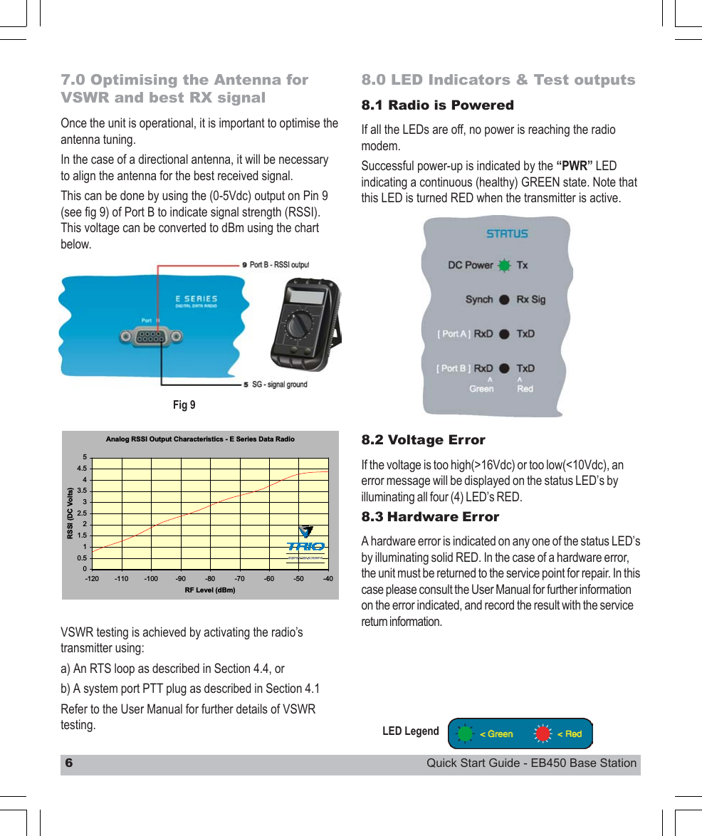
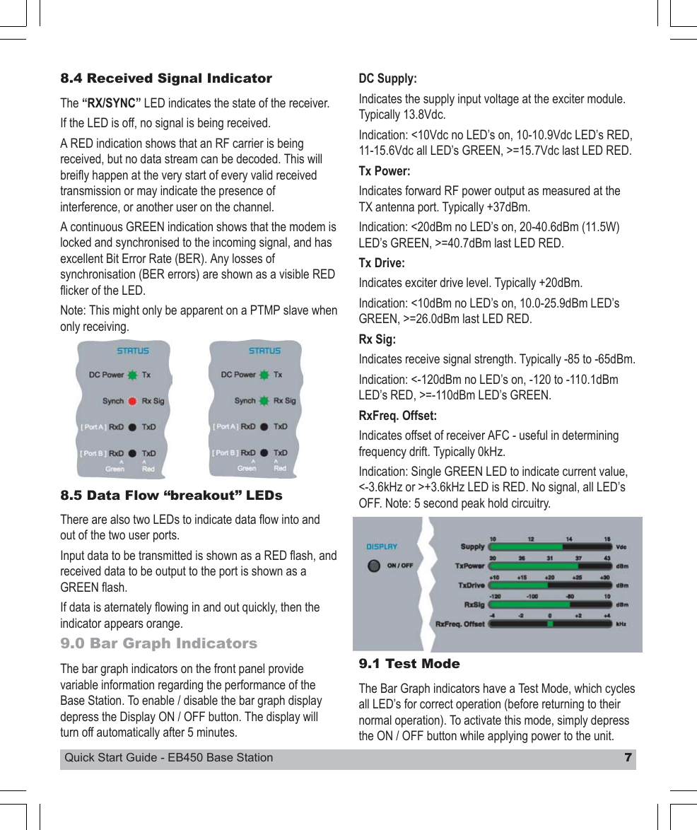
EB Quick Start Guide