Sanyo Electric Co CPE-310-200 W-CDMA subscriber terminal User Manual odsp3
Sanyo Electric Co Ltd W-CDMA subscriber terminal odsp3
UserManual.wiki
>
Sanyo Electric Co
>
CPE-310-200 User Manual
>
User manual part 2
Contents
1.
Quick reference guide
2.
User manual part 1
3.
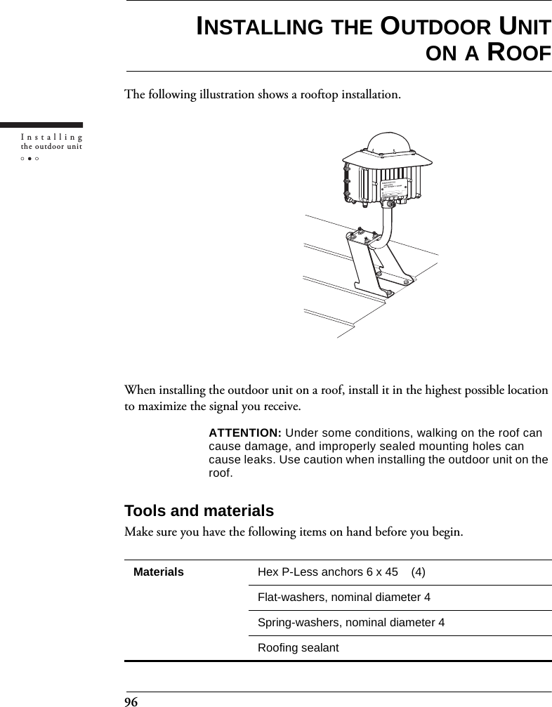
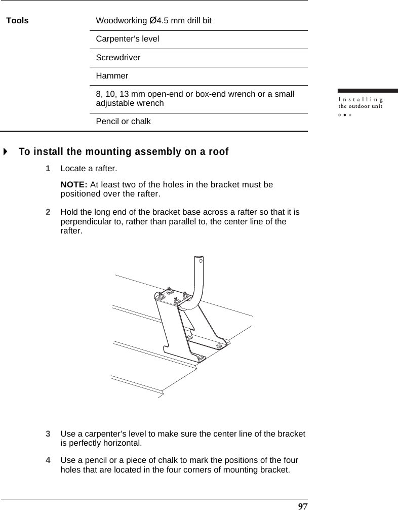
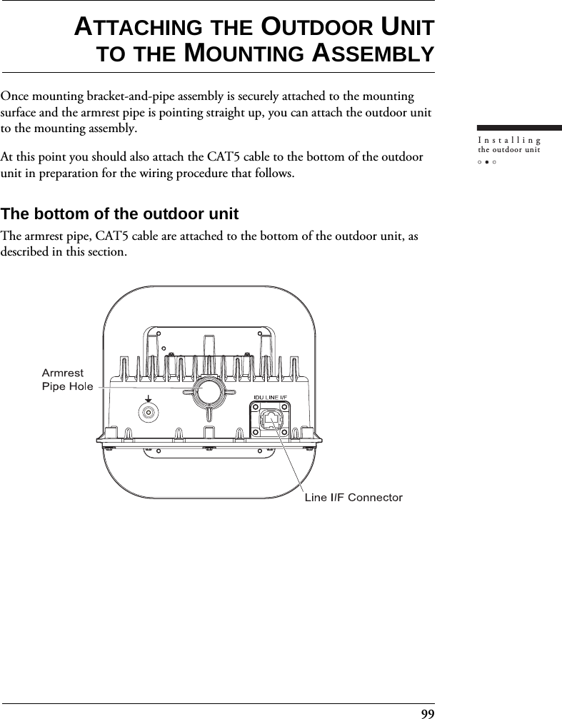
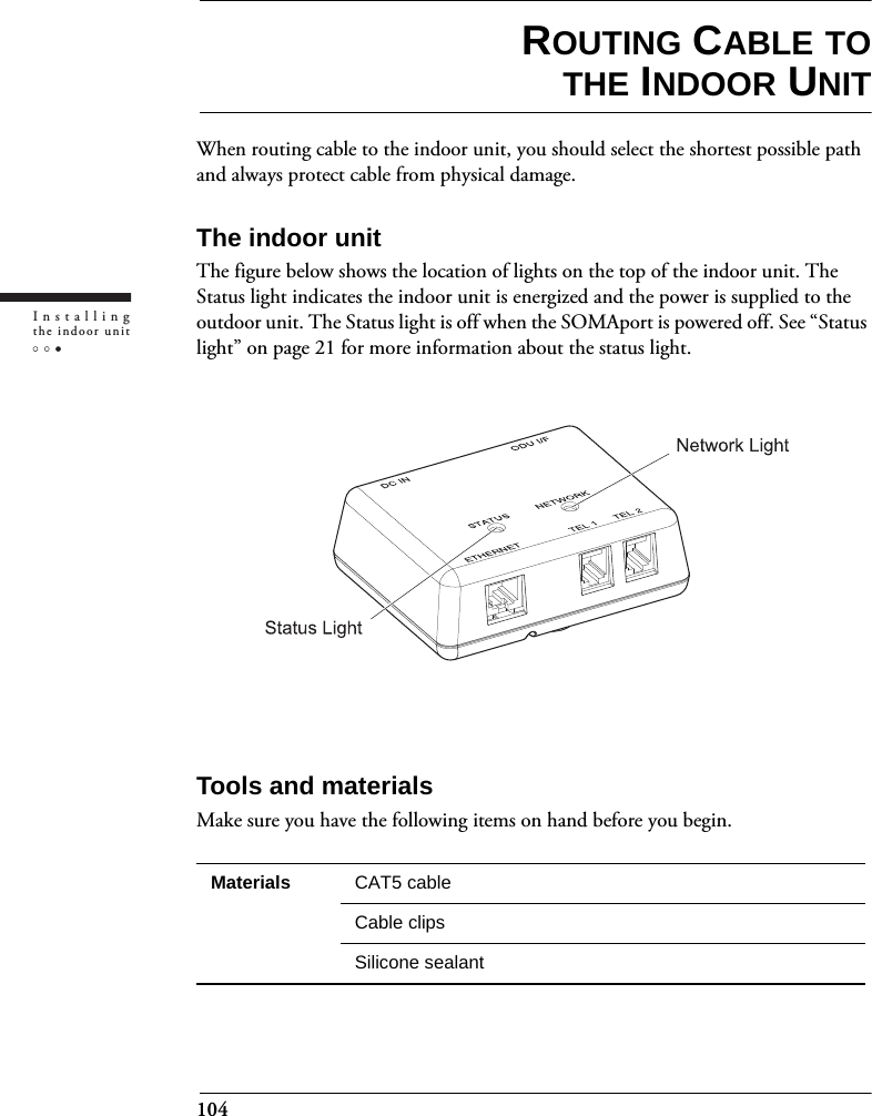
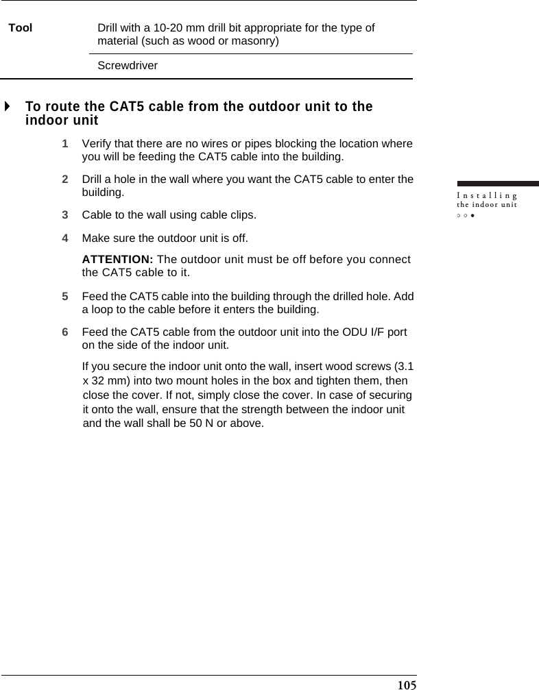
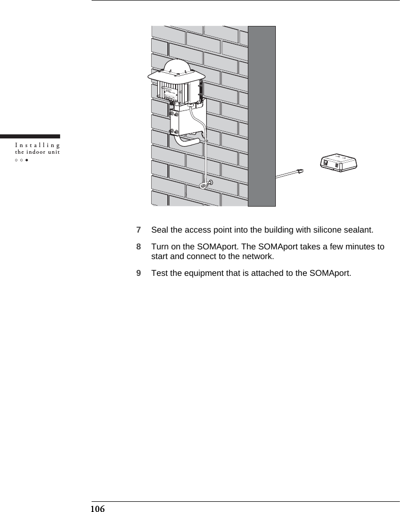
User manual part 2
User manual part 2
Navigation menu
Upload a User Manual
Namespaces
Wiki Guide
HTML
PDF
Info
Views
User Manual
Discussion / Help
Navigation