Samsung Electronics Co RFD01P-13A RRU (RFD01P) Base Station User Manual 2 Installation
Samsung Electronics Co Ltd RRU (RFD01P) Base Station 2 Installation
UserManual.wiki
>
Samsung Electronics Co
>
RFD01P-13A User Manual
>
User Manual-2 Installation
Contents
1.
User Manual-1 Description
2.
User Manual-2 Installation
User Manual-2 Installation
Navigation menu
Upload a User Manual
Namespaces
Wiki Guide
HTML
PDF
Info
Views
User Manual
Discussion / Help
Navigation
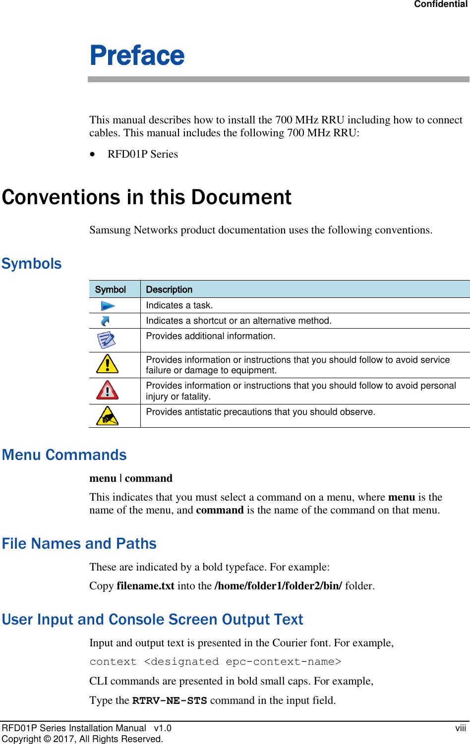
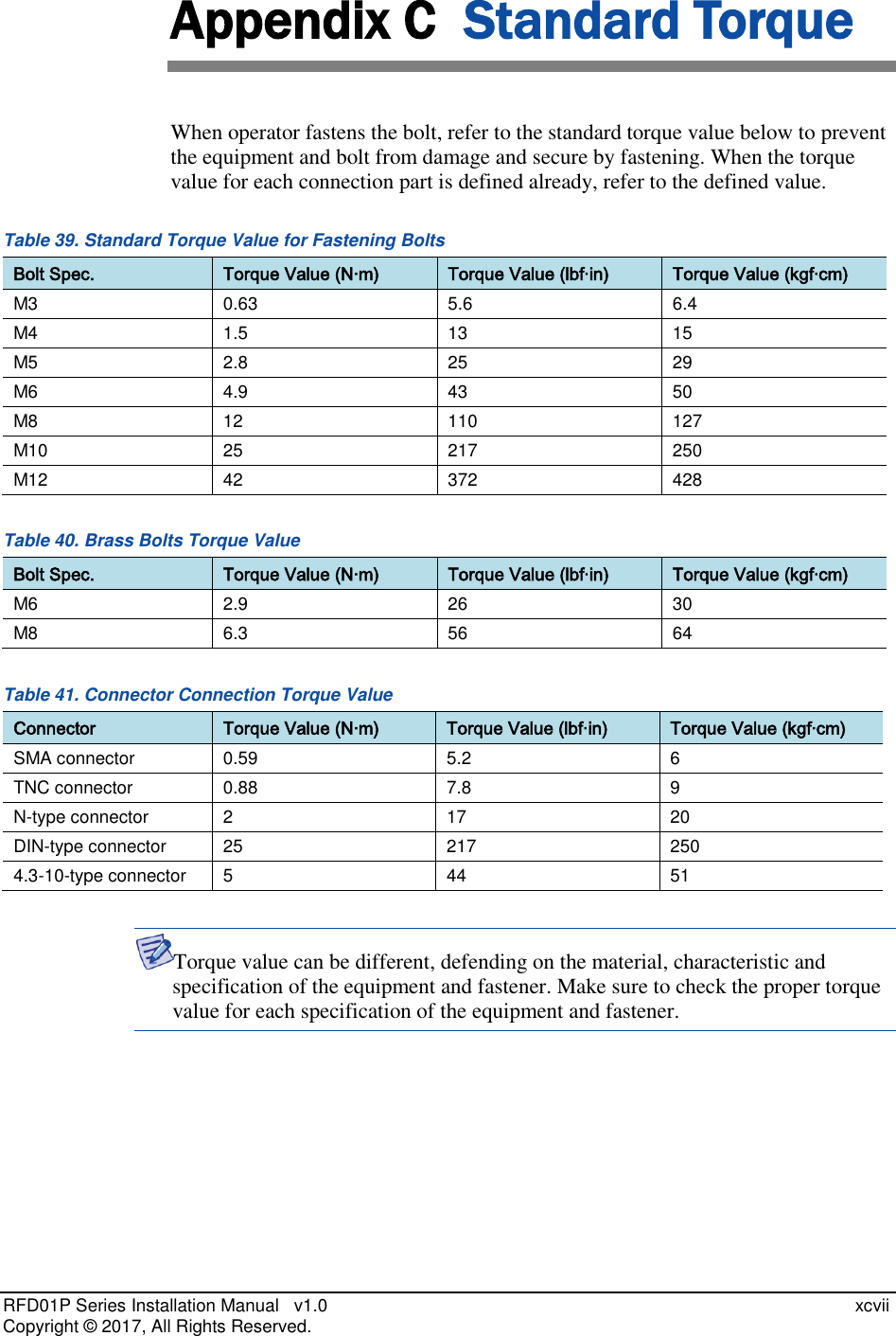
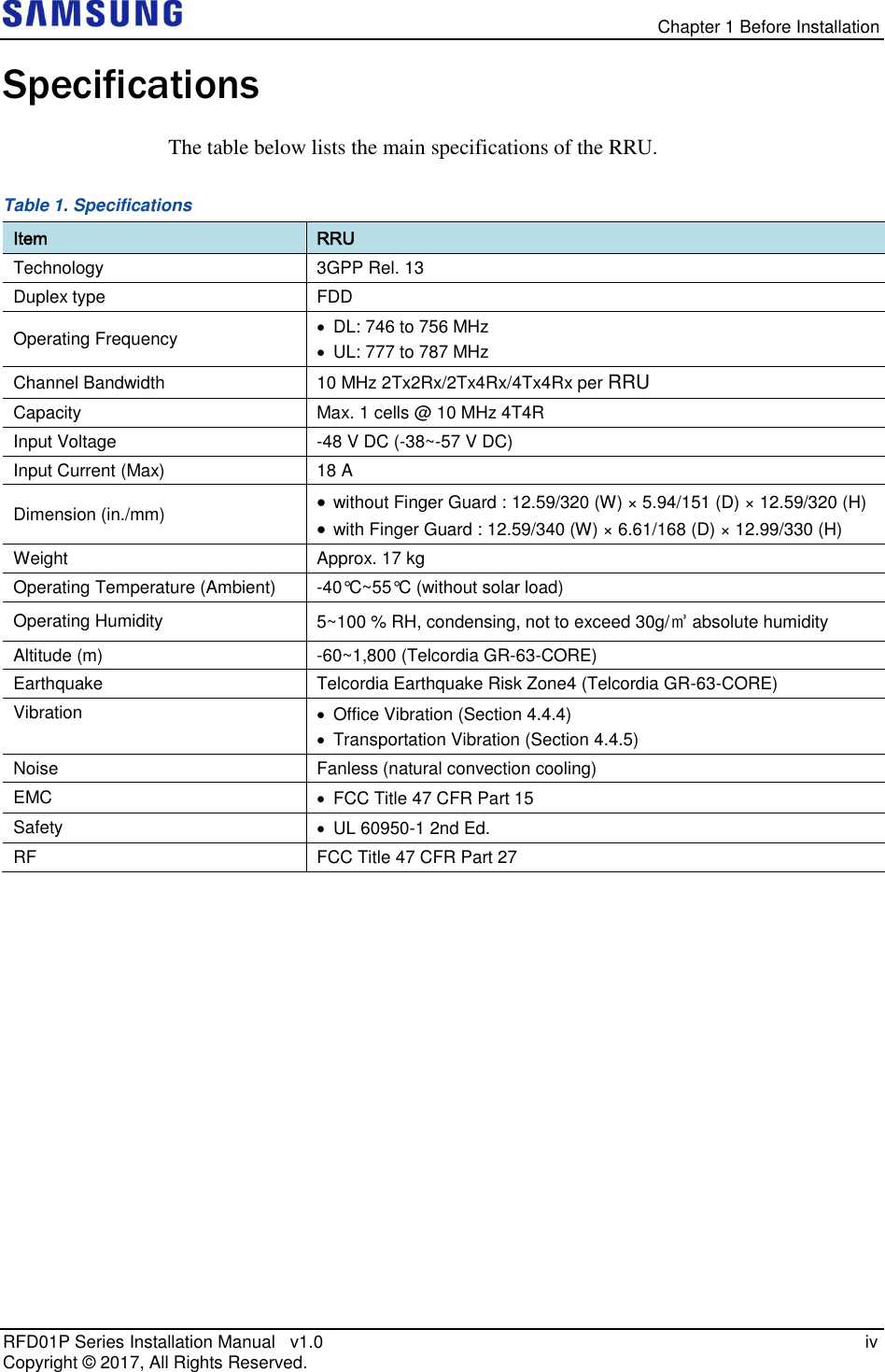
![Confidential RFD01P Series Installation Manual v1.0 i Copyright © 2017, All Rights Reserved. Chapter 1 Before Installation System Configuration and Interface RRU Configuration The configuration of RRU is as follows. Figure 1. Configuration (without Finger Guard) [Bottom View] 12.59 (320) [Front View] [Top View] [Left View] [Right View] [Rear View] 15.09 (383) 5.94 (151) 12.59 (320) Unit: in. (mm)](https://usermanual.wiki/Samsung-Electronics-Co/RFD01P-13A.User-Manual-2-Installation/User-Guide-3423645-Page-15.png)
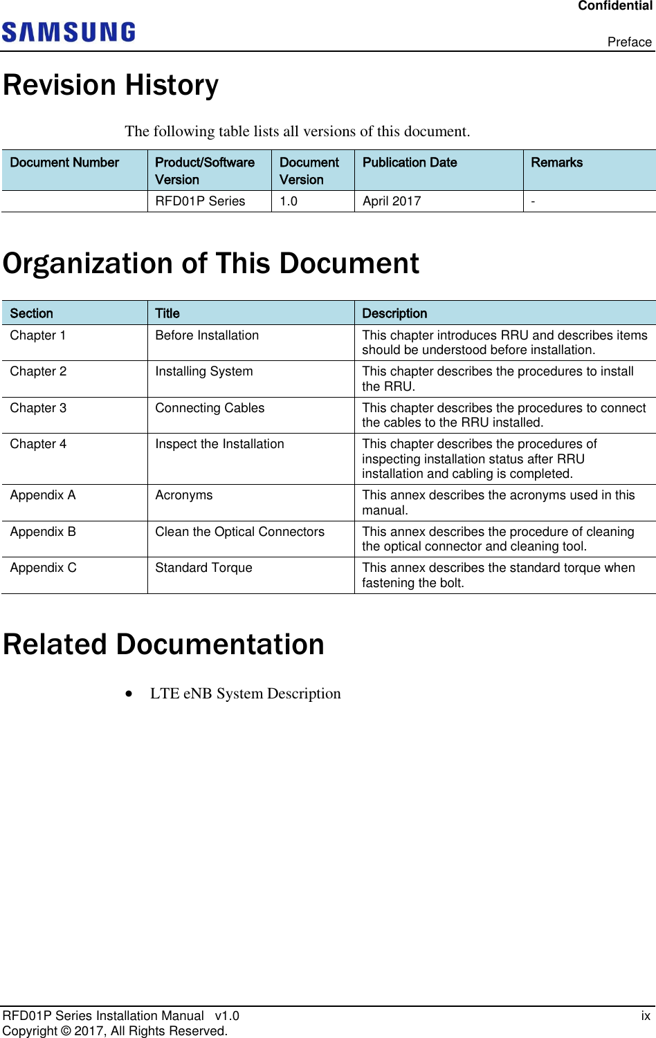
![Chapter 1 Before Installation RFD01P Series Installation Manual v1.0 ii Copyright © 2017, All Rights Reserved. Figure 2. RRU Configuration (with Finger Guard) [Bottom View] 12.99 (330) [Front View] [Top View] [Left View] [Right View] [Rear View] 15.47 (393) 6.61 (168) 13.38 (340) Unit: in. (mm)](https://usermanual.wiki/Samsung-Electronics-Co/RFD01P-13A.User-Manual-2-Installation/User-Guide-3423645-Page-16.png)
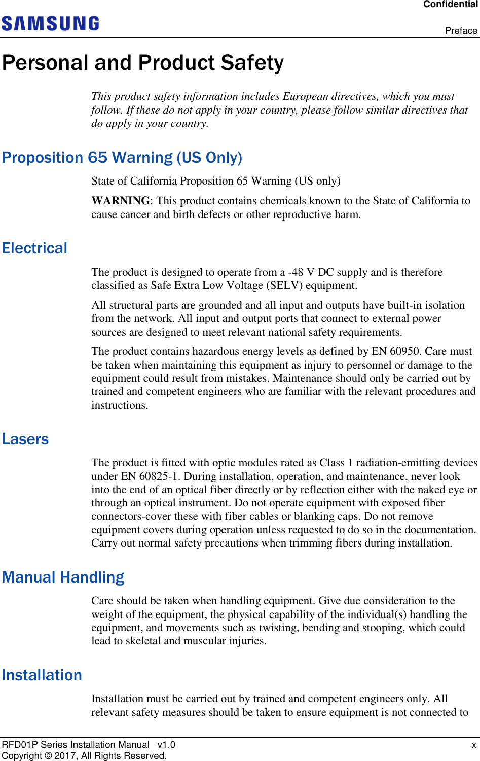
![Chapter 1 Before Installation RFD01P Series Installation Manual v1.0 iii Copyright © 2017, All Rights Reserved. RRU Interface The interface structure of RRU is as follows. Figure 3. RRU Interface ANT 1 (Bias-T) [Bottom View] Ground Terminal RET ANT 2 ANT 3 (Bias-T) ANT 4 Front UDA L0 (CPRI_0) L1 (CPRI_1) DC_PWR](https://usermanual.wiki/Samsung-Electronics-Co/RFD01P-13A.User-Manual-2-Installation/User-Guide-3423645-Page-17.png)
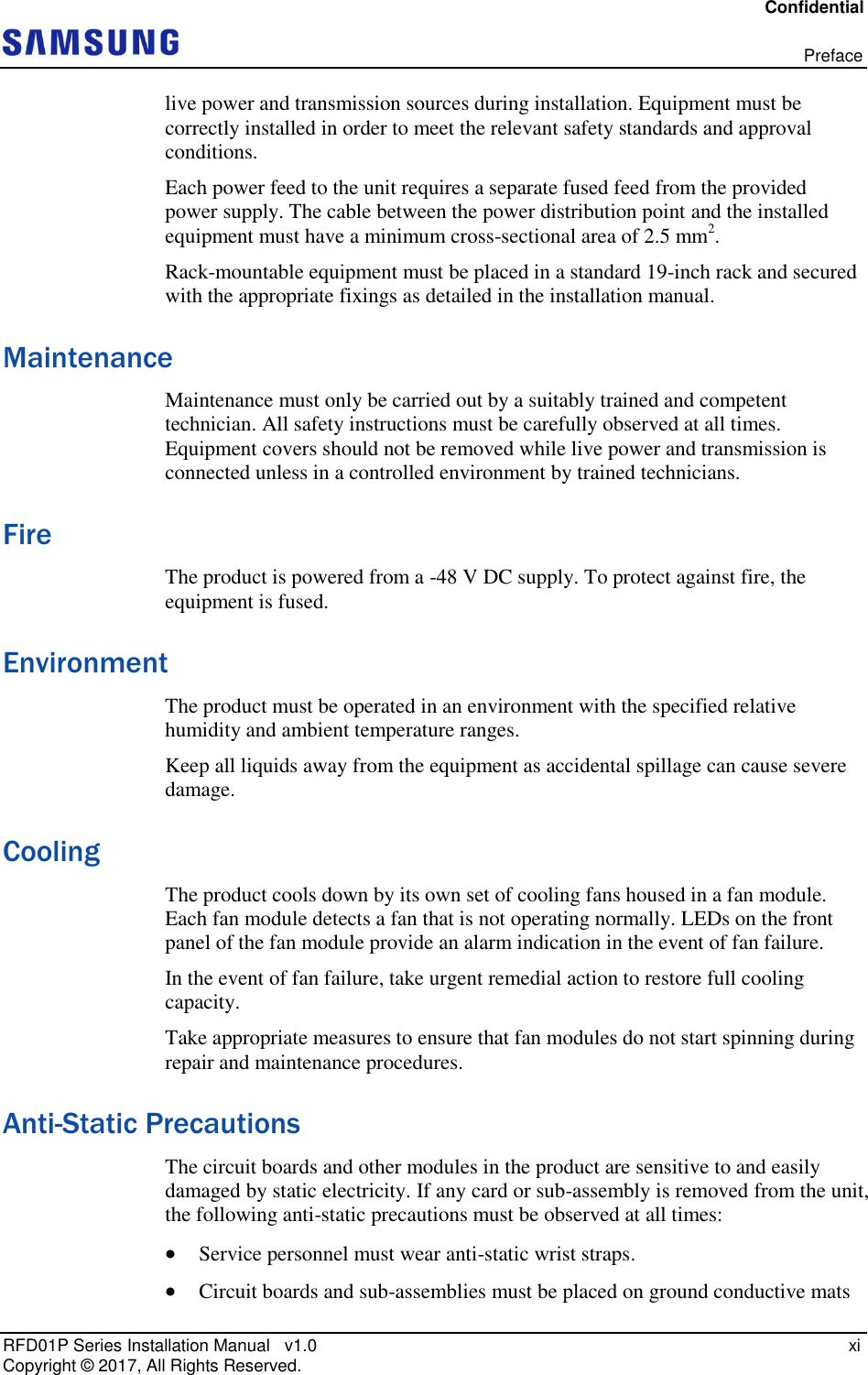
![Chapter 2 Installing System RFD01P Series Installation Manual v1.0 xi Copyright © 2017, All Rights Reserved. System Arrangement A minimum distance must be secured around the RRU, in each direction for installation and maintenance. Figure 5. RRU Arrangement_1Sector Pole Type Installation [Front View] [Side Installation] [Standard Installation] Unit: in. (mm) [Top View] [Side View] [Top View] ≥12 (300) ≥15.74 (400) ≥8 (200) ≥8 (200) 15.23 (387) ≥32 (800) ≥12 (300) ≥15.74 (400) ≥8 (200) ≥8 (200) 21.77 (553) ≥32 (800) Front Front W : 13.38 (340) H : 15.47 (393) D : 6.61 (168) H : 15.47 (393)](https://usermanual.wiki/Samsung-Electronics-Co/RFD01P-13A.User-Manual-2-Installation/User-Guide-3423645-Page-25.png)
![Chapter 2 Installing System RFD01P Series Installation Manual v1.0 xii Copyright © 2017, All Rights Reserved. Figure 6. RRU Arrangement_3Sector Pole Type Installation When fixing a pole mounting bracket, the length of a carriage bolt is 220 mm for the pole diameter 50~100 A. Pole Size Pole Size Carriage Bolt Carriage Bolt [1Sector] [3Sector] Pole Size(Diameter) Length of Carriage Bolt 50 A(60.5 mm) 220 mm 65 A(76.3 mm) 80 A(89.2 mm) 90 A(101.6 mm) 100 A(114.3 mm) [Side View] [Side Installation] Unit: in. (mm) [Top View] ≥12 (300) ≥15.74 (400) ≥8 (200) ≥8 (200) 21.77 (553) ≥32 (800) D : 20 (508) H : 15.47 (393)](https://usermanual.wiki/Samsung-Electronics-Co/RFD01P-13A.User-Manual-2-Installation/User-Guide-3423645-Page-26.png)
![Chapter 2 Installing System RFD01P Series Installation Manual v1.0 xiii Copyright © 2017, All Rights Reserved. Figure 7. RRU Arrangement_1Sector Wall Type Installation [Front View] [Side Installation] [Standard Installation] Unit: in. (mm) [Top View] [Side View] [Top View] ≥12 (300) ≥8 (200) 10.17 (258.5) ≥32 (800) 16.71 (424.5) ≥32 (800) Front Front ≥15.74 (400) ≥8 (200) ≥8 (200) ≥8 (200) ≥12 (300) ≥15.74 (400) W : 13.38 (340) H : 15.47 (393) D : 6.61 (168) H : 15.47 (393)](https://usermanual.wiki/Samsung-Electronics-Co/RFD01P-13A.User-Manual-2-Installation/User-Guide-3423645-Page-27.png)
![Chapter 2 Installing System RFD01P Series Installation Manual v1.0 xiv Copyright © 2017, All Rights Reserved. Figure 8. RRU Arrangement_3Sector Wall Type Installation [Front View] [Side Installation] [Standard Installation] Unit: in. (mm) [Top View] [Side View] [Top View] ≥12 (300) 16.71 (424.5) ≥32 (800) Front Front ≥32 (800) ≥8 (200) ≥12 (300) ≥15.74 (400) D : 20 (508) H : 15.47 (393) ≥8 (200) ≥8 (200) ≥8 (200) ≥15.74 (400) W : 55.90 (1420) / H : 15.47 (393) 10.17 (258.5) ≥8 (200) ≥8 (200)](https://usermanual.wiki/Samsung-Electronics-Co/RFD01P-13A.User-Manual-2-Installation/User-Guide-3423645-Page-28.png)
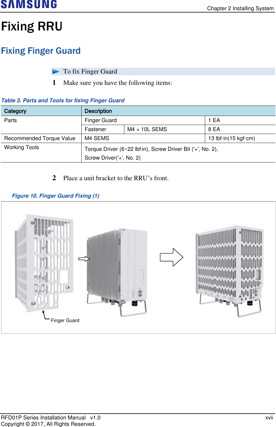
![Chapter 2 Installing System RFD01P Series Installation Manual v1.0 xviii Copyright © 2017, All Rights Reserved. 3 Fix RRU and finger guard using fasteners. Figure 11. Finger Guard Fixing (2) [Front] [Right] [Left] M4 SEMS M4 SEMS M4 SEMS](https://usermanual.wiki/Samsung-Electronics-Co/RFD01P-13A.User-Manual-2-Installation/User-Guide-3423645-Page-32.png)
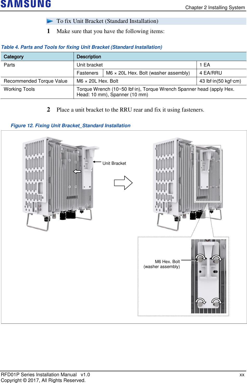
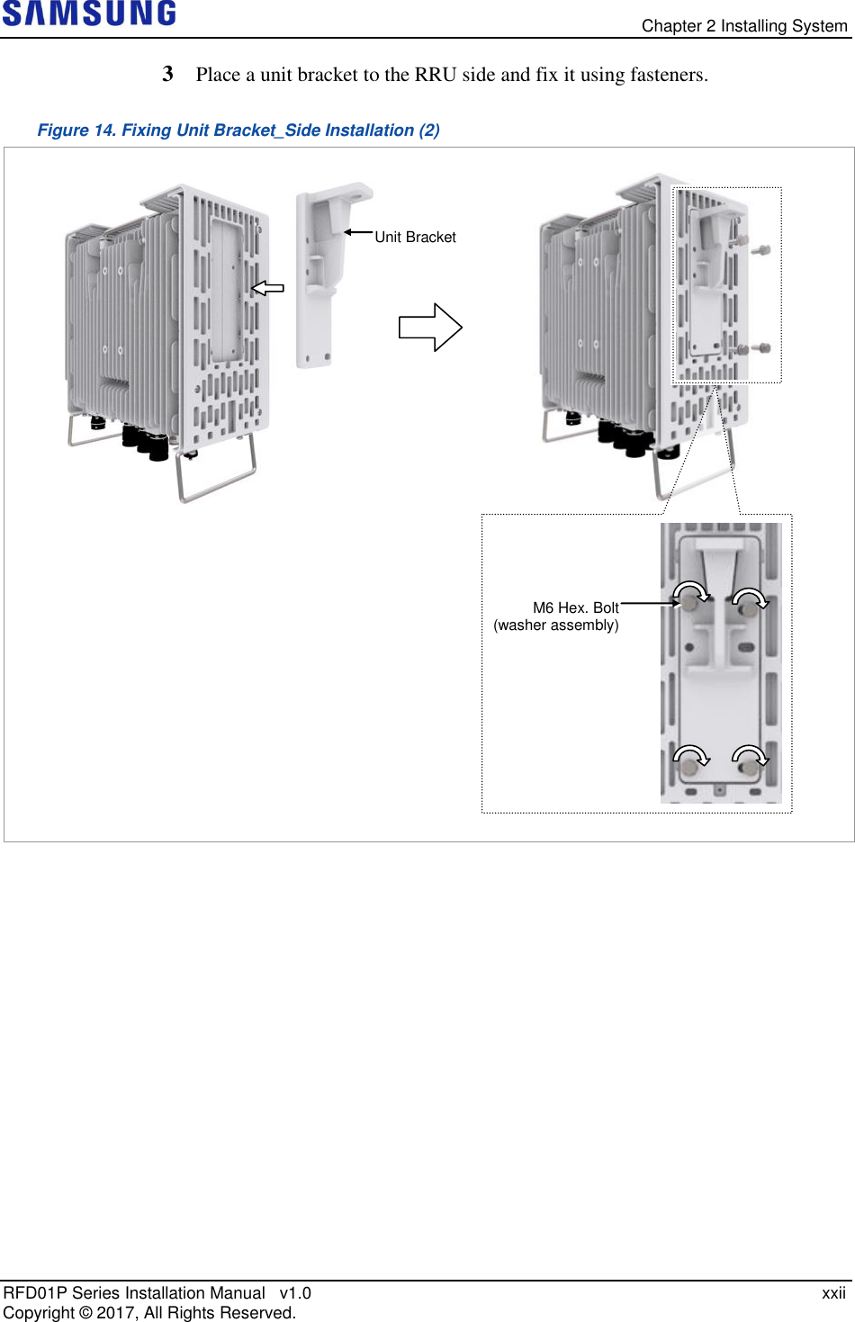
![Chapter 2 Installing System RFD01P Series Installation Manual v1.0 xix Copyright © 2017, All Rights Reserved. Fixing Unit Bracket There are two ways to fix a unit bracket to the RRU. One is fixing a unit mounting bracket to the rear side of RRU (Standard installation). The other is fixing a unit bracket to the side of RRU (Side installation). These are the same for the wall type and pole type installation procedures. [Unit Bracket Standard Installation] [Unit Bracket Side Installation] Front Front Unit Bracket rear Unit Bracket left side](https://usermanual.wiki/Samsung-Electronics-Co/RFD01P-13A.User-Manual-2-Installation/User-Guide-3423645-Page-33.png)
![Chapter 2 Installing System RFD01P Series Installation Manual v1.0 xxi Copyright © 2017, All Rights Reserved. To fix Unit Bracket (Side Installation) 1 Make sure that you have the following items: Table 5. Parts and Tools for fixing Unit Bracket (Side Installation) Category Description Parts Unit bracket 1 EA Fasteners M6 × 20L Hex. Bolt (washer assembly) 4 EA/RRU Recommended Torque Value M6 × 20L Hex. Bolt 43 lbfin(50 kgf·cm) Working Tools Screw Driver('+', No. 2), Torque Wrench (10~50 lbfin), Torque Wrench Spanner head (apply Hex. Head: 10 mm), Spanner (10 mm) 2 Loosen a fastener of the finger guard left side and separate the dummy cover from the system. Figure 13. Fixing Unit Bracket_Side Installation (1) Dummy Cover M3 Screw [Left View]](https://usermanual.wiki/Samsung-Electronics-Co/RFD01P-13A.User-Manual-2-Installation/User-Guide-3423645-Page-35.png)
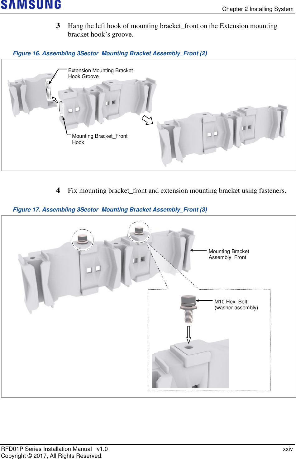
![Chapter 2 Installing System RFD01P Series Installation Manual v1.0 xxiii Copyright © 2017, All Rights Reserved. Assembling 3Sector Mounting Bracket Assembly_Front Assemble the 3sector mounting bracket assembly_front before installing 3sector system. The method for assembling the pole type is identical to it of wall type. To assemble 3Sector Mounting Bracket Assembly_Front 1 Make sure that you have the following items: Table 6. Parts and Tools for assembling 3Sector Mounting Bracket Assembly_Front Category Description Parts Mounting Bracket_Front 1 EA Extension Mounting Bracket 2 EA Fastener M10 × 25L Hex. Bolt(washer assembly) 2 EA Recommended Torque Value M10 Hex. Bolt 217 lbf·in(250 kgf·cm) Working Tools Torque Wrench (100~400 lbf·in), Torque Wrench Spanner head (apply Hex. Head: 17 mm), Spanner (17 mm) 2 Hang the right hook of mounting bracket_front on the Extension mounting bracket hook groove. Figure 15. Assembling 3Sector Mounting Bracket Assembly_Front (1) Mounting Bracket_Front Hook Extension Mounting Bracket Hook Groove [3Sector Mounting Bracket Assembly_Front]](https://usermanual.wiki/Samsung-Electronics-Co/RFD01P-13A.User-Manual-2-Installation/User-Guide-3423645-Page-37.png)
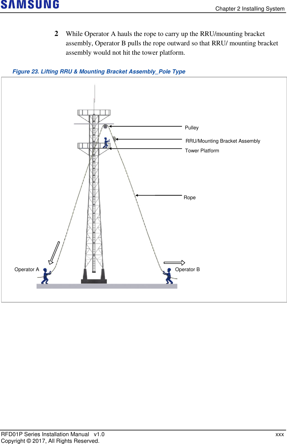
![Chapter 2 Installing System RFD01P Series Installation Manual v1.0 xxix Copyright © 2017, All Rights Reserved. Lifting RRU & Mounting Bracket Assembly To lift RRU/Mounting Bracket Assembly 1 Tie the rope in two carrying points of RRU and Mounting bracket assembly. The method for lifting 1sector is identical to it of 3sector. Figure 22. Lifting RRU & Mounting Bracket Assembly_Pole Type [Lifting 1Sector Mounting Bracket Assembly] [Lifting RRU] Carrying Point_1 Carrying Point_2 Carrying Point_1 Carrying Point_2](https://usermanual.wiki/Samsung-Electronics-Co/RFD01P-13A.User-Manual-2-Installation/User-Guide-3423645-Page-43.png)
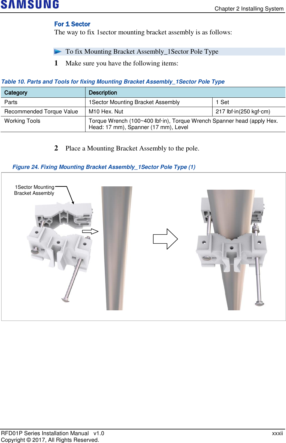
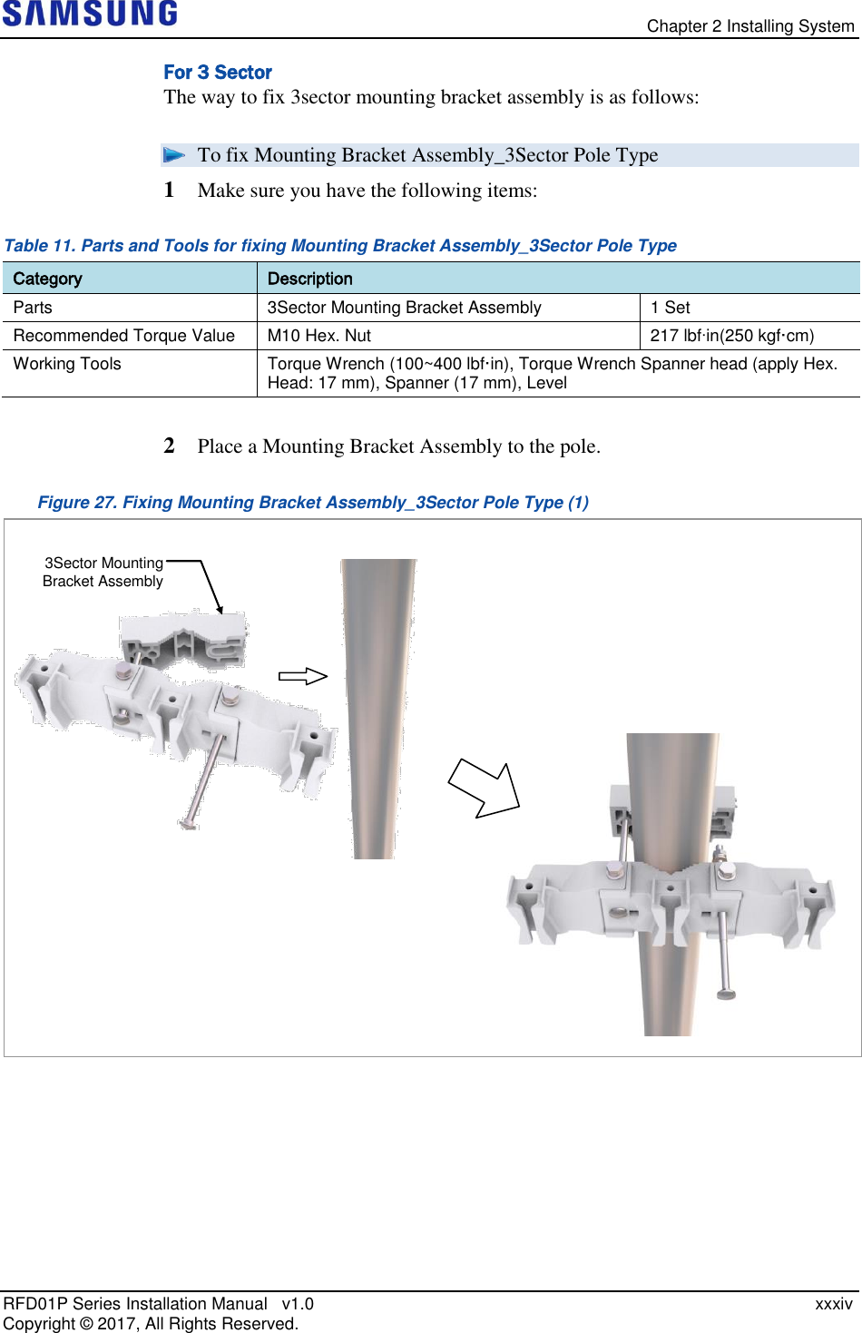
![Chapter 2 Installing System RFD01P Series Installation Manual v1.0 xxxi Copyright © 2017, All Rights Reserved. Fixing Mounting Bracket Assembly Check the Mounting Bracket_front type per installation type and sector type before installing the Mounting bracket. Table 9. Mounting Bracket type per installation type and sector type_Pole Type Sector Type Installation Type Bracket Type Unit 1Sector Standard Installation Mounting Bracket_Front 1 EA 3Sector Not Used - 1Sector Side Installation Mounting Bracket_Front 1 EA 3Sector 3Sector Mounting Bracket Assembly_Front 1 EA [Mounting Bracket_Front] [3Sector Mounting Bracket Assembly_Front]](https://usermanual.wiki/Samsung-Electronics-Co/RFD01P-13A.User-Manual-2-Installation/User-Guide-3423645-Page-45.png)
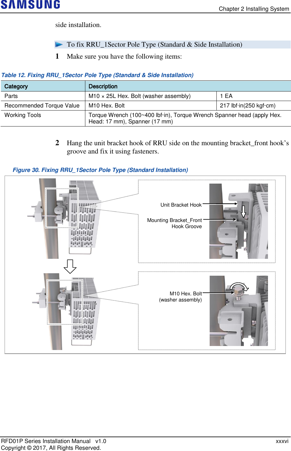
![Chapter 2 Installing System RFD01P Series Installation Manual v1.0 xxxiii Copyright © 2017, All Rights Reserved. 3 Locate the carriage bolt in the side open hole of the mounting bracket_rear and fix the fastening materials on both sides. Figure 25. Fixing Mounting Bracket Assembly_1Sector Pole Type (2) 4 Check the level of mounting bracket assembly on a pole and adjust the level. Figure 26. Leveling Mounting Bracket Assembly_ 1Sector Pole Type When fixing the pole mounting bracket assembly on a pole, be sure to check the level of bracket. After finishing the installation, you can adjust the level minutely. When occurring poor leveling, adjust the position of fasteners used to fix the Mounting bracket assembly or its leveling status. If it is level, the bubble of the spirit level is positioned at the center of both lines. [1Sector Side & Standard Mounting Bracket Assembly] Mounting Bracket_Rear Side Hole M10 Carriage Bolt](https://usermanual.wiki/Samsung-Electronics-Co/RFD01P-13A.User-Manual-2-Installation/User-Guide-3423645-Page-47.png)
![Chapter 2 Installing System RFD01P Series Installation Manual v1.0 xxxv Copyright © 2017, All Rights Reserved. 3 Locate the carriage bolt in the side open hole of the mounting bracket_rear and fix the fastening materials on both sides. Figure 28. Fixing Mounting Bracket Assembly_3Sector Pole Type (2) 4 Check the level of mounting bracket assembly on a pole and adjust the level. Figure 29. Leveling Mounting Bracket Assembly_ 3Sector Pole Type When fixing the pole mounting bracket assembly on a pole, be sure to check the level of bracket. After finishing the installation, you can adjust the level minutely. When occurring poor leveling, adjust the position of fasteners used to fix the Mounting bracket assembly or its leveling status. Fixing RRU For 1 Sector The method for installing the 1sector RRU is sorted into standard installation and [3Sector Side Mounting Bracket Assembly] If it is level, the bubble of the spirit level is positioned at the center of both lines. Side Hole M10 Carriage Bolt Mounting Bracket_Rear](https://usermanual.wiki/Samsung-Electronics-Co/RFD01P-13A.User-Manual-2-Installation/User-Guide-3423645-Page-49.png)
![Chapter 2 Installing System RFD01P Series Installation Manual v1.0 xxxviii Copyright © 2017, All Rights Reserved. For 3 Sector 3sector RRU can be installed by only side installation. To fix RRU_3Sector Pole Type 1 Make sure you have the following items: Table 13. Parts and Tools for fixing RRU_3Sector Pole Type Category Description Parts M10 × 25L Hex. Bolt (washer assembly) 3 EA Recommended Torque Value M10 Hex. Bolt 217 lbfin(250 kgf·cm) Working Tools Torque Wrench (100~400 lbf·in), Torque Wrench Spanner head (apply Hex. Head: 17 mm), Spanner (17 mm) Check the location to install the RRU. Fix the RRU according to the order of [RRU-0 RRU-1 RRU-2]. RRU-0 RRU-1 RRU-2 RRU-0 RRU-1 RRU-2](https://usermanual.wiki/Samsung-Electronics-Co/RFD01P-13A.User-Manual-2-Installation/User-Guide-3423645-Page-52.png)
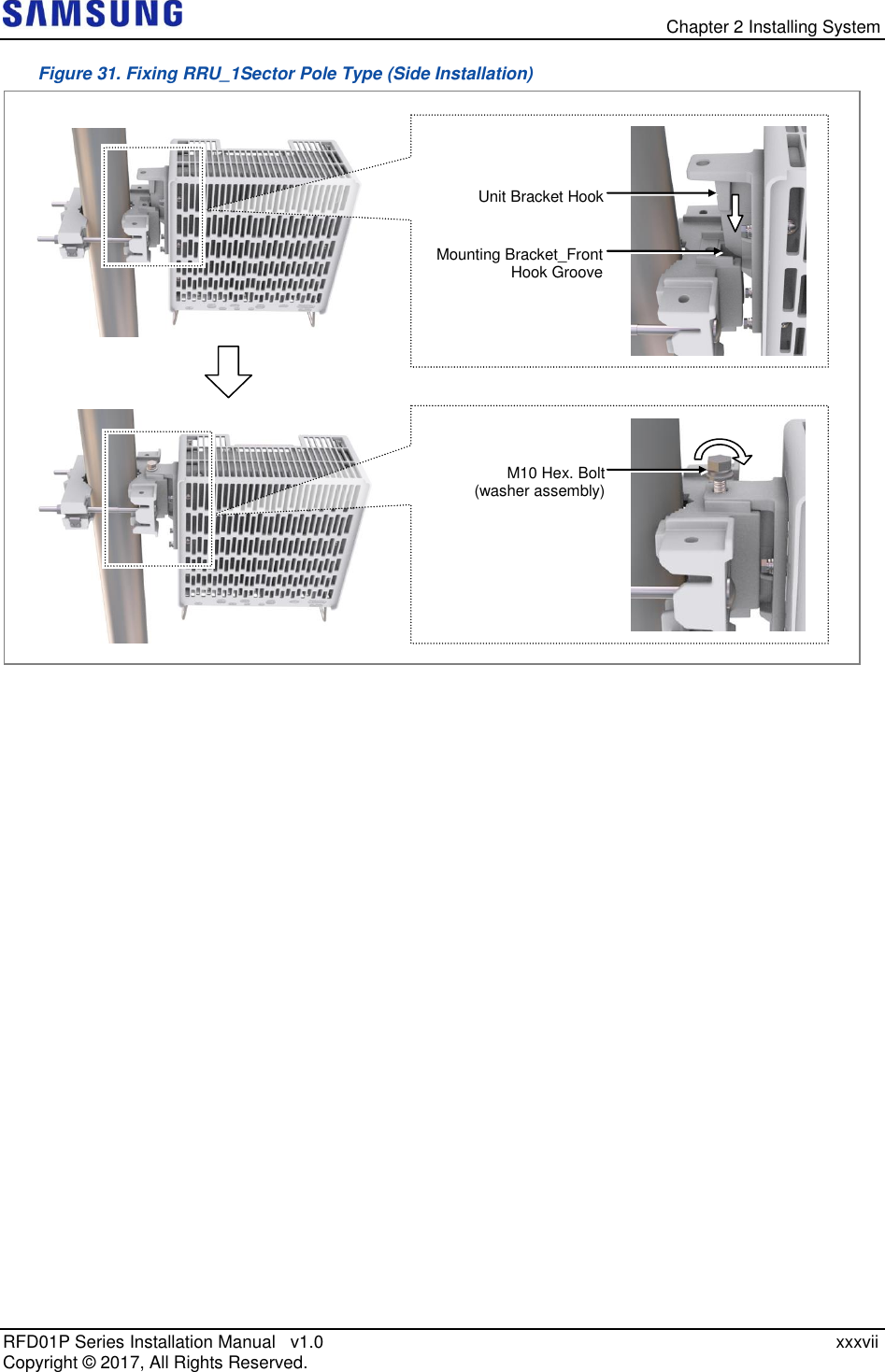
![Chapter 2 Installing System RFD01P Series Installation Manual v1.0 xxxix Copyright © 2017, All Rights Reserved. 2 Hang the unit bracket hook of RRU_0 side on the mounting bracket_front hook’s groove and fix it using fasteners. Figure 32. Fixing RRU_3 Sector Pole Type (1) 3 Fix RRU-1 and RRU-2 in the same way as the RRU_0. Figure 33. Fixing RRU_3 Sector Pole Type (2) [RRU-0] [RRU-0] [RRU-1] [RRU-0] [RRU-1] [RRU-2] [RRU-0] Unit Bracket Hook Mounting Bracket_Front Hook Groove M10 Hex. Bolt (washer assembly) [RRU-0]](https://usermanual.wiki/Samsung-Electronics-Co/RFD01P-13A.User-Manual-2-Installation/User-Guide-3423645-Page-53.png)
![Chapter 2 Installing System RFD01P Series Installation Manual v1.0 xli Copyright © 2017, All Rights Reserved. 2 Check the distance between the location for fixing the RRU and anchor bolt hole. Figure 34. RRU marking dimensions_1Sector Wall Type [Rear View] [Side Installation] [Standard Installation] Unit: in. (mm) [Side View] 3.48 (88.5) 5.11 (130) 13.38 (340) 4.13 (105) 4.13 (105) 15.47 (393) 5.11 (130) 6.61 (168) 0.74 (19) 0.82 (21) 3.48 (88.5) 15.47 (393) : Anchor Bolt Hole](https://usermanual.wiki/Samsung-Electronics-Co/RFD01P-13A.User-Manual-2-Installation/User-Guide-3423645-Page-55.png)
![Chapter 2 Installing System RFD01P Series Installation Manual v1.0 xlii Copyright © 2017, All Rights Reserved. Figure 35. RRU marking dimensions_3Sector Wall Type [Rear View] [Side Installation] [Standard Installation] [Side View] 5.11 (130) 20 (508) 7.48 (190) 3.48 (88.5) 15.47 (393) 5.11 (130) 13.38 (340) 4.13 (105) 4.13 (105) 5.11 (130) 13.38 (340) 4.13 (105) 4.13 (105) 3.48 (88.5) 5.11 (130) 13.38 (340) 4.13 (105) 4.13 (105) 15.47 (393) ≥55.9 (1420) ≥8 (200) ≥8 (200) 7.4 (188) Unit: in. (mm) : Anchor Bolt Hole](https://usermanual.wiki/Samsung-Electronics-Co/RFD01P-13A.User-Manual-2-Installation/User-Guide-3423645-Page-56.png)
![Chapter 2 Installing System RFD01P Series Installation Manual v1.0 xliii Copyright © 2017, All Rights Reserved. 3 Place a mounting bracket on the fixing location, Check the level status using a level and adjust the level of bracket assembly. 4 If the level status is normal, mark the anchor bolt holes on a wall. Figure 36. Marking_Wall Type If it is level, the bubble of the spirit level is positioned at the center of both lines. [3Sector Side Installation Mounting Bracket Assembly] [1Sector Side & Standard Mounting Bracket Assembly] 5.11 (130) [3Sector Standard Installation Mounting Bracket Assembly] ≥ 16.14 (410) ≥ 16.14 (410) Unit: in. (mm) / : Marking Point](https://usermanual.wiki/Samsung-Electronics-Co/RFD01P-13A.User-Manual-2-Installation/User-Guide-3423645-Page-57.png)
![Chapter 2 Installing System RFD01P Series Installation Manual v1.0 xliv Copyright © 2017, All Rights Reserved. To drill anchor holes and fix anchors 1 Make sure you have the following items: Table 15. Parts and Tools for Drilling & Anchoring Category Description Parts M10 Strong Anchor 2 EA Woking Tools Hammer Drill, Concrete Drill Bit [0.55 in. (14 mm)], Vacuum Cleaner, Hammer, Anchor Punch (For M10 Strong Anchor) Table 16. Anchor Bolt Drill Bits and Hole Depth Category Anchor Bolt Drill Bits Hole Depth RRU (Wall Type) M10 0.55 in. (14 mm) 1.73 in. (44 mm) 2 Drill anchor holes at marked points with removing dust from the holes using a cleaner. Fix strong anchor to the drilled hole. Figure 37. Drilling & Anchoring Hammer Drill Vacuum Cleaner 0.55 in. (14 mm) M10 Strong Anchor Anchor Punch Hammer [O] * Remove the debris from the drilled hole. [Anchor Hole Cross Section] 1.73 in. (44 mm) [X] 0.55 in. (14 mm)](https://usermanual.wiki/Samsung-Electronics-Co/RFD01P-13A.User-Manual-2-Installation/User-Guide-3423645-Page-58.png)
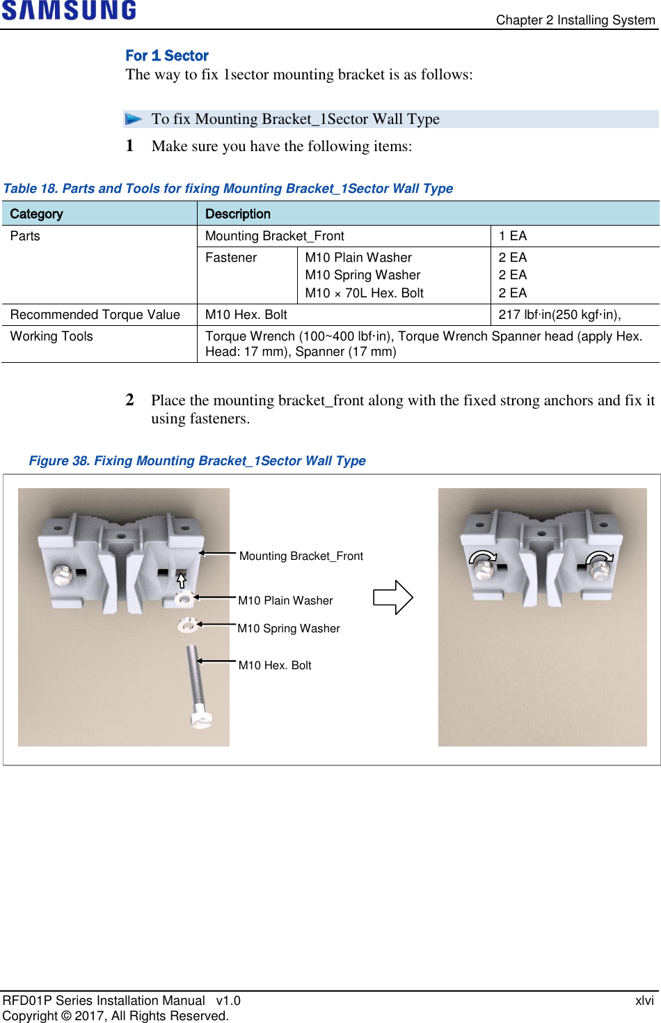
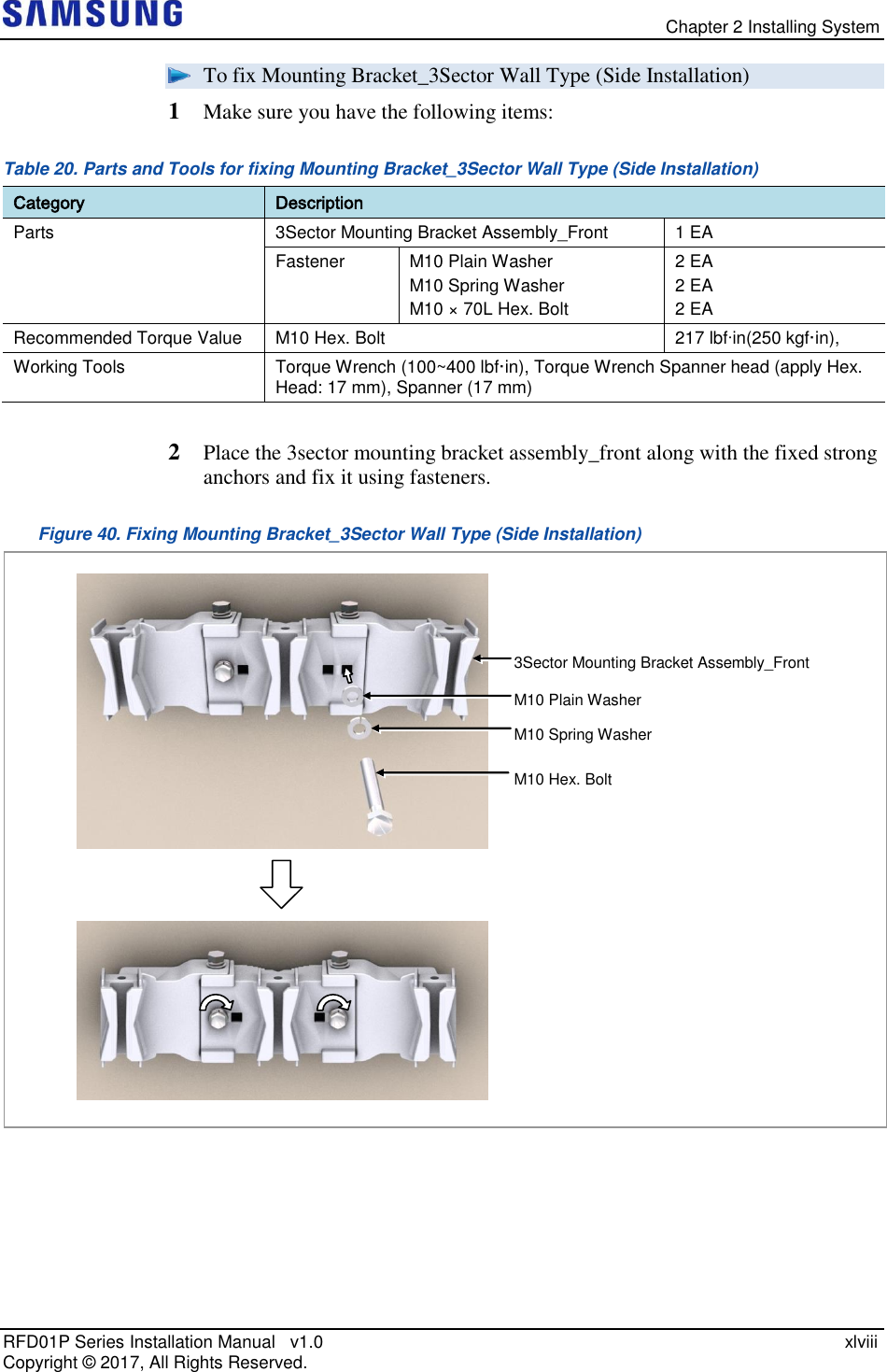
![Chapter 2 Installing System RFD01P Series Installation Manual v1.0 xlv Copyright © 2017, All Rights Reserved. Fixing Mounting Bracket Check the Mounting Bracket_front type per installation type and sector type before installing the Mounting bracket. Table 17. Mounting Bracket type per installation type and sector type_Wall Type Sector Type Installation Type Bracket Type Unit 1Sector Standard Installation Mounting Bracket_Front 1 EA 3Sector Mounting Bracket_Front 3 EA 1Sector Side Installation Mounting Bracket_Front 1 EA 3Sector 3Sector Mounting Bracket Assembly_Front 1 EA When fixing the mounting bracket_front or 3sector mounting bracket assembly_front on a wall, ‘A’ side should stick on the wall. [Top View] A Wall Mounting Bracket_Front A A A Wall 3Sector Mounting Bracket Assembly_Front [Top View] [Mounting Bracket_Front] [3Sector Mounting Bracket Assembly_Front]](https://usermanual.wiki/Samsung-Electronics-Co/RFD01P-13A.User-Manual-2-Installation/User-Guide-3423645-Page-59.png)
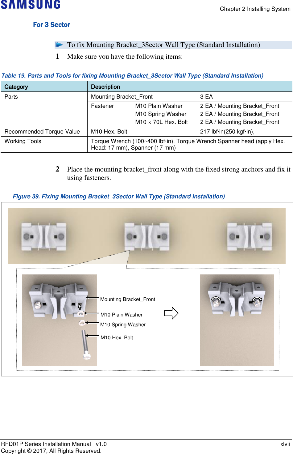
![Chapter 2 Installing System RFD01P Series Installation Manual v1.0 li Copyright © 2017, All Rights Reserved. For 3 Sector The method for installing the 3sector RRU is sorted into standard installation and side installation. To fix RRU_3Sector Pole Type (Standard Installation) 1 Make sure you have the following items: Table 22. Parts and Tools for fixing RRU_3Sector Wall Type (Standard Installation) Category Description Parts M10 × 25L Hex. Bolt (washer assembly) 3 EA Recommended Torque Value M10 Hex. Bolt 217 lbfin(250 kgf·in), Working Tools Torque Wrench (100~400 lbf·in), Torque Wrench Spanner head (apply Hex. Head: 17 mm), Spanner (17 mm) Check the location to install the RRU. Fix the RRU according to the order of [RRU-0 RRU-1 RRU-2]. RRU-1 RRU-0 RRU-2 RRU-1 RRU-0 RRU-2](https://usermanual.wiki/Samsung-Electronics-Co/RFD01P-13A.User-Manual-2-Installation/User-Guide-3423645-Page-65.png)
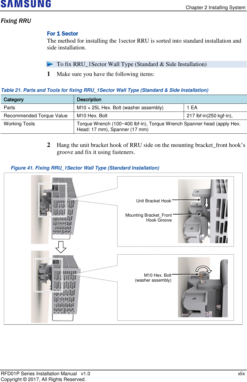
![Chapter 2 Installing System RFD01P Series Installation Manual v1.0 lii Copyright © 2017, All Rights Reserved. 2 Hang the unit bracket hook of RRU_0 side on the mounting bracket_front hook’s groove and fix it using fasteners. Figure 43. Fixing RRU_3 Sector Wall Type (Standard Installation 1) 3 Fix RRU-1 and RRU-2 in the same way as the RRU_0. Figure 44. Fixing RRU_3 Sector Wall Type (Standard Installation 2) [RRU-0] [RRU-1] [RRU-2] Unit Bracket Hook Mounting Bracket_Front Hook Groove M10 Hex. Bolt (washer assembly) [RRU-0] [RRU-0]](https://usermanual.wiki/Samsung-Electronics-Co/RFD01P-13A.User-Manual-2-Installation/User-Guide-3423645-Page-66.png)
![Chapter 2 Installing System RFD01P Series Installation Manual v1.0 liii Copyright © 2017, All Rights Reserved. To fix RRU_3Sector Pole Type (Side Installation) 1 Make sure you have the following items: Table 23. Parts and Tools for fixing RRU_3Sector Wall Type (Side Installation) Category Description Parts M10 × 25L Hex. Bolt (washer assembly) 3 EA Recommended Torque Value M10 Hex. Bolt 217 lbfin(250 kgf·in), Working Tools Torque Wrench (100~400 lbf·in), Torque Wrench Spanner head (apply Hex. Head: 17 mm), Spanner (17 mm) Check the location to install the RRU. Fix the RRU according to the order of [RRU-0 RRU-1 RRU-2]. RRU-1 RRU-0 RRU-2 RRU-1 RRU-0 RRU-2](https://usermanual.wiki/Samsung-Electronics-Co/RFD01P-13A.User-Manual-2-Installation/User-Guide-3423645-Page-67.png)
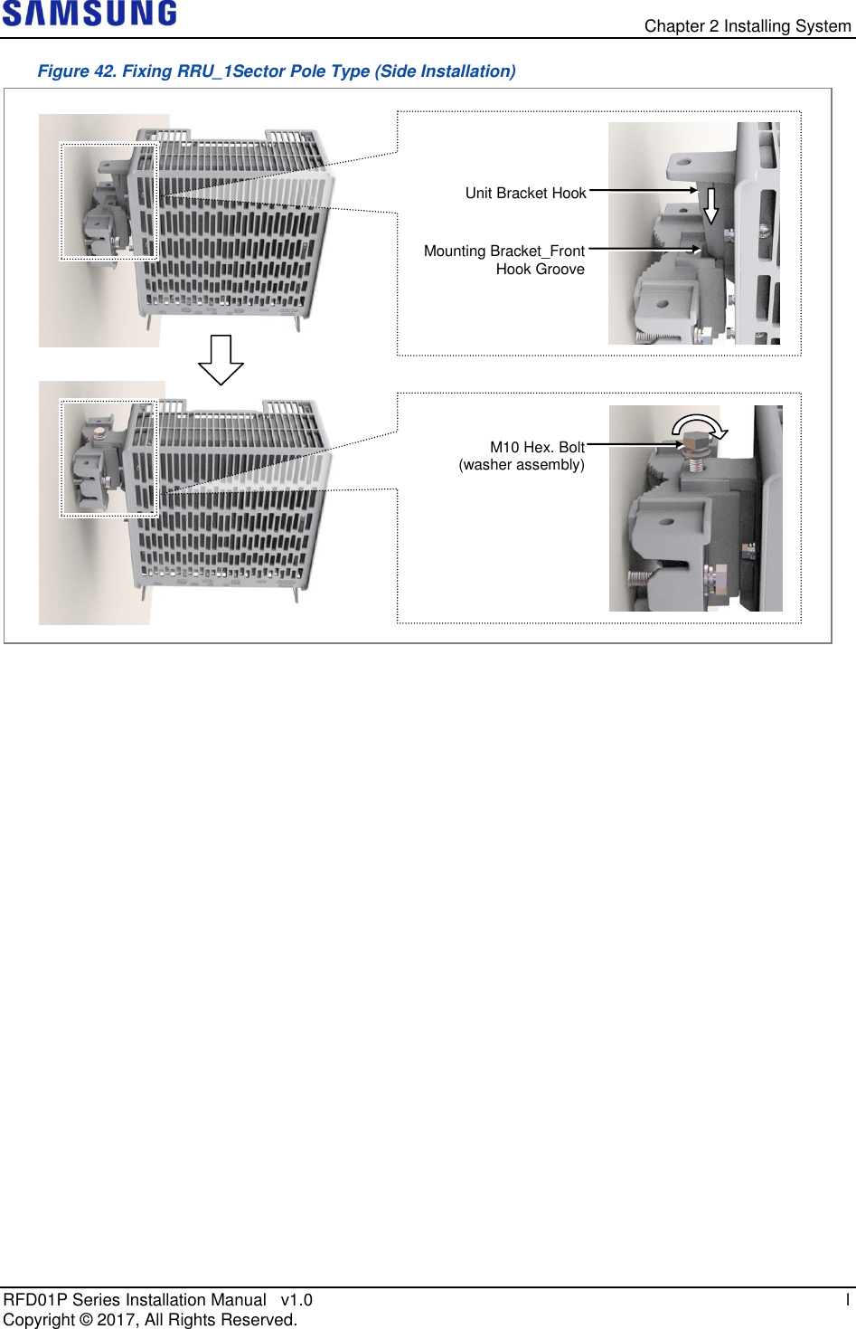
![Chapter 2 Installing System RFD01P Series Installation Manual v1.0 liv Copyright © 2017, All Rights Reserved. 2 Hang the unit bracket hook of RRU_0 side on the mounting bracket_front hook’s groove and fix it using fasteners. Figure 45. Fixing RRU_3 Sector Wall Type (Side Installation 1) 3 Fix RRU-1 and RRU-2 in the same way as the RRU_0. Figure 46. Fixing RRU_3 Sector Wall Type (Side Installation 2) [RRU-0] [RRU-0] [RRU-1] [RRU-0] [RRU-1] [RRU-2] [RRU-0] Unit Bracket Hook Mounting Bracket_Front Hook Groove M10 Hex. Bolt (washer assembly) [RRU-0]](https://usermanual.wiki/Samsung-Electronics-Co/RFD01P-13A.User-Manual-2-Installation/User-Guide-3423645-Page-68.png)
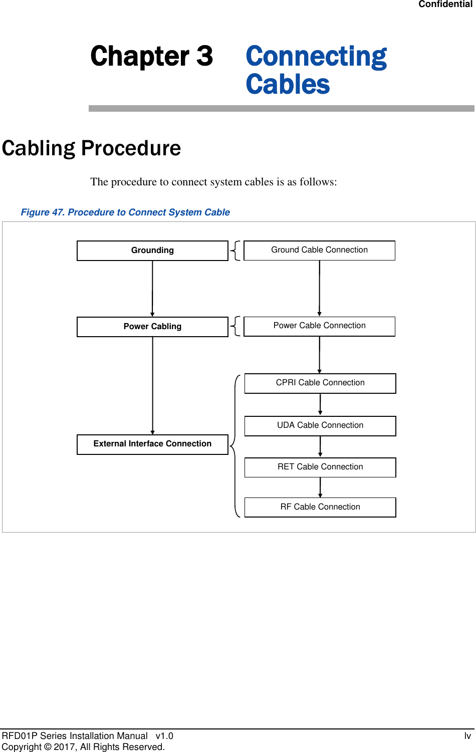
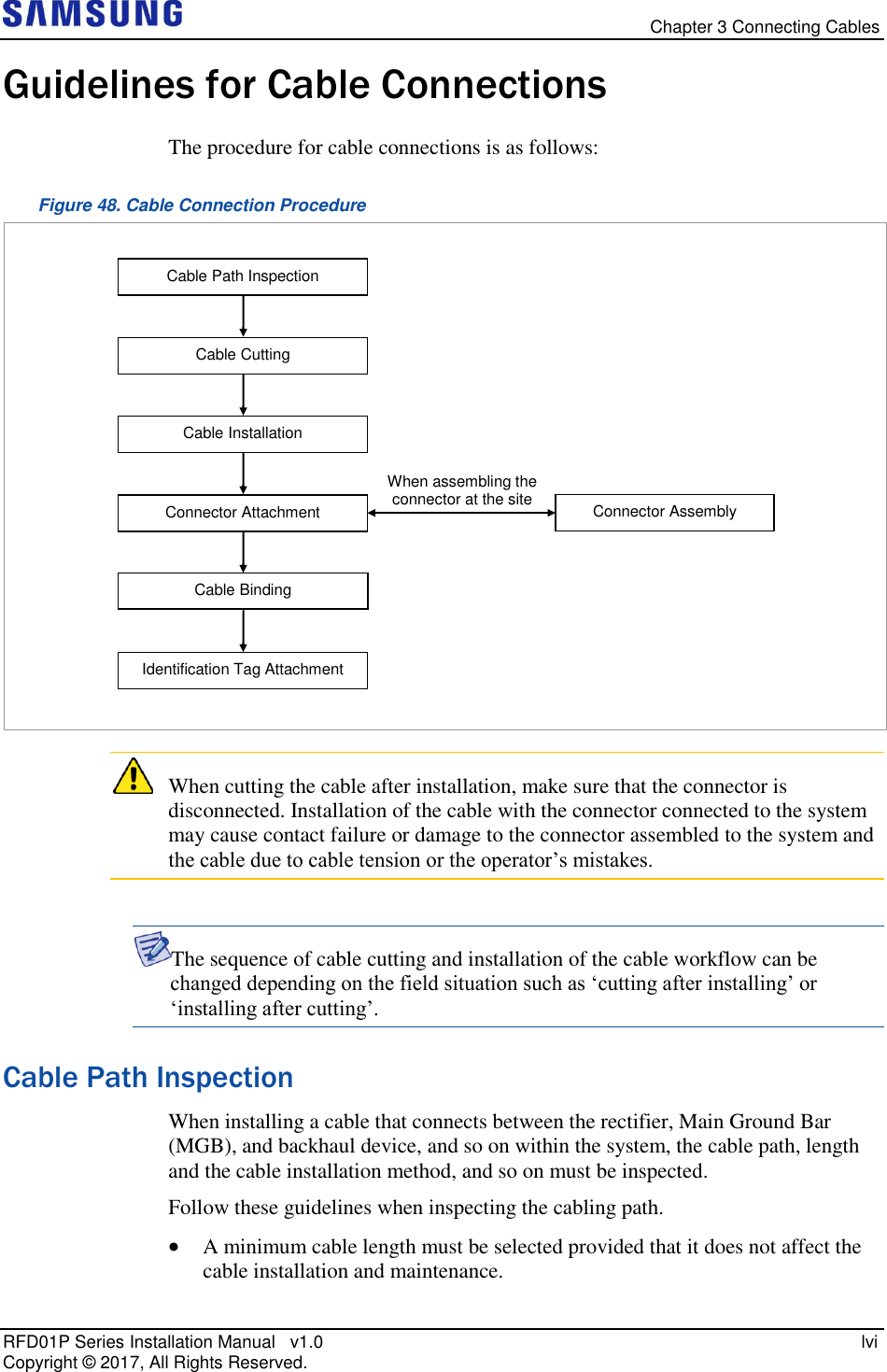
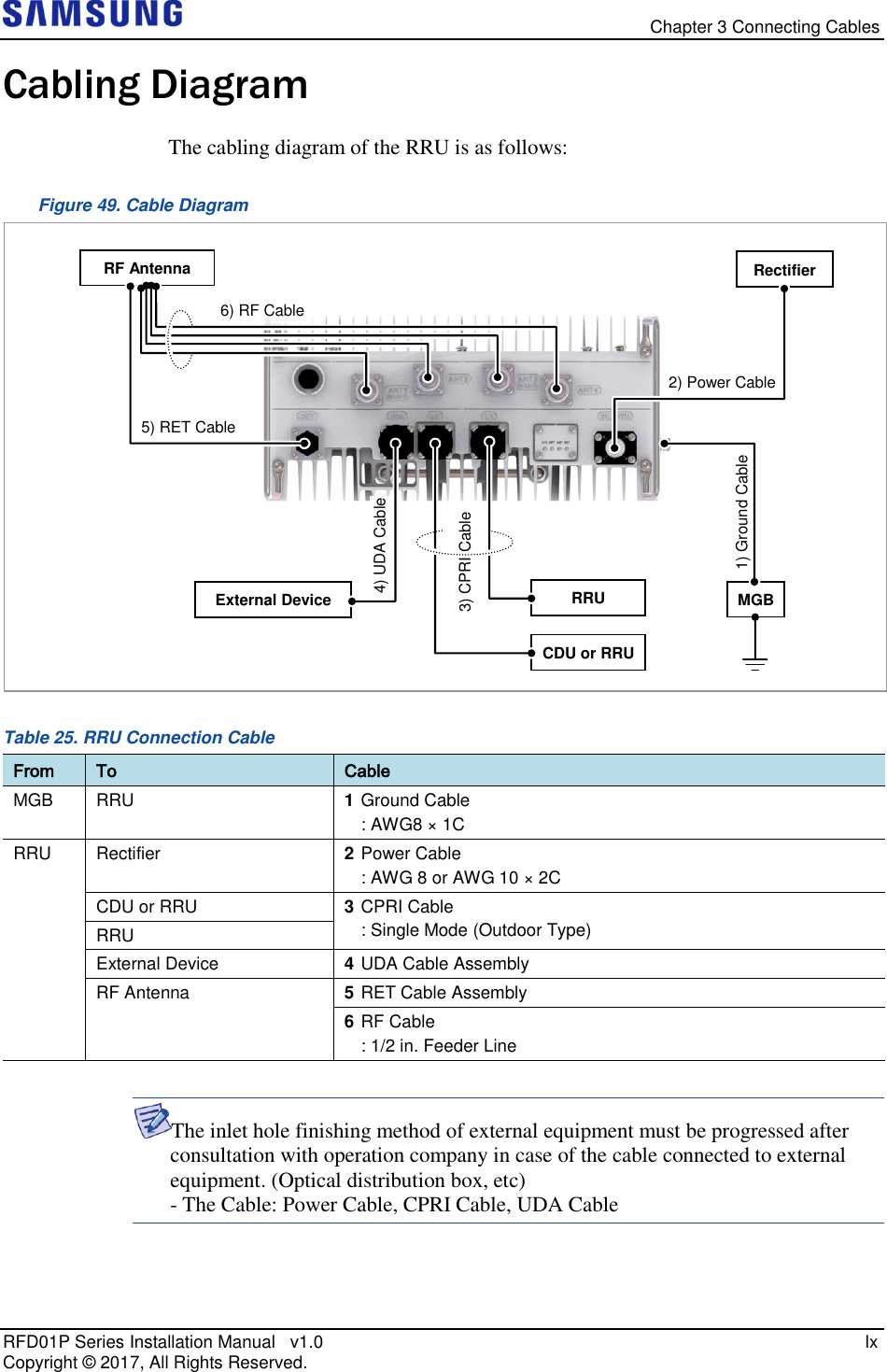
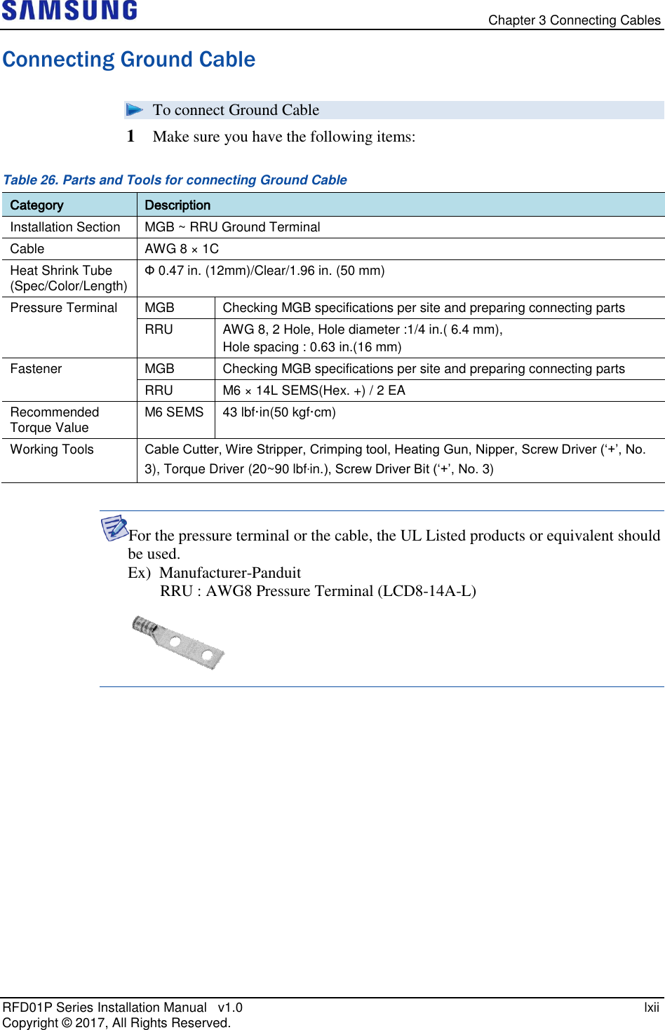
![Chapter 3 Connecting Cables RFD01P Series Installation Manual v1.0 lxiii Copyright © 2017, All Rights Reserved. 2 Install a ground cable from the MGB to the RRU ground terminal. Figure 50. Connecting Ground Cable (1) 3 Assemble a pressure terminal and a heat shrink tube at the end of the RRU ground cable. 4 Align the pressure terminal to the mounting hole of the RRU ground terminal. 5 Firmly fix the pressure terminal onto the RRU ground terminal using fasteners. Figure 51. Connecting Ground Cable (2) Ground Cable Heat Shrink Tube (Clear) Pressure Terminal M6 SEMS (Hex. +) [Bottom View] MGB Ground Cable Front](https://usermanual.wiki/Samsung-Electronics-Co/RFD01P-13A.User-Manual-2-Installation/User-Guide-3423645-Page-77.png)
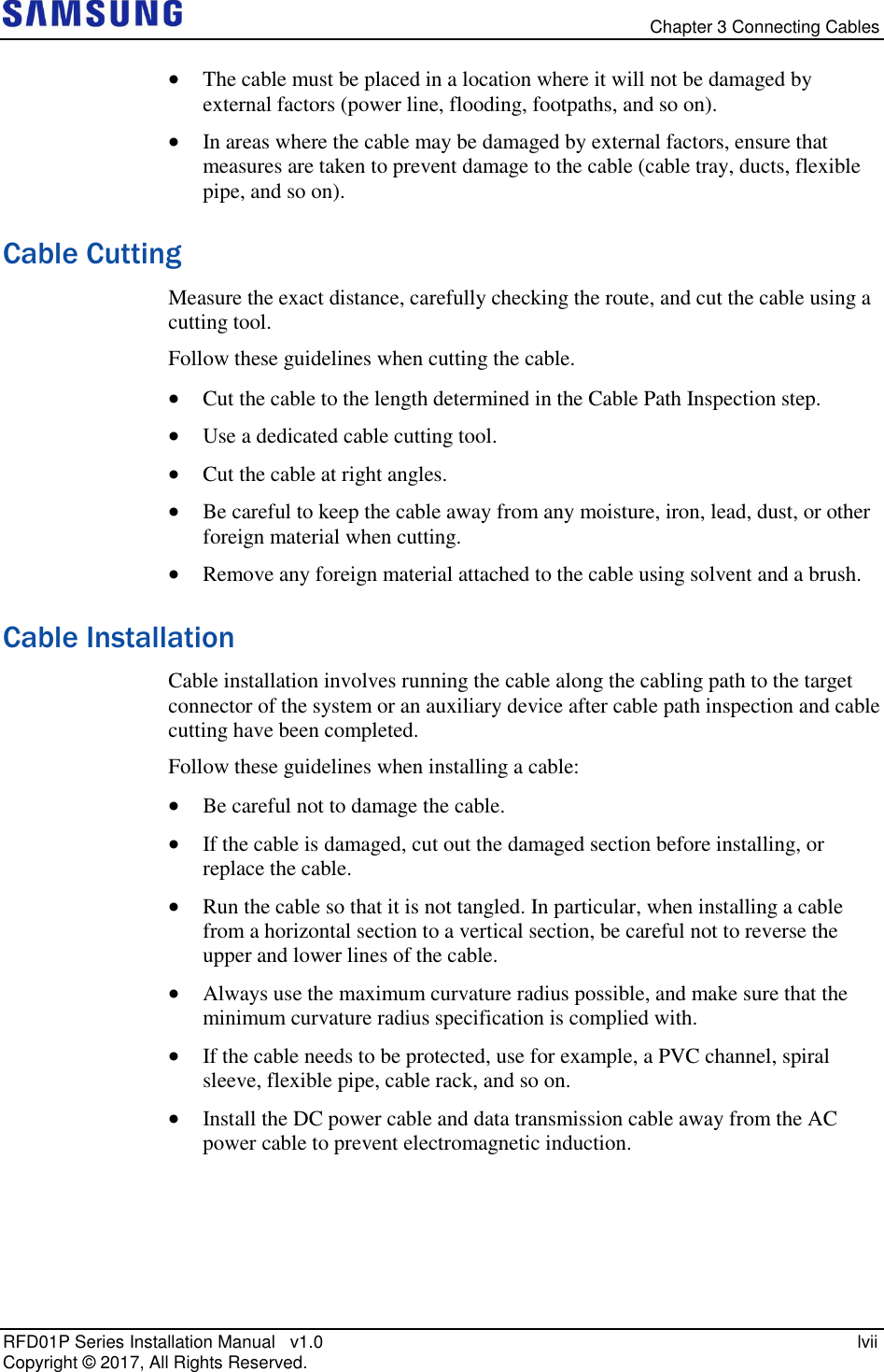
![Chapter 3 Connecting Cables RFD01P Series Installation Manual v1.0 lxv Copyright © 2017, All Rights Reserved. Connecting Power Cable To connect Power cable 1 Make sure you have the following items: Table 27. Parts and Tools for connecting Power Cable Category Description Installation Section Rectifier ~ RRU Power Input Port Cable AWG 8 or AWG 10 × 2C (The color of the core wire can be changed according to the specification of the cable used.) Connector Rectifier Check specifications of rectifier output terminal per site and prepare fasteners. RRU JONHON, Push Pull Type, CT48J-1502TSCBM-07 to open Working Tools Cable Cutter, Wire Stripper, Compressor, Heating Gun, Nipper Table 28. Power Cable/Connector Pin Map Power Connector Pin No. Description Color Pin 1 -48 V DC The color of the core wire can be changed according to the specification of the cable used. Pin 2 RTN [Cable side Connector] [System side Connector] Bump Groove Bump Groove Pin 1 Pin 2 Pin 1 Pin 2](https://usermanual.wiki/Samsung-Electronics-Co/RFD01P-13A.User-Manual-2-Installation/User-Guide-3423645-Page-79.png)
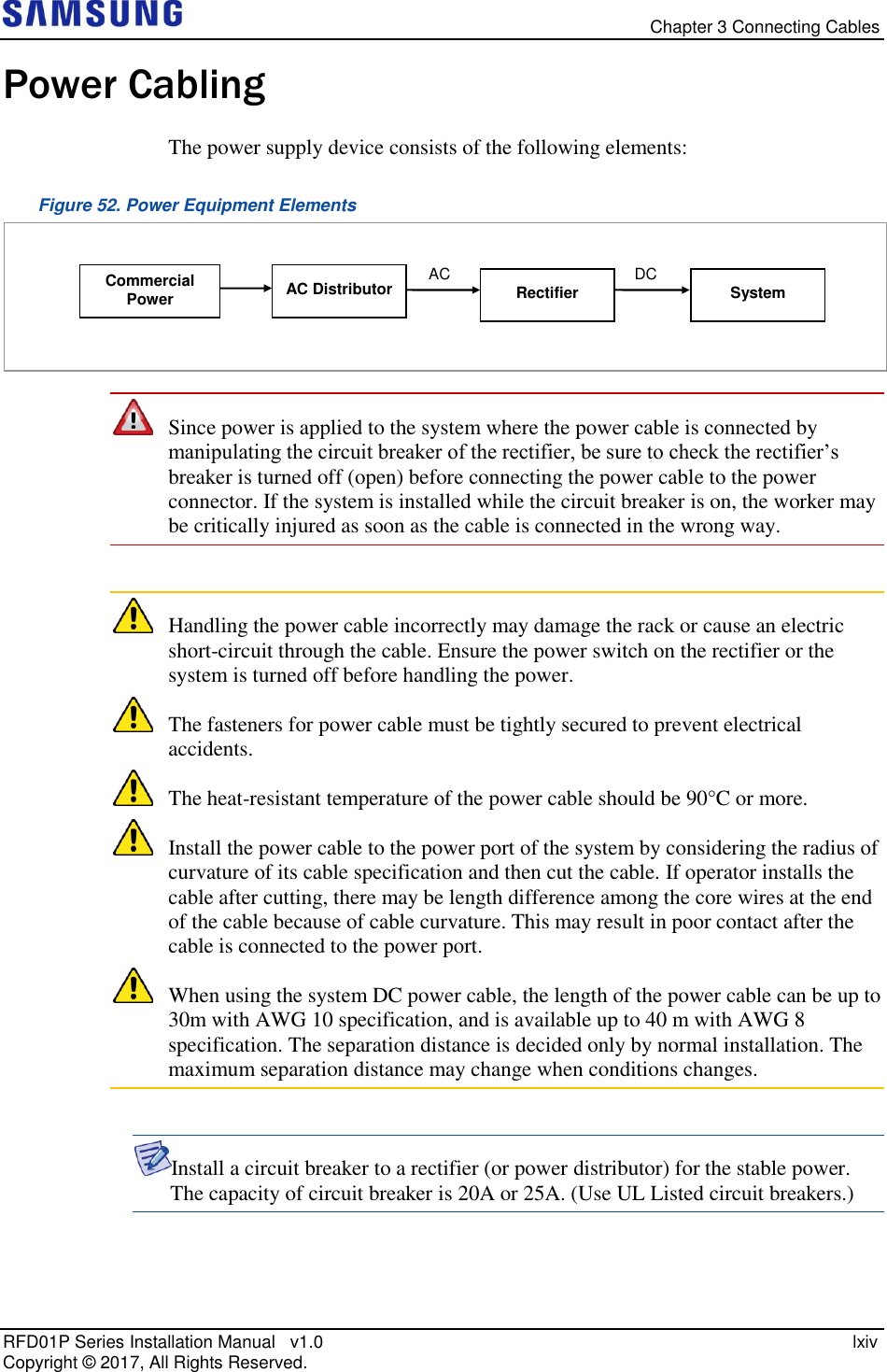
![Chapter 3 Connecting Cables RFD01P Series Installation Manual v1.0 lxvi Copyright © 2017, All Rights Reserved. 2 Install a DC power cable from the rectifier to the RRU. Figure 53. Connecting Power Cable (1) 3 Insert the connector aligning the cable side connector’s white dot and system side connector’s white dot. When inserting the connector, push the shell to upper side. Figure 54. Connecting Power Cable (2) System side connector’s white dot Cable side connector’s white dot Shell Push [Bottom View] Rectifier Power Cable Front](https://usermanual.wiki/Samsung-Electronics-Co/RFD01P-13A.User-Manual-2-Installation/User-Guide-3423645-Page-80.png)
![Chapter 3 Connecting Cables RFD01P Series Installation Manual v1.0 lxvii Copyright © 2017, All Rights Reserved. When the connector is fastened tight, the white line on the system side connector should be invisible (or hidden). The method for connecting/disconnecting the power connector is as follows: - For connecting the connector, push the shell to upper side. - For disconnecting the connector, pull the coupling nut to lower side. Shell Coupling Nut Push Pull White Line [White Line is invisible] [White Line is visible]](https://usermanual.wiki/Samsung-Electronics-Co/RFD01P-13A.User-Manual-2-Installation/User-Guide-3423645-Page-81.png)
![Chapter 3 Connecting Cables RFD01P Series Installation Manual v1.0 lxviii Copyright © 2017, All Rights Reserved. Interface Cable Connection Remove/Insert Optical Module If the optical module needs to be removed or inserted before connecting the cable, follow the below process. To remove Optical Module 1 Hang the Optic Transceiver Removal Tool’s hook on the optical module’s bail within the system. Figure 55. Optical Module Removal (1) 2 Completely remove the optical module from the transceiver by pulling the Optic Transceiver Removal Tool. Figure 56. Optical Module Removal (2) 3 Remove the optical module and the jig by pressing the Optic Transceiver Removal Tool’s hook grip. Figure 57. Optical Module Removal (3) Optic Transceiver Removal Tool Optical Module Transceiver Optical Connector Optical Module [System Inside] Optic Transceiver Removal Tool’s Hook Bail [Front View] Location to hang the Optic Transceiver Removal Tool](https://usermanual.wiki/Samsung-Electronics-Co/RFD01P-13A.User-Manual-2-Installation/User-Guide-3423645-Page-82.png)
![Chapter 3 Connecting Cables RFD01P Series Installation Manual v1.0 lxix Copyright © 2017, All Rights Reserved. To inset Optical Module Push the optical module into the transceiver within the connector. Figure 58. Optical Module Inset Inset the optical module's bail, facing the front of the system, to the port. Do not inset when the optic module's bail is unlocked. Optical Module Bail [Raised: Lock] [Lowered: Unlock] Optical Module Bail [System Inside]Optic Transceiver Removal Tool Transceiver Optical Module Optical Connector](https://usermanual.wiki/Samsung-Electronics-Co/RFD01P-13A.User-Manual-2-Installation/User-Guide-3423645-Page-83.png)
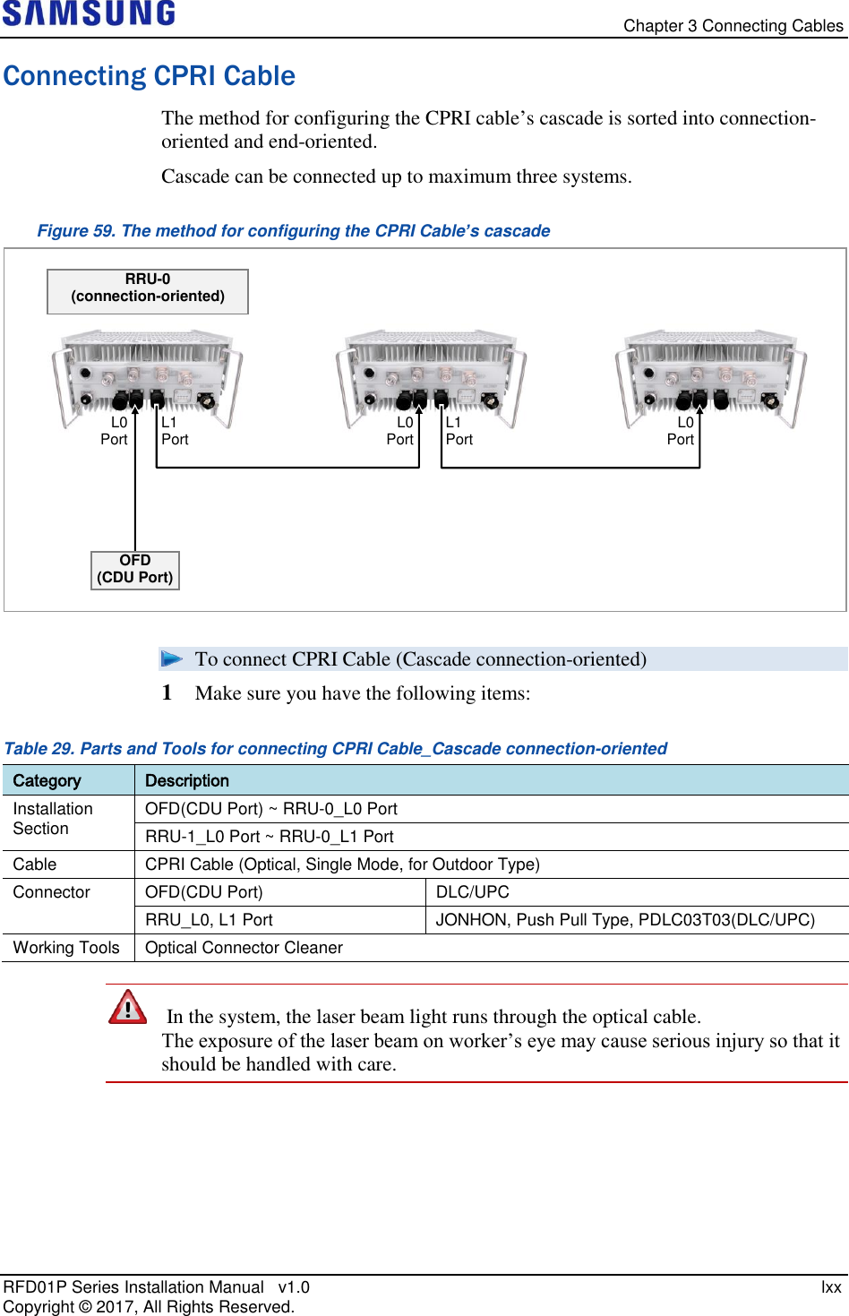
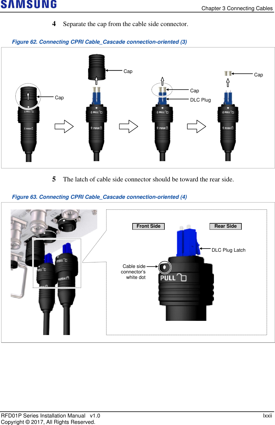
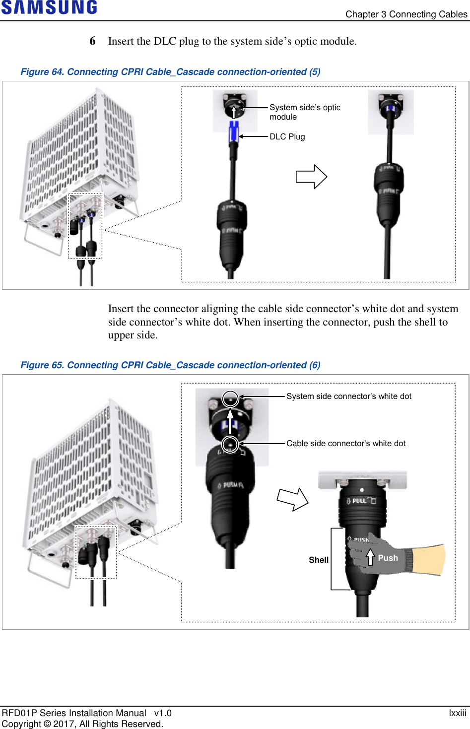
![Chapter 3 Connecting Cables RFD01P Series Installation Manual v1.0 lxxi Copyright © 2017, All Rights Reserved. Remove the cap of the optical connector before connecting. - Before connecting the optical cable, check if the ferrule of the connector is soiled. Be careful to keep the cutting section away from dust or foreign material. If the cable is soiled with foreign material, do not blow to remove them. - Make sure to clean the connector in accordance with the cleaning directions in Annex. - Do not touch the ferrule at the end of optical cable because it is easy to be damaged. 2 Install a CPRI cable from the OFD (CDU port) to the RRU. Figure 60. Connecting CPRI Cable_Cascade connection-oriented (1) 3 Separate the cap from the system side connector (L0, L1 port). Figure 61. Connecting CPRI Cable_Cascade connection-oriented (2) Cap L0 Port L0 Port L1 Port L1 Port [Bottom View] OFD (CDU Port) or RRU-0 (L1 Port) CPRI Cable Front RRU-1 (L0 Port) or RRU-2 (L0 Port) CPRI Cable L0 L1 Ferrule [Before Removing Cap] [After Removing Cap] Cap](https://usermanual.wiki/Samsung-Electronics-Co/RFD01P-13A.User-Manual-2-Installation/User-Guide-3423645-Page-85.png)
![Chapter 3 Connecting Cables RFD01P Series Installation Manual v1.0 lxxiv Copyright © 2017, All Rights Reserved. When the connector is fastened tight, the white line on the system side connector should be invisible (or hidden). The method for connecting/disconnecting the CPRI (optical) connector is as follows: - For connecting the connector, push the shell to upper side. - For disconnecting the connector, pull the coupling nut to lower side. Shell Coupling Nut Push Pull White Line [White Line is invisible] [White Line is visible]](https://usermanual.wiki/Samsung-Electronics-Co/RFD01P-13A.User-Manual-2-Installation/User-Guide-3423645-Page-88.png)
![Chapter 3 Connecting Cables RFD01P Series Installation Manual v1.0 lxxv Copyright © 2017, All Rights Reserved. To connect CPRI cable (Cascade end-oriented) 1 Make sure you have the following items: Table 30. Parts and Tools for connecting CPRI Cable_Cascade end-oriented Category Description Installation Section RRU-1 L1 Port ~ RRU-2 L0 Port Cable CPRI Cable (Optical, Single Mode, for Outdoor Type) Connector RRU JONHON, Push Pull Type, PDLC03T03(DLC/UPC) Working Tools Optical Connector Cleaner In the system, the laser beam light runs through the optical cable. The exposure of the laser beam on worker’s eye may cause serious injury so that it should be handled with care. Remove the cap of the optical connector before connecting. - Before connecting the optical cable, check if the ferrule of the connector is soiled. Be careful to keep the cutting section away from dust or foreign material. If the cable is soiled with foreign material, do not blow to remove them. - Make sure to clean the connector in accordance with the cleaning directions in Annex. - Do not touch the ferrule at the end of optical cable because it is easy to be damaged. Because L1 port is not used in Cascade end-oriented, assemble the cap at the L1 port to prevent foreign substances and do not remove the cap discretionally. [L0 Port] [L1 Port] Using Not Using Ferrule [Before Removing Cap] [After Removing Cap] Cap](https://usermanual.wiki/Samsung-Electronics-Co/RFD01P-13A.User-Manual-2-Installation/User-Guide-3423645-Page-89.png)
![Chapter 3 Connecting Cables RFD01P Series Installation Manual v1.0 lxxvi Copyright © 2017, All Rights Reserved. 2 Install a CPRI cable from the RRU-1(L1 port) to the RRU-2 (L0 port). Figure 66. Connecting CPRI Cable_Cascade end-oriented (1) 3 Because the method for connecting the cascade end-oriented CPRI cable is identical to connection-oriented, refer to the how to connect it. Figure 67. Connecting CPRI Cable_Cascade end-oriented (2) [Bottom View] RRU-1 (L1 Port) CPRI Cable Front](https://usermanual.wiki/Samsung-Electronics-Co/RFD01P-13A.User-Manual-2-Installation/User-Guide-3423645-Page-90.png)
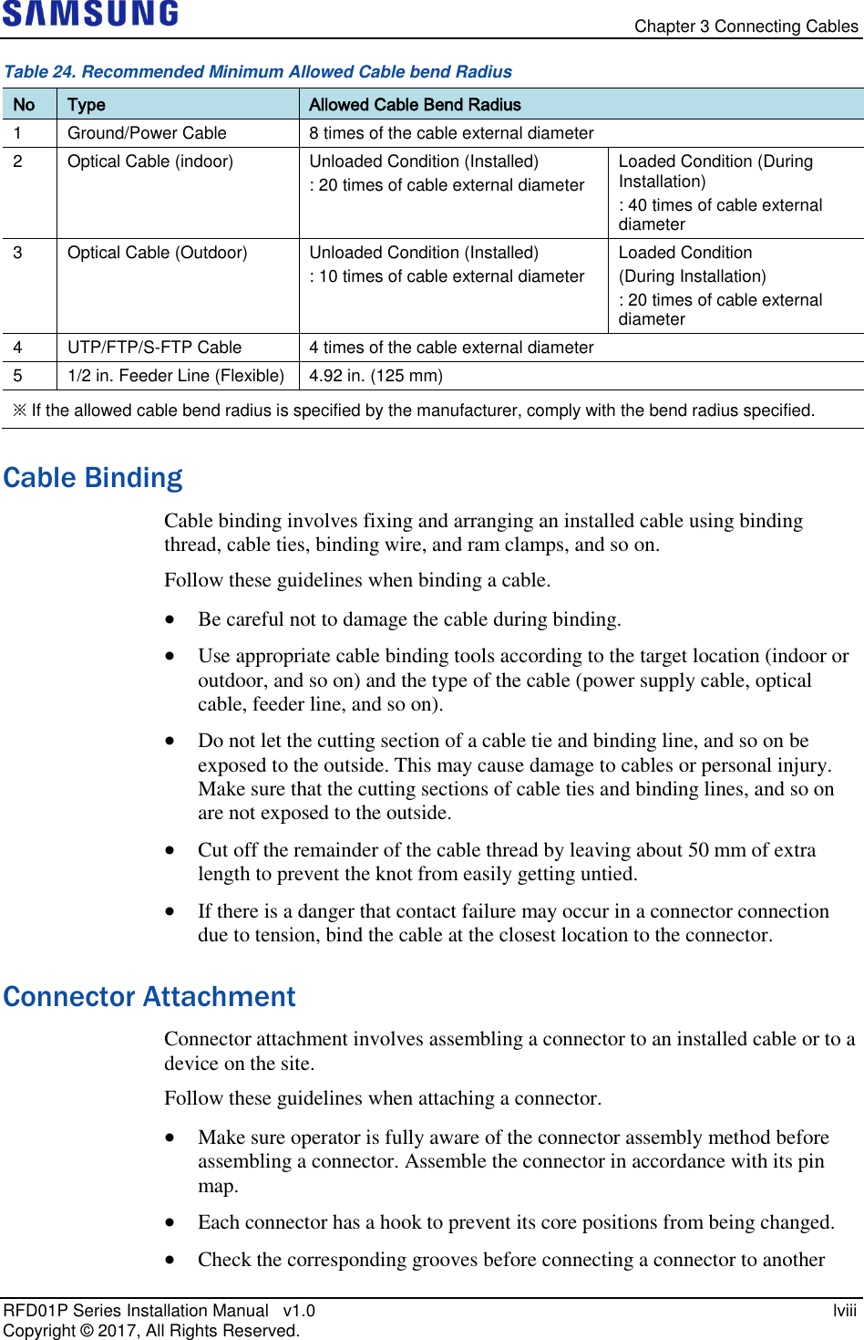
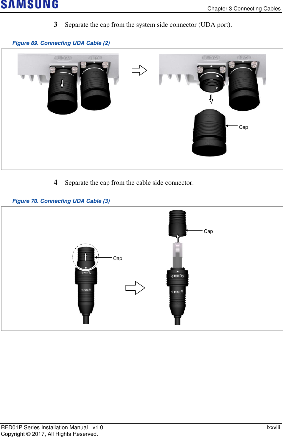
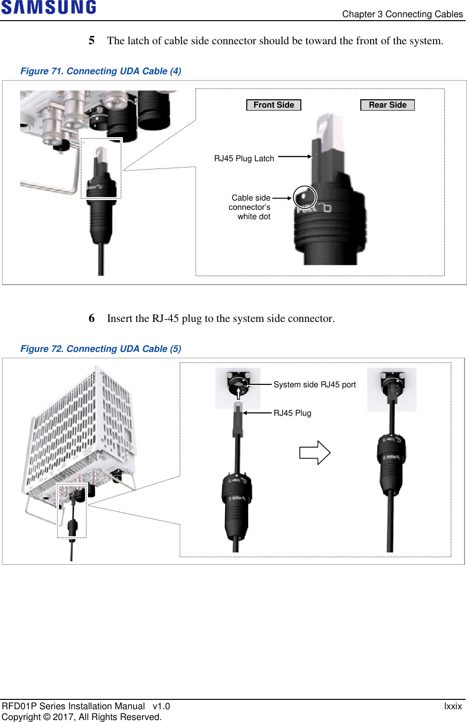
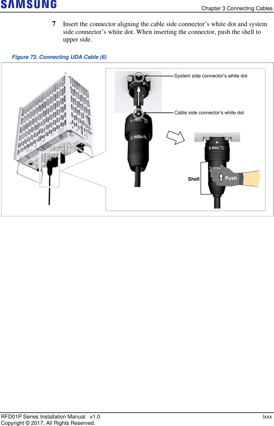
![Chapter 3 Connecting Cables RFD01P Series Installation Manual v1.0 lxxvii Copyright © 2017, All Rights Reserved. Connecting UDA Cable To connect UDA cable 1 Make sure you have the following items: Table 31. Parts and Tools for connecting UDA Cable Category Description Installation Section External Device ~ RRU UDA Port Cable UDA Cable Assembly (AWG24, 8C, CAT5e, SFTP) Connector External Device Check specifications of external device output terminal per site and prepare fasteners. RRU JONHON, Push Pull Type, RJ45MF-CT-07 Working Tool Cable Cutter, Wire Stripper, Nipper, LAN Tool Table 32. UDA Cable Pin Map System Side Color Map Rectifier Side Description 1 White/Orange 1 TX+ 2 Orange 2 TX- 3 White/Green 3 RX+ 4 Blue 4 - 5 White/Blue 5 - 6 Green 6 RX- 7 White/Brown 7 - 8 Brown 8 - Shell Shield Shell FGND 2 Install a UDA cable from the External Device to the RRU. Figure 68. Connecting UDA Cable (1) [Bottom View] External Device UDA Cable Front](https://usermanual.wiki/Samsung-Electronics-Co/RFD01P-13A.User-Manual-2-Installation/User-Guide-3423645-Page-91.png)
![Chapter 3 Connecting Cables RFD01P Series Installation Manual v1.0 lxxxi Copyright © 2017, All Rights Reserved. When the connector is fastened tight, the white line on the system side connector should be invisible (or hidden). The method for connecting/disconnecting the UDA(RJ45) connector is as follows: - For connecting the connector, push the shell to upper side. - For disconnecting the connector, pull the coupling nut to lower side. Shell Coupling Nut Push Pull White Line [White Line is invisible] [White Line is visible]](https://usermanual.wiki/Samsung-Electronics-Co/RFD01P-13A.User-Manual-2-Installation/User-Guide-3423645-Page-95.png)
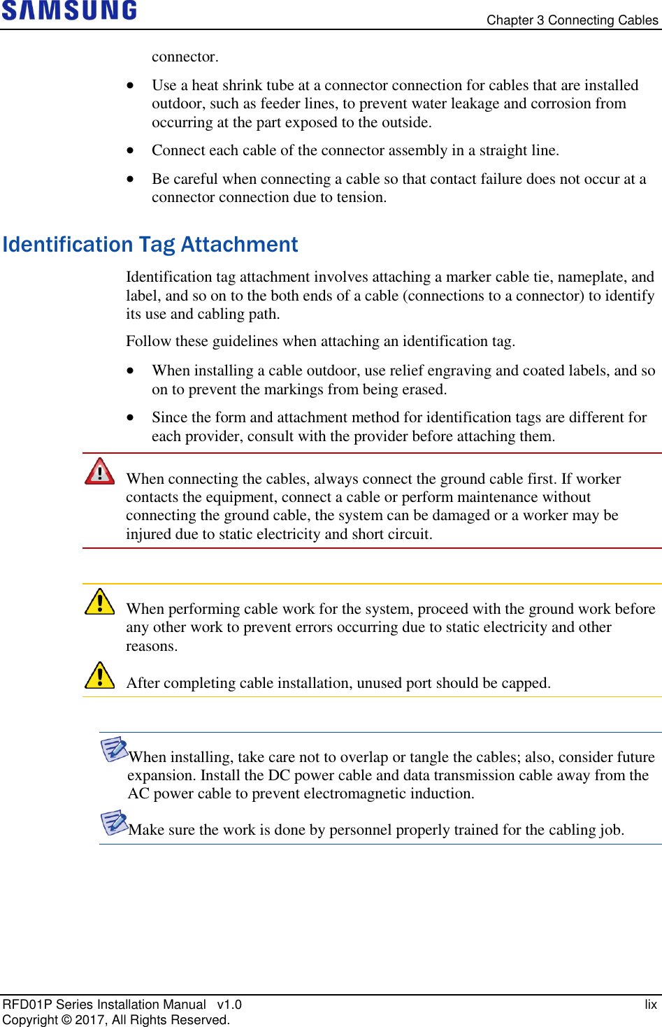
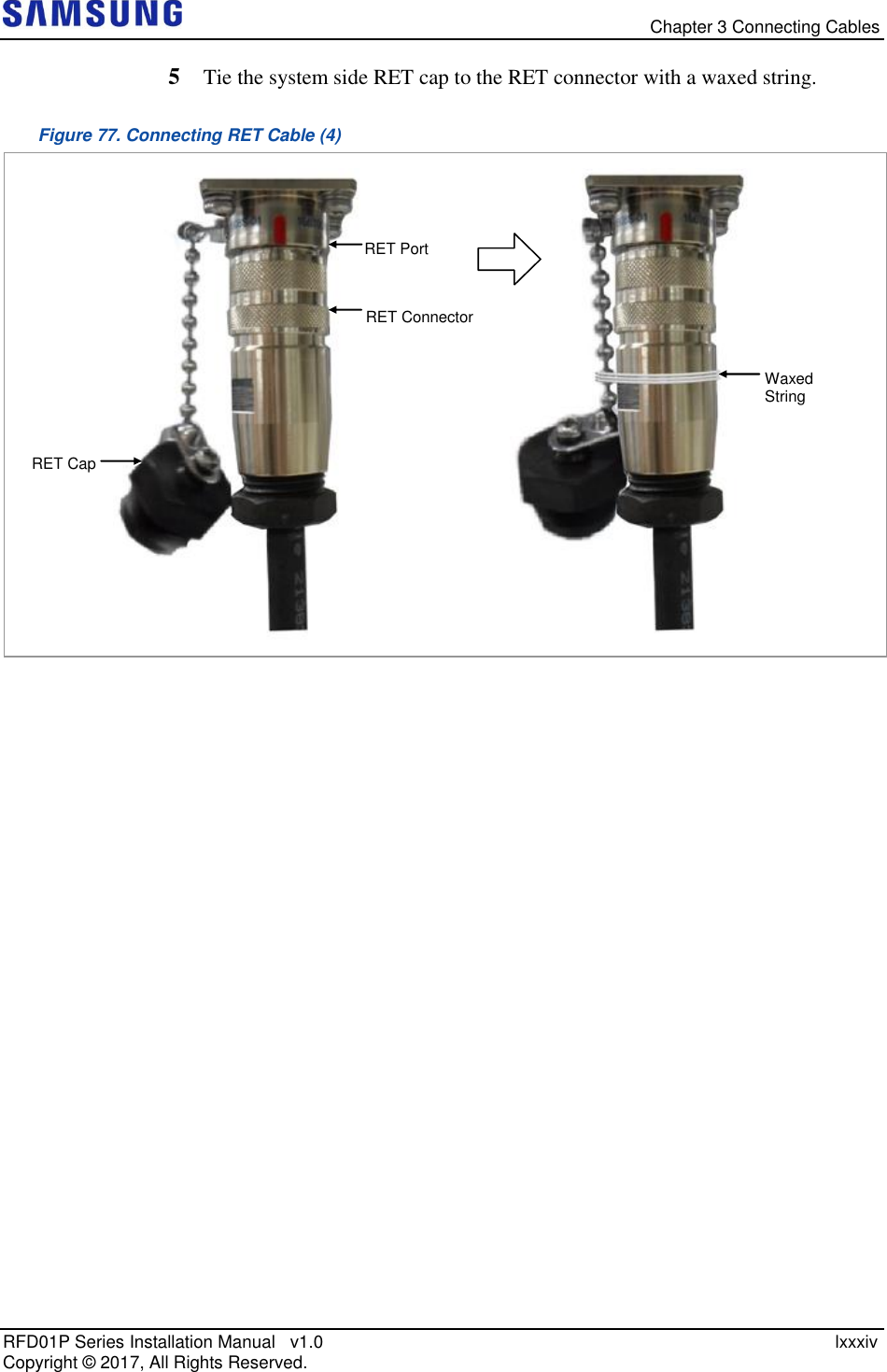
![Chapter 3 Connecting Cables RFD01P Series Installation Manual v1.0 lxxxii Copyright © 2017, All Rights Reserved. Connecting RET Cable To connect RET cable 1 Make sure you have the following items: Table 33. Parts for connecting RET Cable Category Description Installation Section RF Antenna ~ RRU RET port Cable RET Cable Assembly Connector RF Antenna Check the RF antenna (RETu) RET connector specification per site RRU AISG 2.0 Table 34. RET Cable Pin Map Pin No Description Cable Color 1 N/C (Not Connected) - 2 N/C (Not Connected) - 3 RS485 B White 4 GND Blue 5 RS485 A Brown 6 +24 V DC Red 7 DC Return Black 8 N/C (Not Connected) - Before fitting the RET connector, make sure to align the female connector’s hole with the male connector’s pin first. 2 Install an RET cable from the RF Antenna to the RRU RET port. [Male Connector] [Female Connector] Hole Pin [Male: RRU Side] [Female: Antenna Side]](https://usermanual.wiki/Samsung-Electronics-Co/RFD01P-13A.User-Manual-2-Installation/User-Guide-3423645-Page-96.png)
![Chapter 3 Connecting Cables RFD01P Series Installation Manual v1.0 lxxxiii Copyright © 2017, All Rights Reserved. Figure 74. Connecting RET Cable (1) 3 Separate the cap from the system side connector (RET port). Figure 75. Connecting RET Cable (2) 4 Connect the cable side RET connector to the system side RRU RET port. Figure 76. Connecting RET Cable (3) RET Connector RET Port RET Cable RET Cap RET Port RET Port (Female) RF Antenna’s RET [Bottom View] RET Cable Front](https://usermanual.wiki/Samsung-Electronics-Co/RFD01P-13A.User-Manual-2-Installation/User-Guide-3423645-Page-97.png)
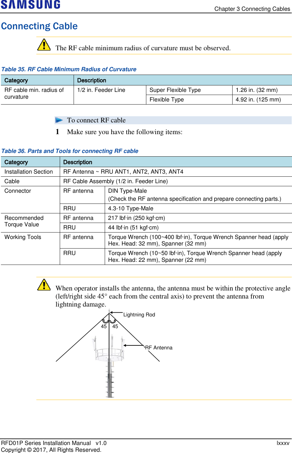
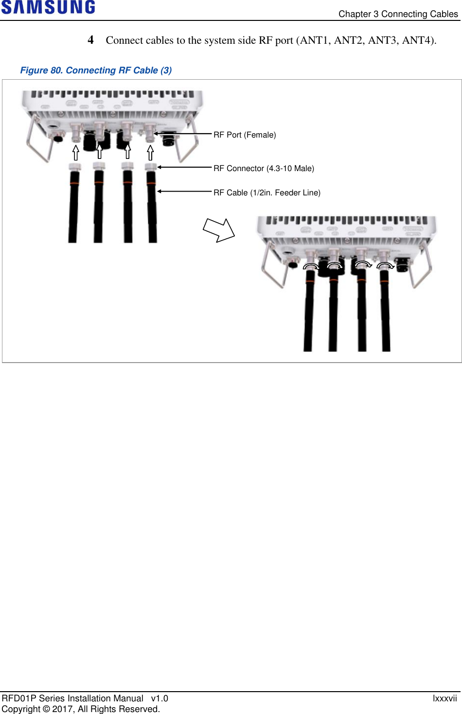
![Chapter 3 Connecting Cables RFD01P Series Installation Manual v1.0 lxxxvi Copyright © 2017, All Rights Reserved. 2 Install RF cable from the RRU to the RF antenna. Figure 78. Connecting RF Cable (1) 3 Connect cables to the RF antenna ports. Figure 79. Connecting RF Cable (2) As different connector types may be used depending on the RF antenna type, check the antenna connector before connecting the cable. Antenna Port (Female) RF Connector (DIN Male) RF Cable (1/2in. Feeder Line) RF Antenna [Bottom View] RF Cable Front](https://usermanual.wiki/Samsung-Electronics-Co/RFD01P-13A.User-Manual-2-Installation/User-Guide-3423645-Page-100.png)

![Appendix B Clean the Optical Connectors RFD01P Series Installation Manual v1.0 xcvi Copyright © 2017, All Rights Reserved. Measure the Optical Output and Connecting the Optical Connector To measure the optical output 1 Using an optical power meter check the optical output. 2 If the optical output measurement result meets the reference value, clean the connector again and connect it. 3 If the measurement result does not meet the reference value, discard the cable, replace it with a new cable, and then clean the new one and connect it to the system. [Optical Power meter] [LC/PC Plug]](https://usermanual.wiki/Samsung-Electronics-Co/RFD01P-13A.User-Manual-2-Installation/User-Guide-3423645-Page-110.png)