SK Telesys SKSN-I30-CO iDEN RF Repeater User Manual
SK Telesys Co.,Ltd. iDEN RF Repeater Users Manual
UserManual.wiki
>
SK Telesys
>
SKSN I30 CO User Manual
Users Manual
Navigation menu
Upload a User Manual
Namespaces
Wiki Guide
HTML
PDF
Info
Views
User Manual
Discussion / Help
Navigation
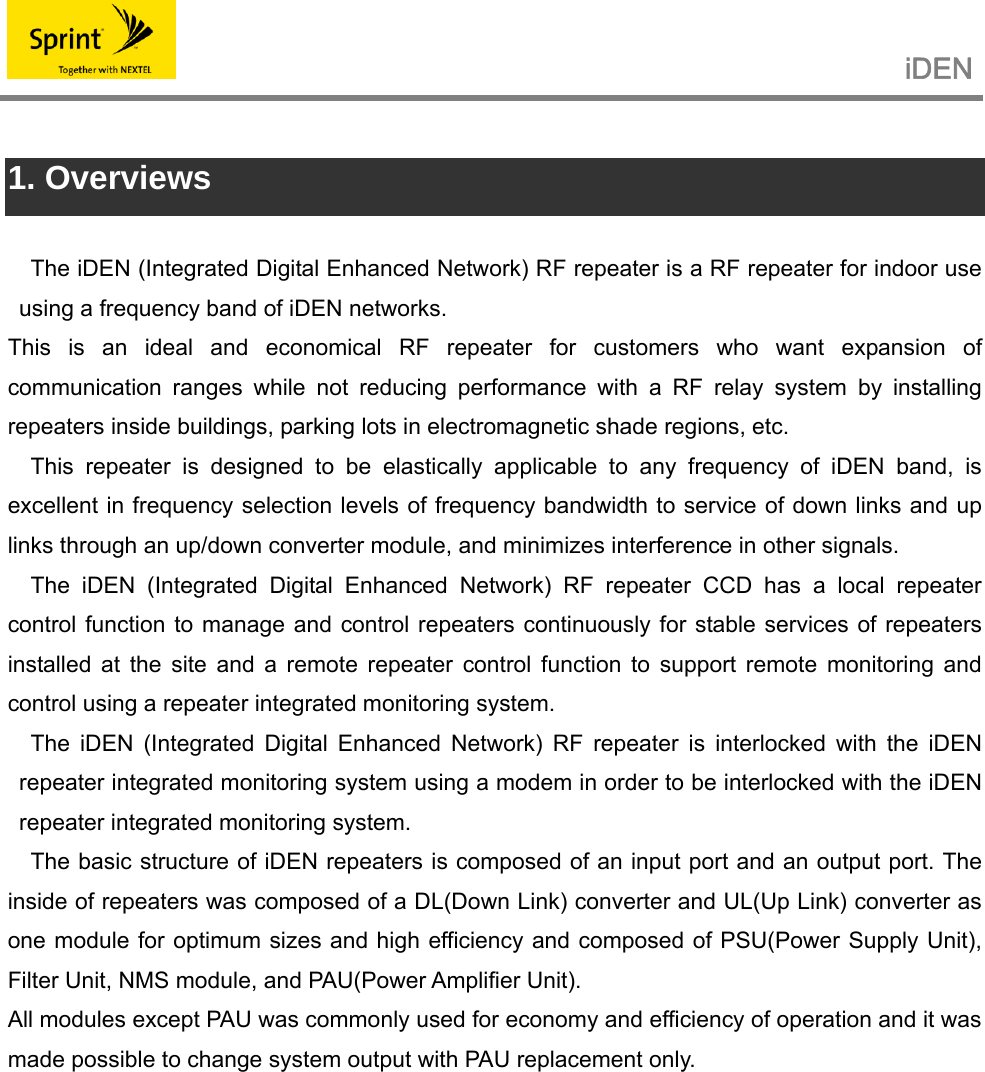
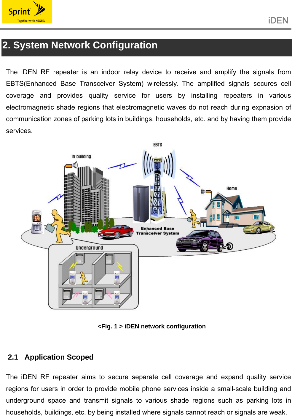
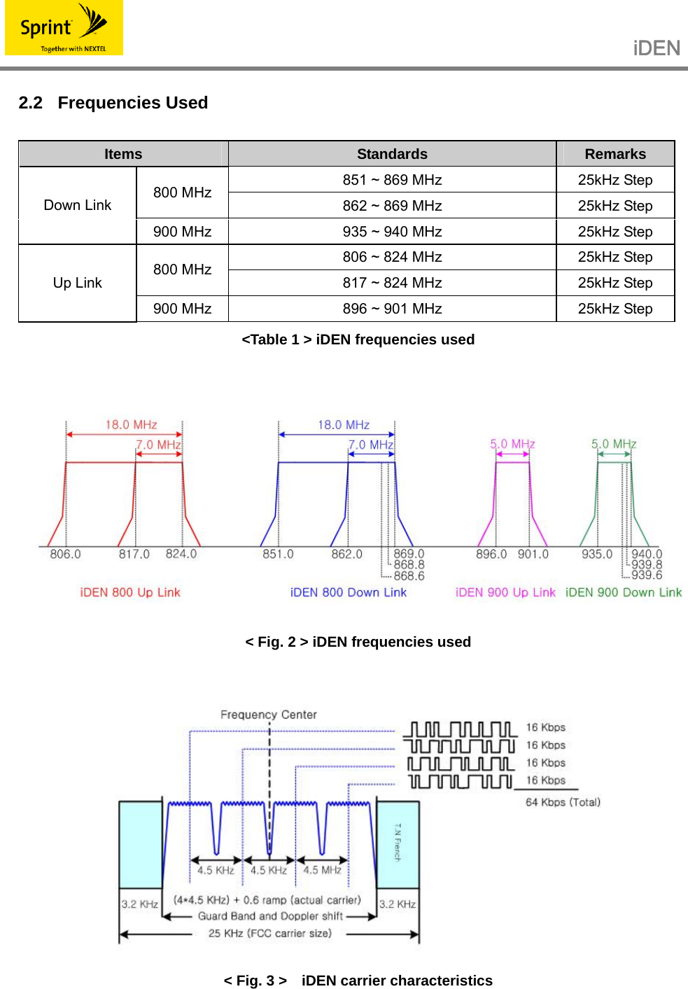
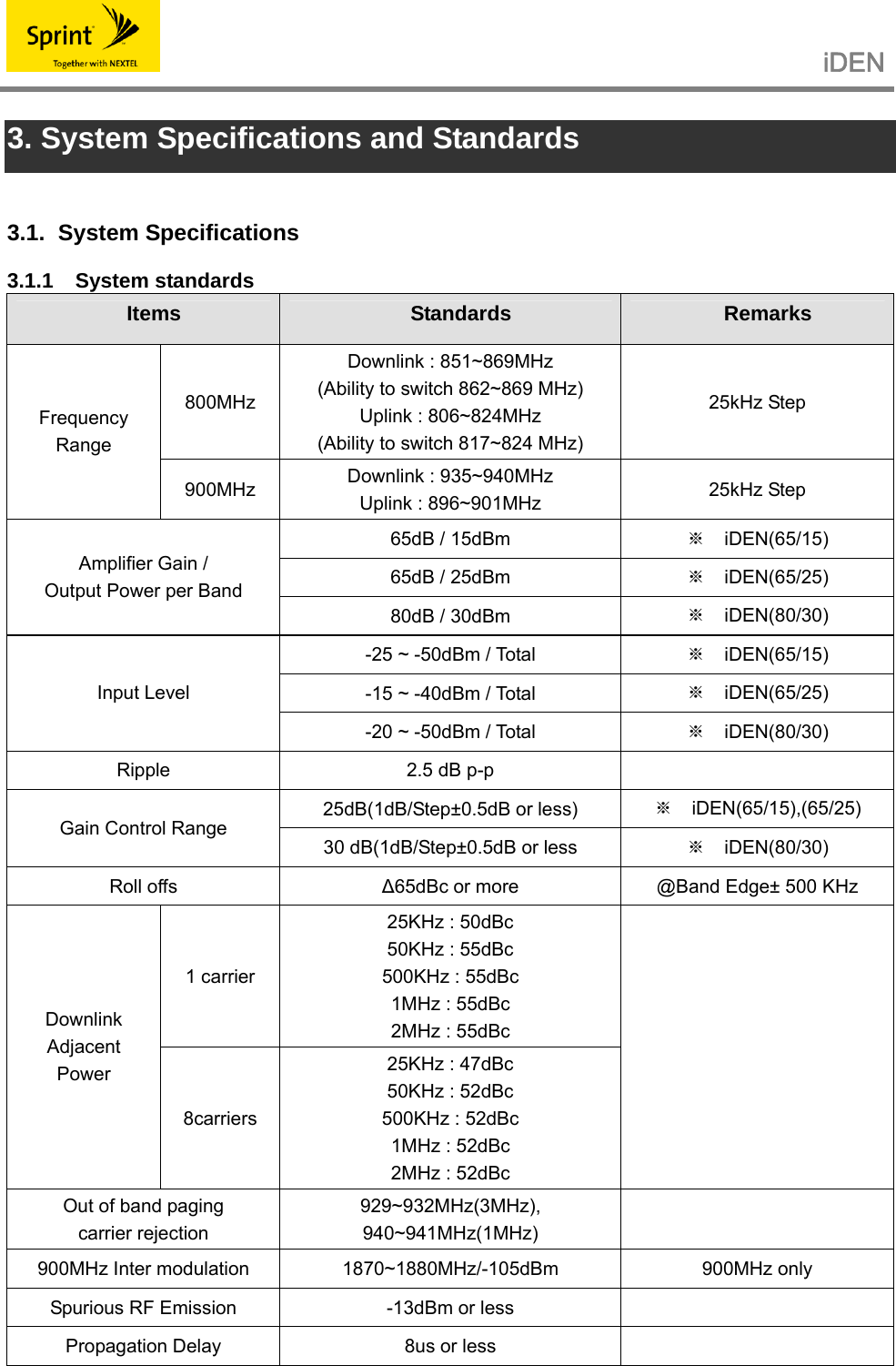
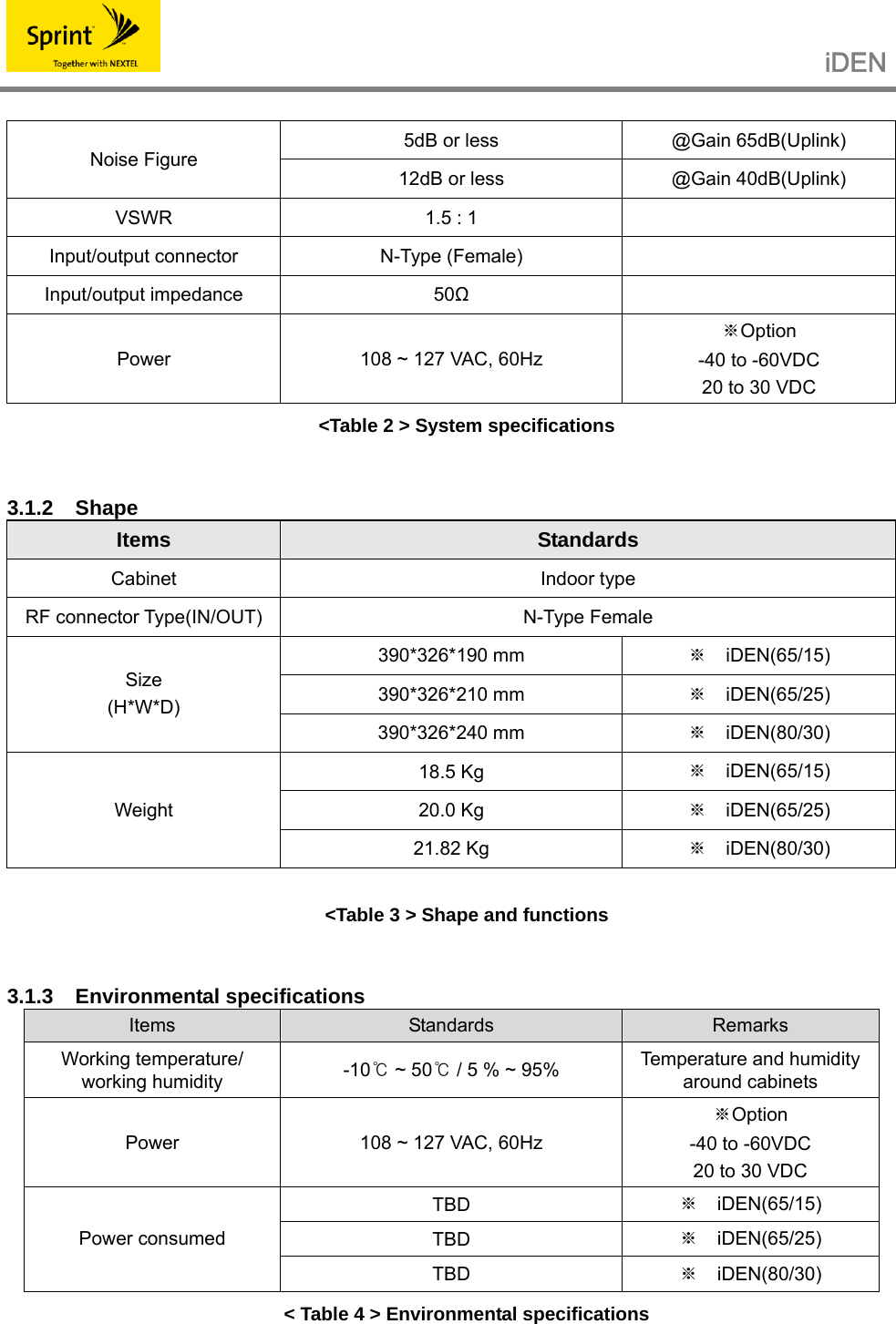
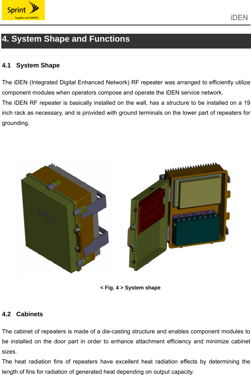
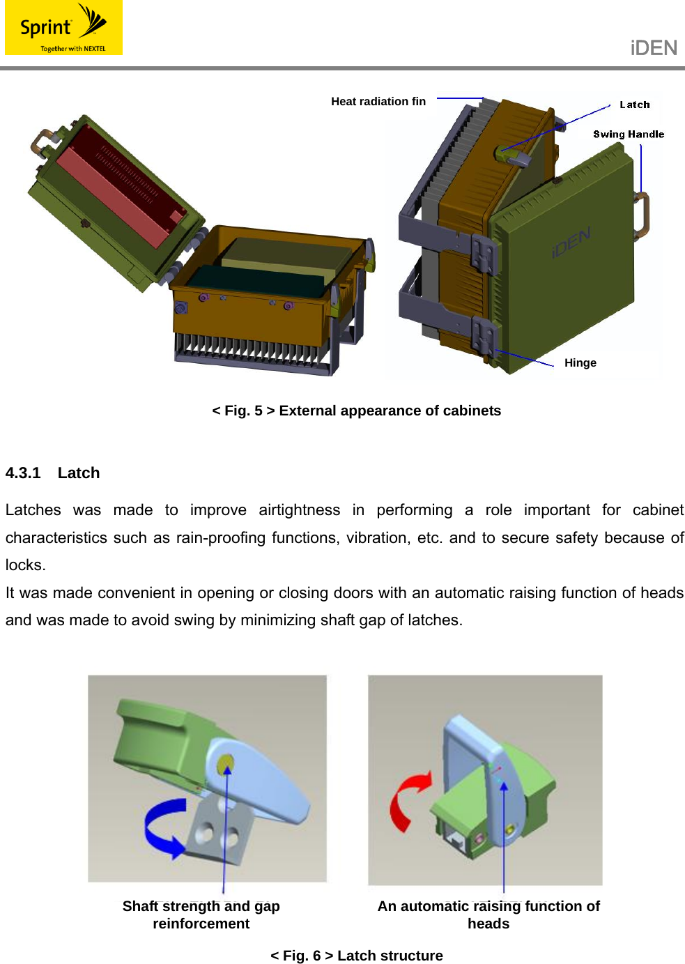
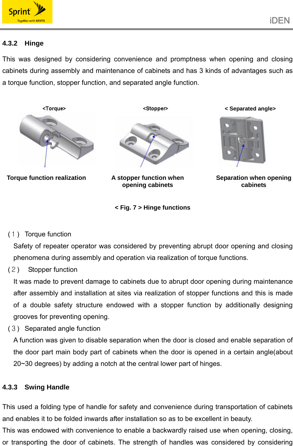
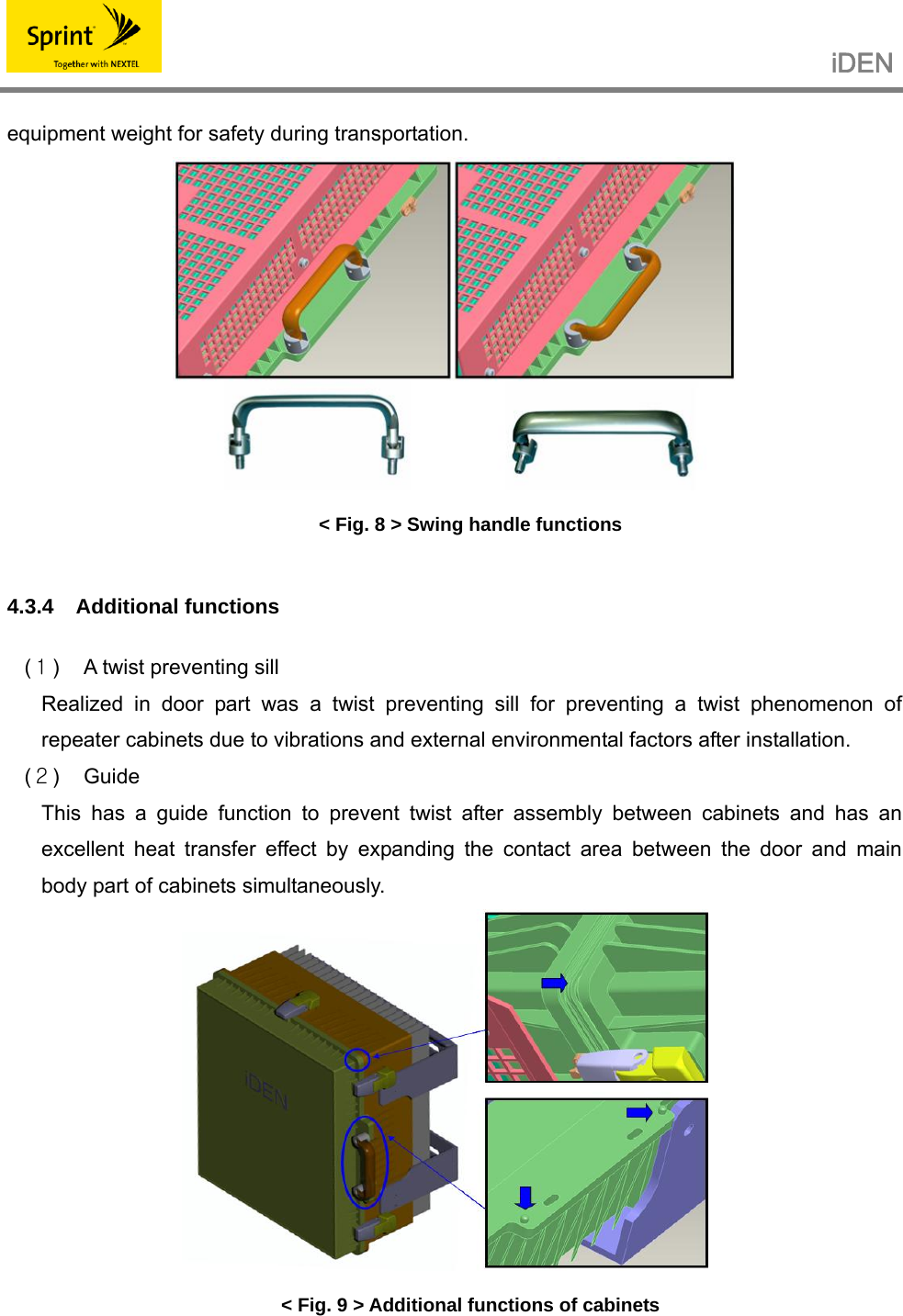
![iDEN 7. GUI (Graphic User Interface) 7.1 Program Installation Prepare the provided installation program in the same folder as below. <Fig. 11> Setup file Start program installation by double-clicking Setup.exe. Then, the following screen will show up. In order to cancel the installation, click [Cancel] in the right lower side, and in order to continue the installation, click [Next]. <Fig. 12 > Installation Start Select a folder where the program will be installed. Basically, a folder called C:\Program Files\TSEX1100 is created, allowing installation of a program there. In order to change an installation folder, select a desired folder by pressing [Browse] button and then change it.](https://usermanual.wiki/SK-Telesys/SKSN-I30-CO/User-Guide-803780-Page-24.png)
![iDEN <Fig. 13> Selection of an installation folder When an installation folder is determined, click the [Next] button. Then, a window to inform you that the preparation for installation has been completed will show up as follows. <Fig. 14> Completion of preparation for installation In order to change an installation folder, click the [Back] button, go over to the <Fig. 14> screen,](https://usermanual.wiki/SK-Telesys/SKSN-I30-CO/User-Guide-803780-Page-25.png)
![iDEN and then change the installation folder. In order to continue installation, click [Next] button. Then, a program is automatically installed as shown in <Fig.16>. <Fig. 15> Display of program installation progress It is asked whether or not to install a USB driver. In order to install a USB driver, proceed with installation according to the installation procedure by clicking the [Install] button, and if a USB driver has been already installed, cancel the installation by clicking the [Cancel] button. <Fig. 16> USB Driver Installation When the program installation is finished, an installation completion message window shows up as shown in <Fig. 18>. End the installation by clicking the [confirm] button.](https://usermanual.wiki/SK-Telesys/SKSN-I30-CO/User-Guide-803780-Page-26.png)
![iDEN <Fig. 17> USB Driver Installation 7.2 Program Start If the program is properly installed, then go to Start->Program on the Windows menu and execute TSEX1100. <Fig. 18 > Program start 7.3 Status Inquiry/Setting As soon as the program is executed, a serial port is automatically opened at a baudrate 38400bps. In order to change the comport, suspend the present status by pressing the [Port Close] button, change it into the desired port among COM 1 ~ COM 8, and then open the port by clicking the [Port Open] button. You can know the communication status through TXD / RXD LED in the right upper side. If TXD / RXD flickers in turns, it means that communication is properly being realized. PC displays the status values on the screen while automatically polling with the system in about](https://usermanual.wiki/SK-Telesys/SKSN-I30-CO/User-Guide-803780-Page-27.png)
![iDEN 1 second interval. 7.3.1 Status Inquiry If the type in the left upper side is iDEN, an iDEN related item appears on the screen as shown in the figure below. <Fig. 19> An iDEN status inquiry screen Functions of each button are as follows. Port Open / Close Opening/closing a communication port Debug Opening a window to show communication contents Download Opening a download window Set Control setting Exit Program end 7.3.2 Status Setting Changing the value of the item to change when controlling status changes the item text into blue color as shown in the figure below, and pressing the [Set] button changes values for the item whose text has changed into blue color.](https://usermanual.wiki/SK-Telesys/SKSN-I30-CO/User-Guide-803780-Page-28.png)
![iDEN <Fig. 20> An iDEN status setting screen 7.4 DOWNLOAD 7.4.1 Preparation for Download Clicking the Download button on the status/monitoring screen enables F/W Download. Clicking the Download button on the status/monitoring screen shows a window as shown in the figure below. <Fig. 21> A download preparation window Click the [File Open] button. If you want to end it, click the [Exit] button.](https://usermanual.wiki/SK-Telesys/SKSN-I30-CO/User-Guide-803780-Page-29.png)
![iDEN 7.4.2 File Open Clicking the [File Open] button shows a File Open window as shown in the figure below. <Fig. 22> File Open Find and click a file to download whose extension is ".bin” or directly enter the name of a file to download on the file name column and then click [OK]. Then, the file information(file path, file name, file size, total frame) will show up on the download preparation window as shown in the figure below. <Fig. 23> Completion of download preparation](https://usermanual.wiki/SK-Telesys/SKSN-I30-CO/User-Guide-803780-Page-30.png)
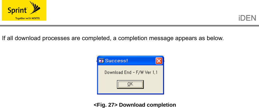
![iDEN 7.4.3 Download Start Clicking the [Start] button on the upper side of the above <Fig. 24> starts downloading and shows a download progress window as shown in the figure below to show the download progress situations. <Fig. 24> A download progress screen Pressing the [Cancel] button cancels download. If downloading is not properly realized, a warning window shows up as shown in the figure below. <Fig. 25> A message to notify you of download failure 7.4.4 Completion of Download If download is completed, a wait window shows up while equipment is being initialized. Wait until a completion message appears. <Fig. 26> Flash write wait](https://usermanual.wiki/SK-Telesys/SKSN-I30-CO/User-Guide-803780-Page-31.png)