SEA COM SEA157S VHF Marine Radiotelephone/Class A DSC GMDSS User Manual OPR 157SA Rev1a
SEA COM CORPORATION VHF Marine Radiotelephone/Class A DSC GMDSS OPR 157SA Rev1a
UserManual.wiki
>
SEA COM
>
SEA157S User Manual
>
Users Manual
Contents
1.
Maintenance/Service manual
2.
Users Manual
3.
RF exposure safety warning for operators manual
Users Manual
Navigation menu
Upload a User Manual
Namespaces
Wiki Guide
HTML
PDF
Info
Views
User Manual
Discussion / Help
Navigation
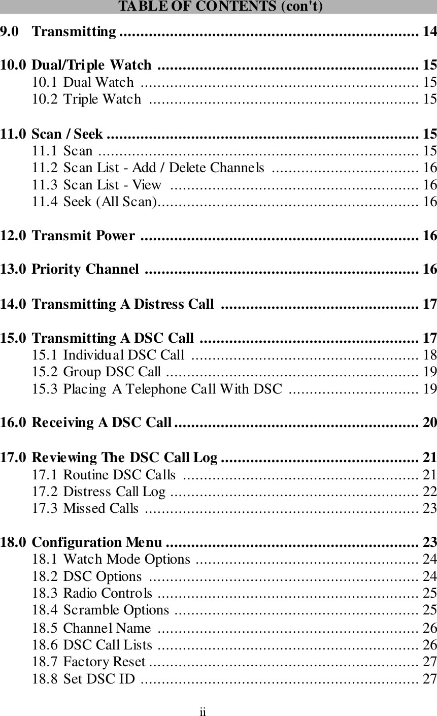
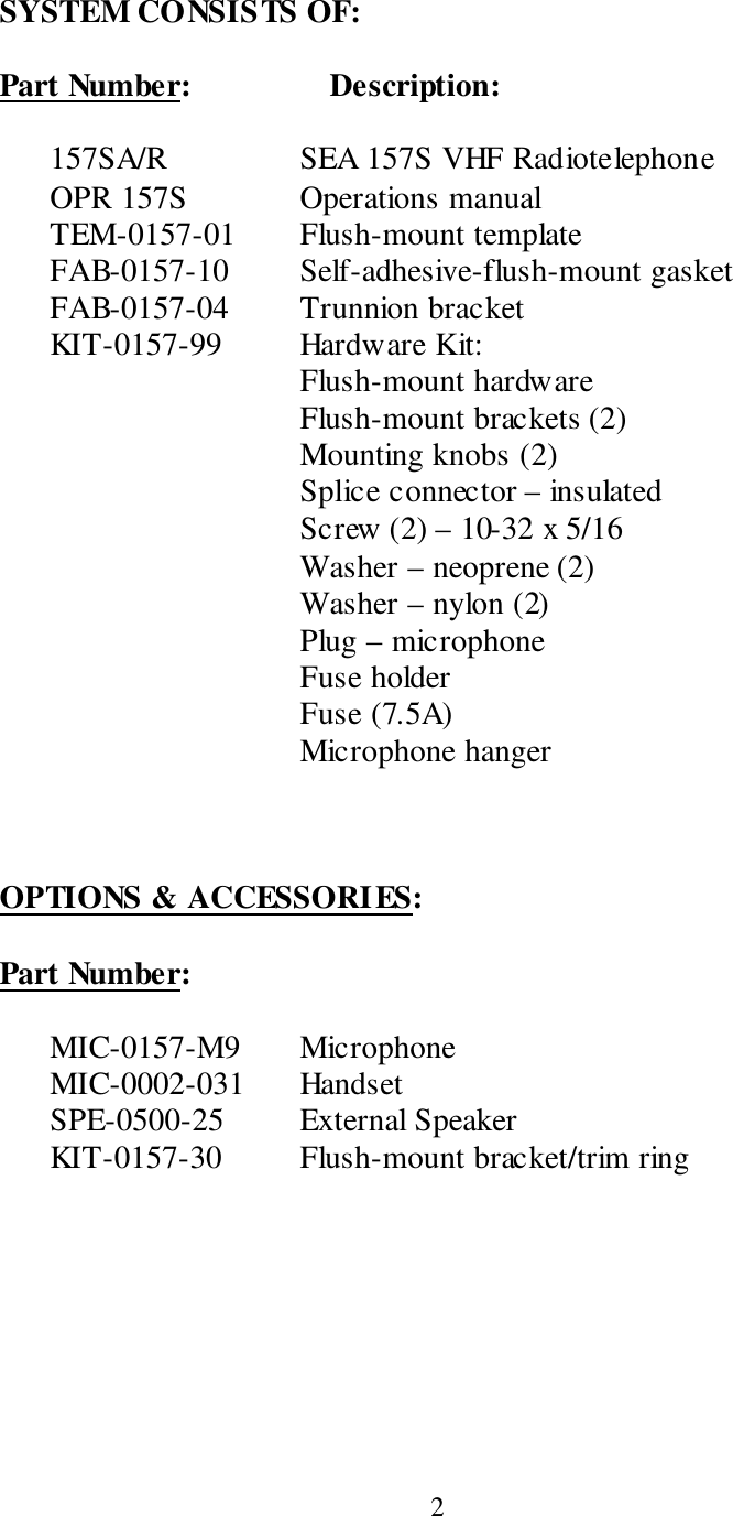
![3 TECHNICAL FEATURES AND SPECIFICATIONS Figure 1.1 ELECTRICAL SPECIFICATIONS 12 Vdc +30% -10% <1.0 – Amp Receive <7.0 – Amp Transmit WIRING DIAGRAMS Main Cable Color Code Signal 1 - RED - 12 Vdc (+) 2 - BLACK - 12 Vdc (-) 3 - BLUE* - Audio Out 4 - ORANGE* - Internal Speaker (IN) 5 - YELLOW - (VDR) 600 Ohm Balanced 6 - GREEN - (VDR) 600 Ohm Balanced 7 - VIOLET - (VDR) Ground 8 - GRAY - AUX remote distress key 9 - BROWN - PTT 10 - WHITE/RED - Mute 11 - WHITE - Microphone Input 12 - SHIELD - Microphone Input GND *NOTE: Audio Out – (BLUE) and Internal Speaker (IN) - (ORANGE) wires must be connected in order for internal speaker operation. Dimensions: 3.6” H x 9.6” W x 2.8” D Weight: 3 lbs (1.4 kg) 10.6 6 [270.8]9.60 [243.8]4.25 [108.0]3.60 [91.3]2.56 [64.9] 1.63 [41.5]](https://usermanual.wiki/SEA-COM/SEA157S.Users-Manual/User-Guide-1376838-Page-7.png)