Rohde and Schwarz NV830X UHF 1.8kW maximum Digital TV transmitter User Manual 32 SLX8000 12 12 07 01 00
Rohde & Schwarz Inc UHF 1.8kW maximum Digital TV transmitter 32 SLX8000 12 12 07 01 00
Contents
- 1. User Manual Part 1
- 2. User Manual Part 2
- 3. User Manual Part 3
User Manual Part 3

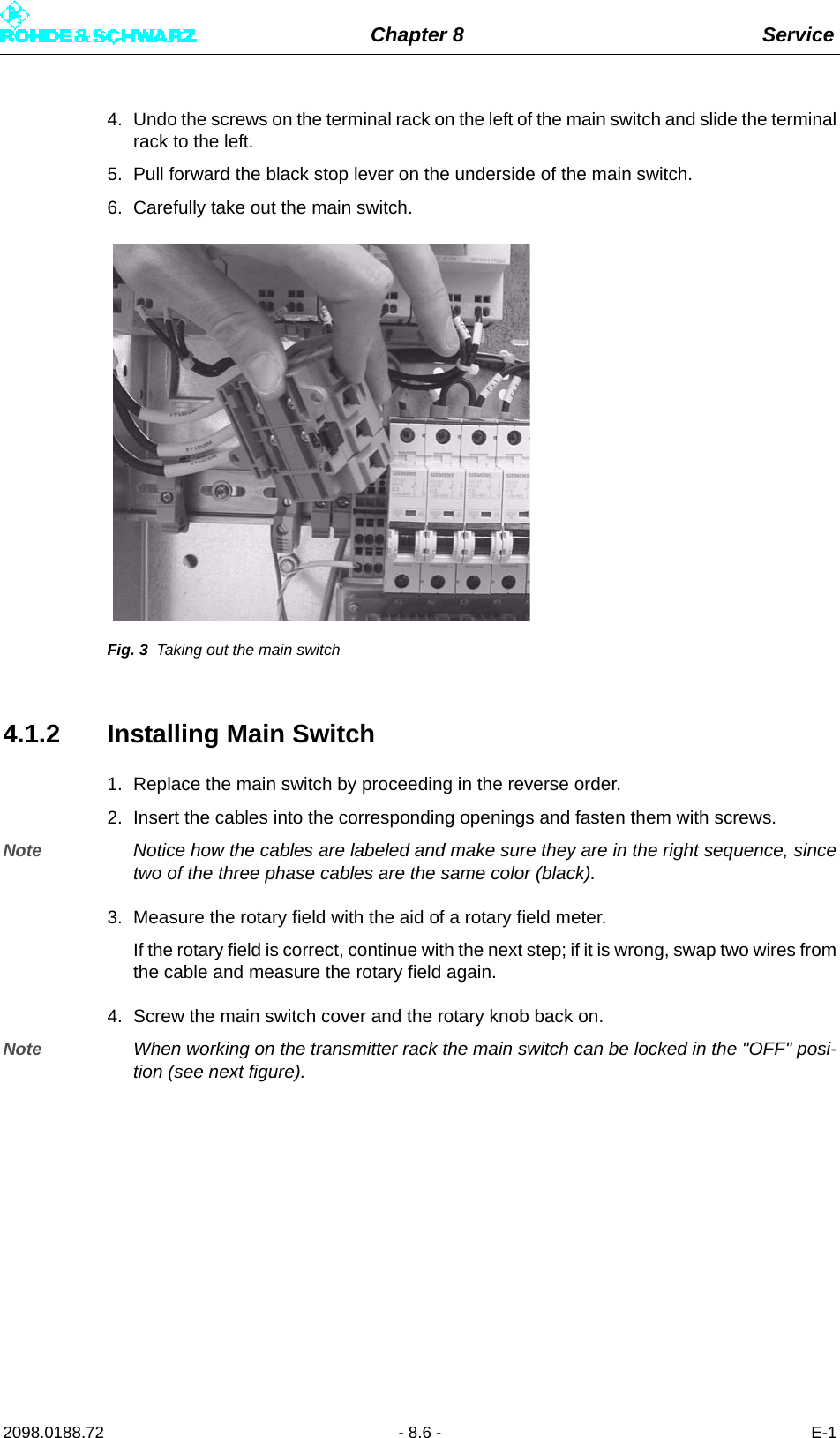
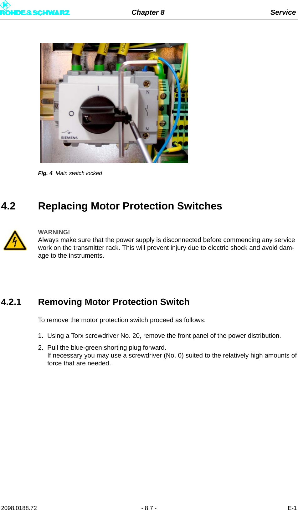
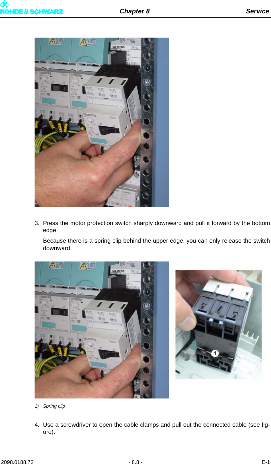
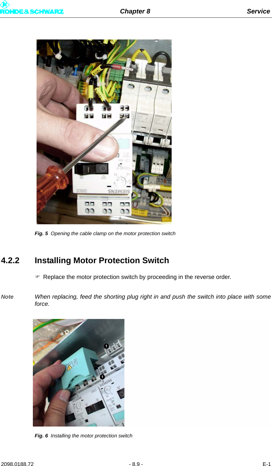
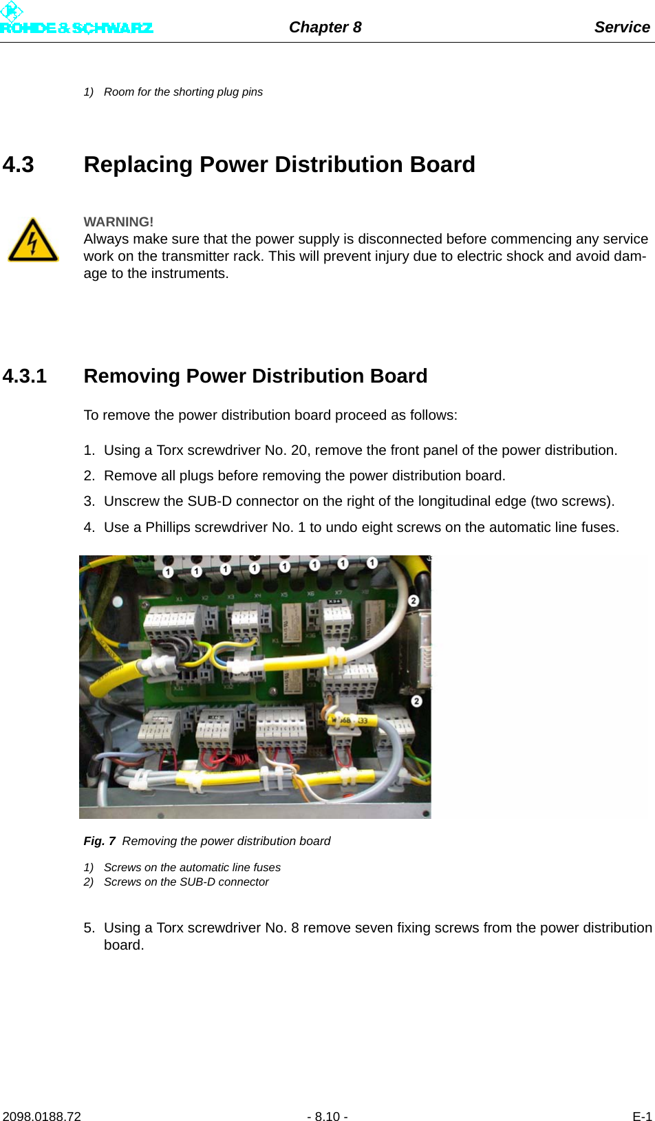
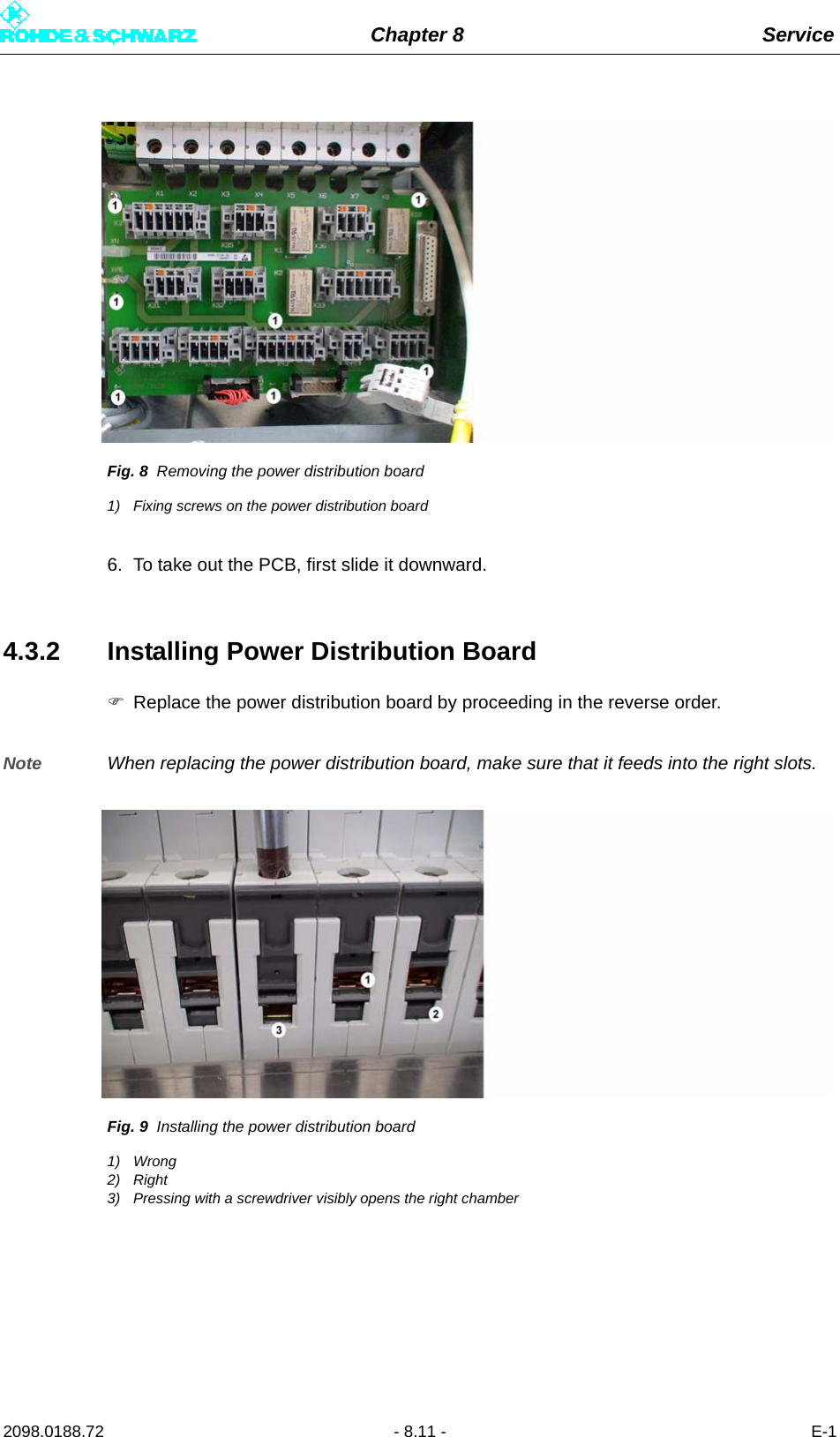
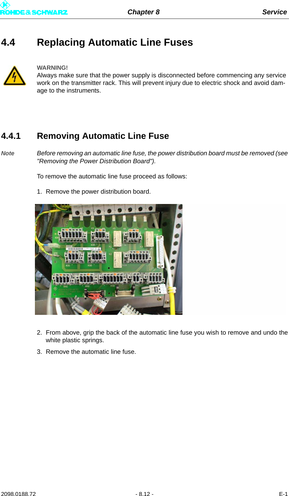
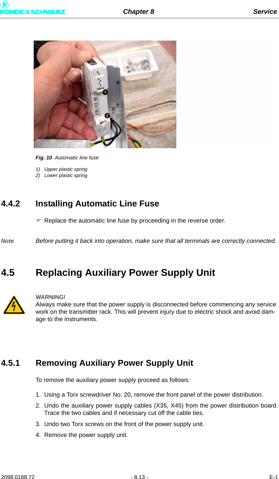
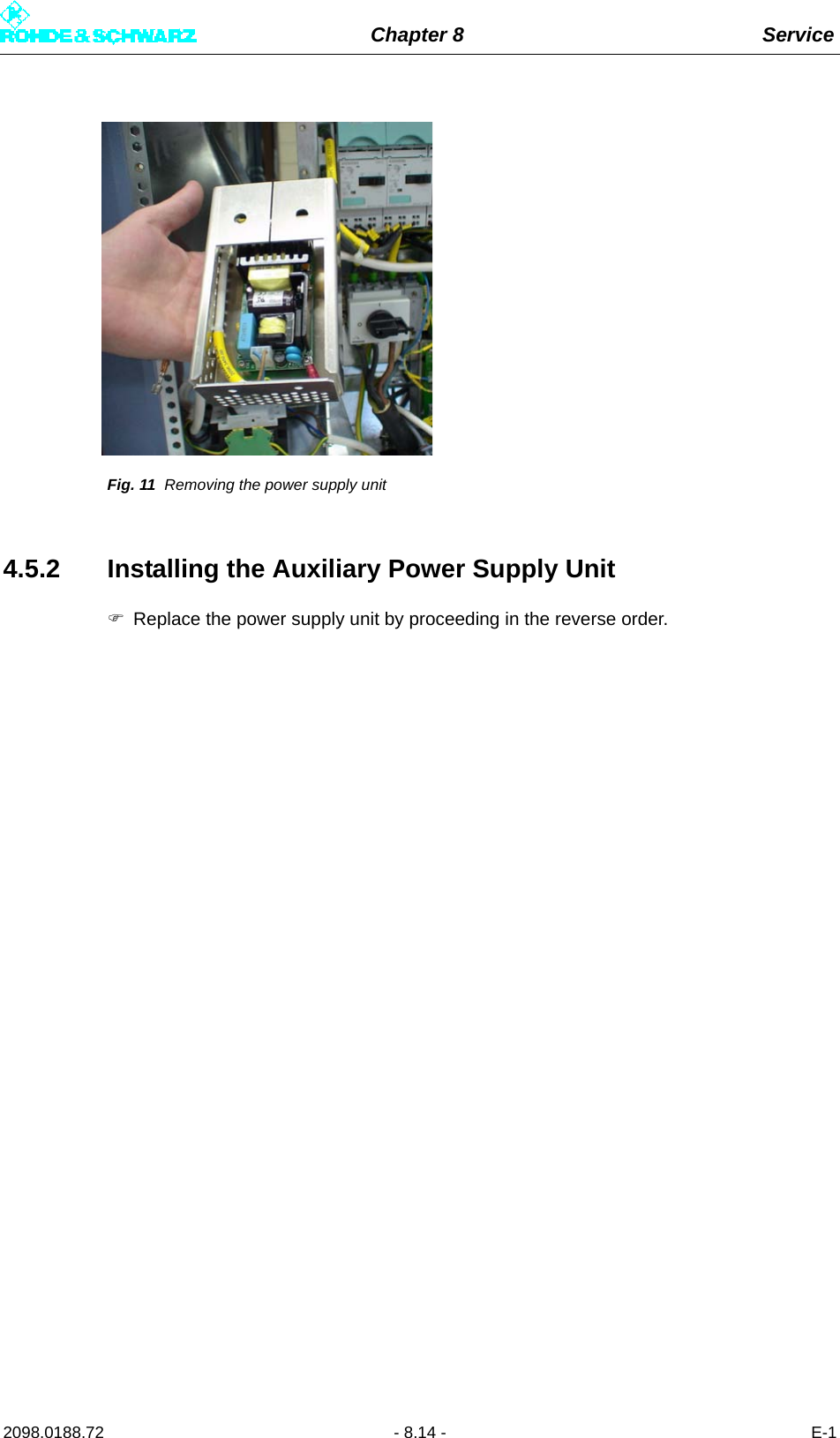
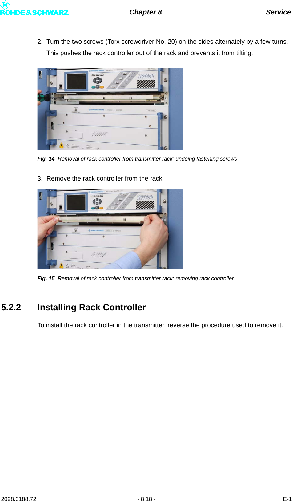
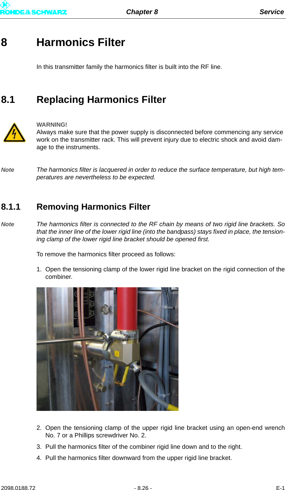
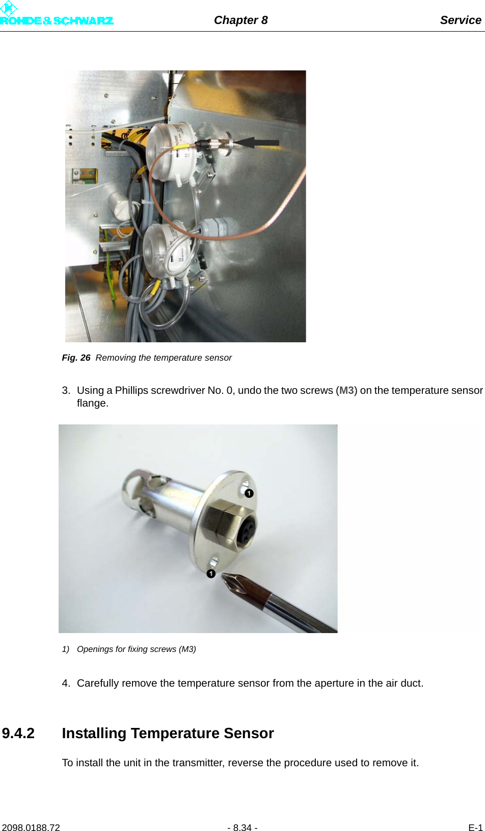
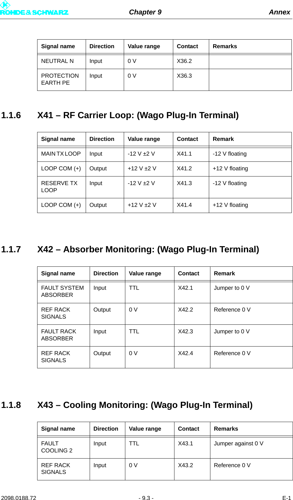
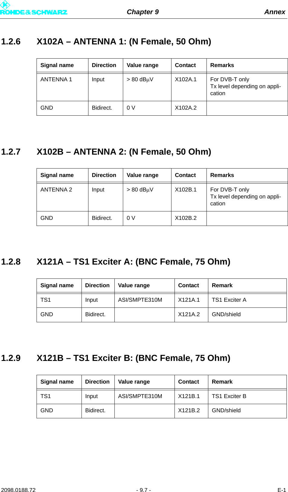
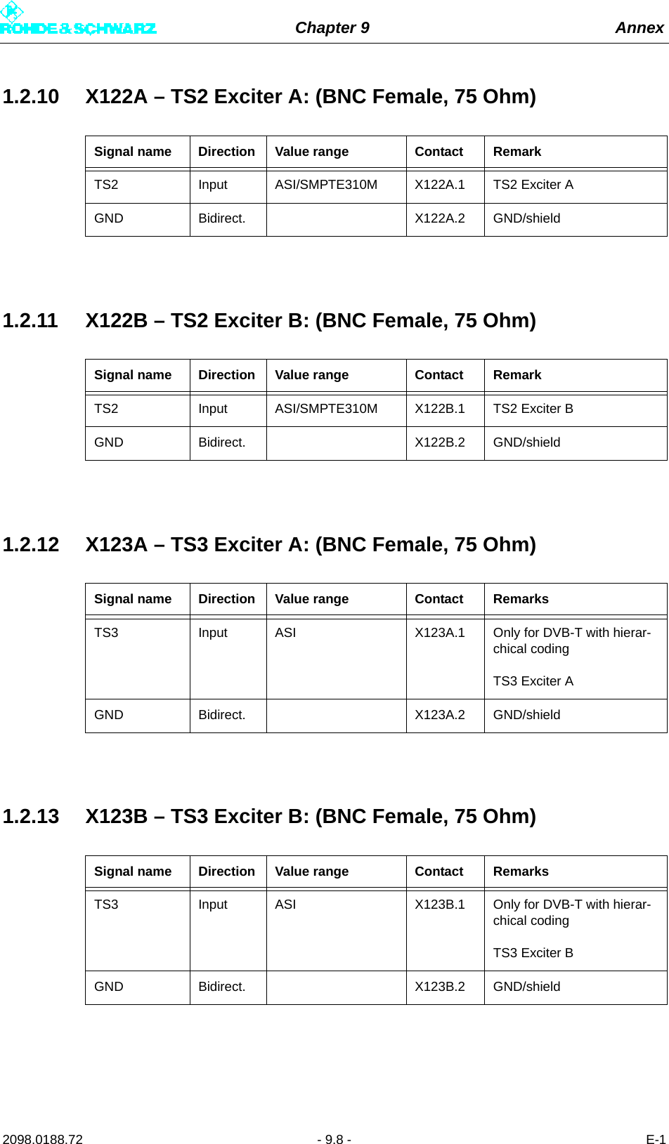
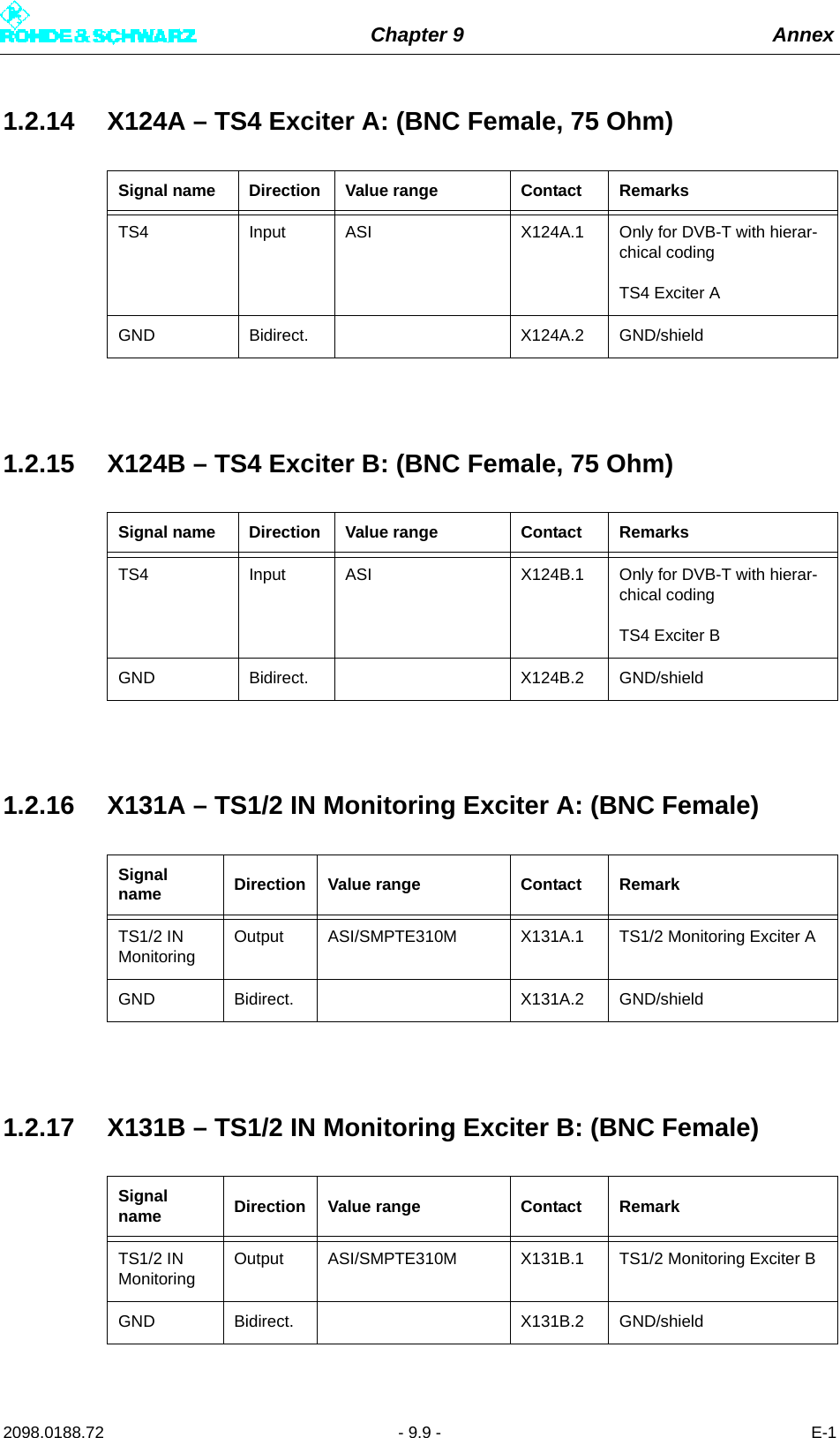
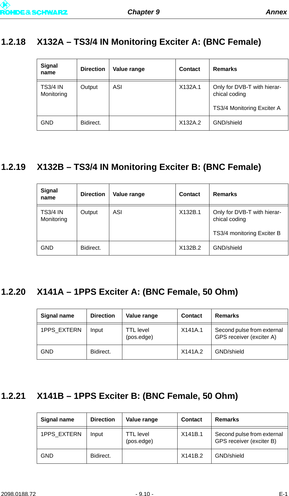
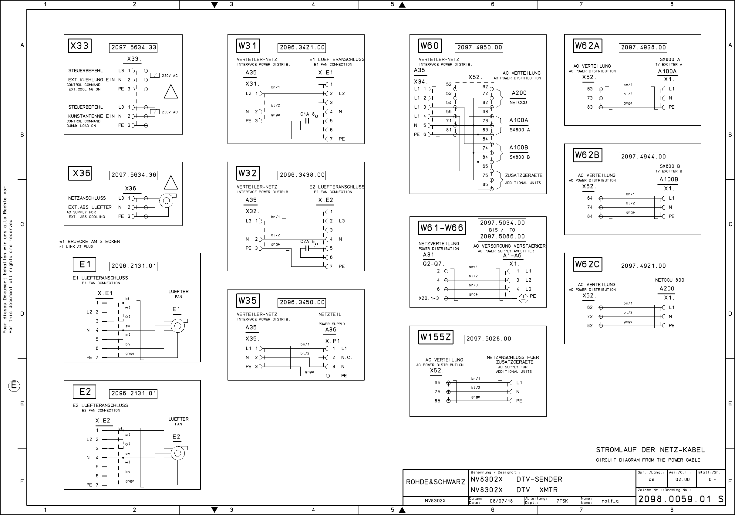
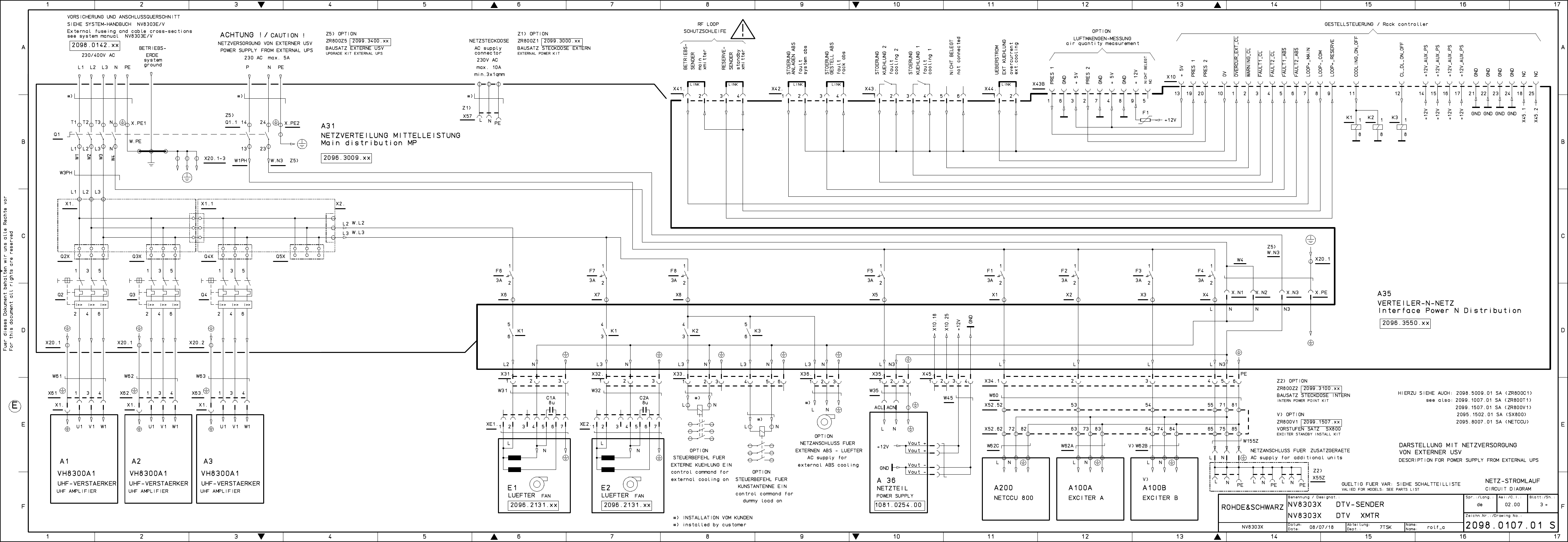
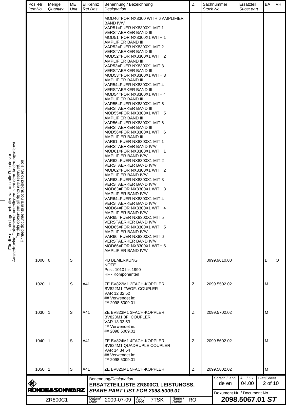
![Chapter 9 Annex2098.0188.72 - 9.1 - E-11 Interface Description1.1 Front-Panel Interfaces1.1.1 Q1 – AC Supply Input / Protective Earth1.1.2 X57 – Optional Connector Kit ZR800Z11.1.3 X33 – External Fan (Optional): (Wago Plug-In Terminal)Signal name Direction Value range Contact RemarkPHASE L1 Input 400 V ±15% Q1.T1 Three-phase current input L1PHASE L2 Input 400 V ±15% Q1.T2 Three-phase current input L2PHASE L3 Input 400 V ±15% Q1.T3 Three-phase current input L1NEUTRAL N Input 0 V Q1.N Neutral-conductor input NPROTECTION EARTH PEInput 0 V X.PE PE terminalPROTECTION EARTH PEInput 0 V PE pin PE stationSignal name Direction Value range Contact RemarkPHASE L1 Input 230 V X57.L1 Separate circuitNEUTRAL N Input 0 V X57.NPROTECTION EARTH PEInput 0 V X57.PESignal name Direction Value range Contact RemarkPHASE L1 Input 230 V X33.1 Line protection F8 [3A]NEUTRAL N Input 0 V X33.2](https://usermanual.wiki/Rohde-and-Schwarz/NV830X.User-Manual-Part-3/User-Guide-1672828-Page-59.png)
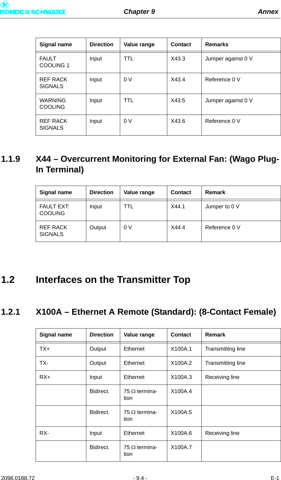
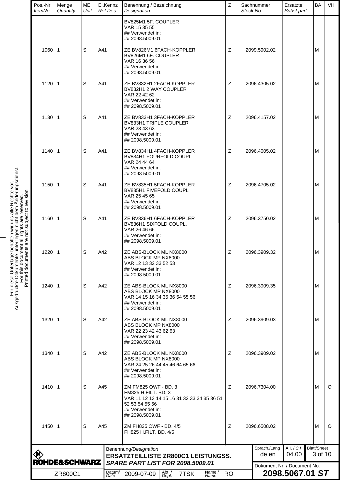
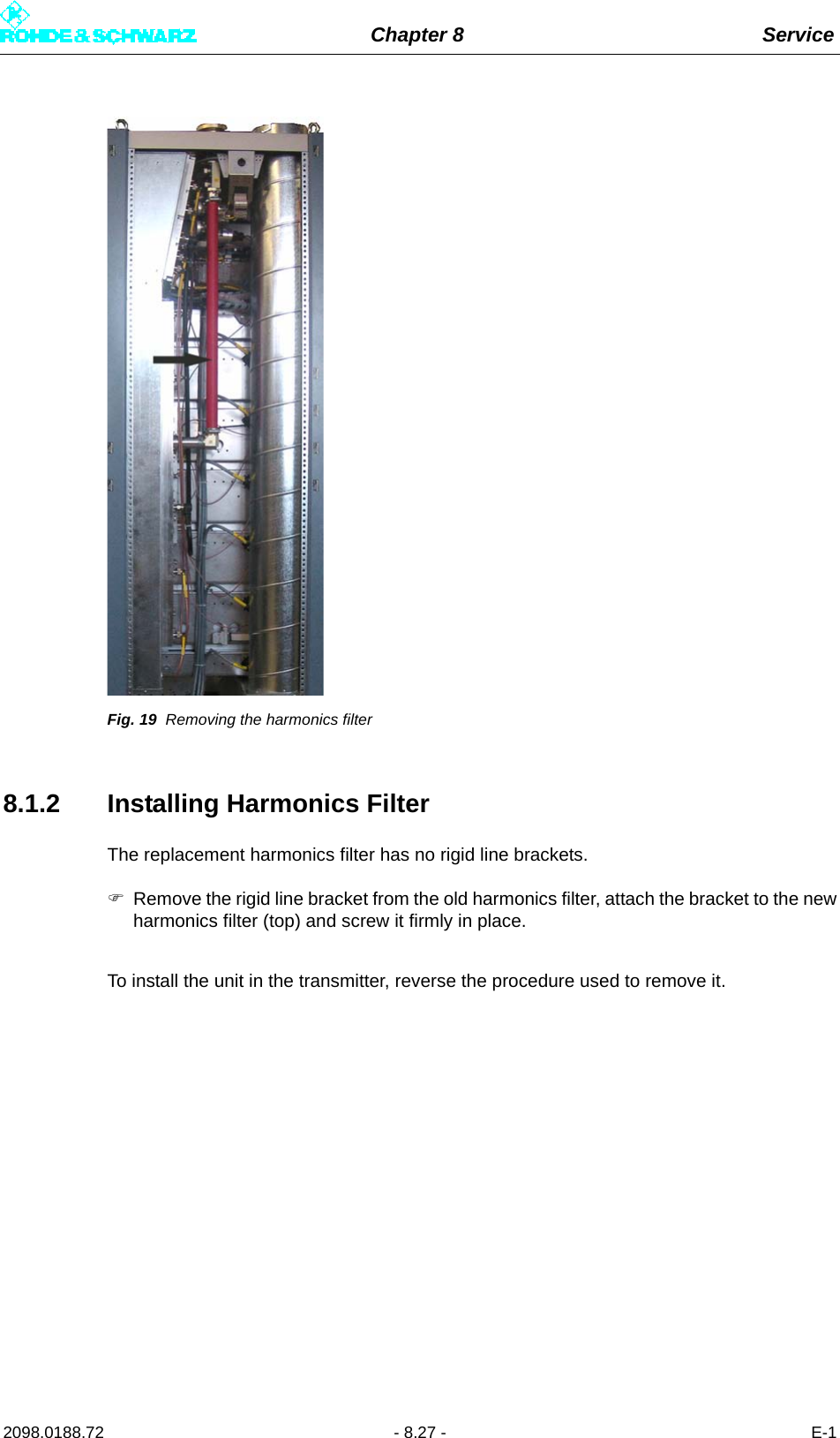
![Chapter 9 Annex2098.0188.72 - 9.2 - E-1External fan for dummy antenna (optional): (Wago plug-in terminal)1.1.4 X34 – AC Power Supply for Control Units and Exciters (Single-Phase): (Wago Plug-In Terminal)1.1.5 X36 – External Absorber Cooling System (Optional): (Wago Plug-In Terminal)PROTECTION EARTH PEInput 0 V X33.3Signal name Direction Value range Contact RemarkPHASE L1 Input 230 V X33.4 Line protection F8 [3A]NEUTRAL N Input 0 V X33.5PROTECTION EARTH PEInput 0 V X33.6Signal name Direction Value range Contact RemarksPHASE L1 Output 230 V X34.1 Line fuse F1 [3A] R&S NetCCU800 connectionPHASE L1 Output 230 V X34.2 Line fuse F2 [3A] Sx800 A connectionPHASE L1 Output 230 V X34.3 Line fuse F3 [3A] Sx800 B connectionPHASE L1 Output 230 V X34.4 Line fuse F4 [3A] Add-on equipment connec-tionNEUTRAL N Input 0 V X34.5PROTECTION EARTH PEInput 0 V X34.6Signal name Direction Value range Contact RemarksPHASE L3 Output 230 V X36.1 Line fuse F8 [3A]Signal name Direction Value range Contact Remark](https://usermanual.wiki/Rohde-and-Schwarz/NV830X.User-Manual-Part-3/User-Guide-1672828-Page-60.png)