Remotesolution RH55K RF IR Converter User Manual
Remote Solution Co., Ltd. RF IR Converter Users Manual
UserManual.wiki
>
Remotesolution
>
RH55K User Manual
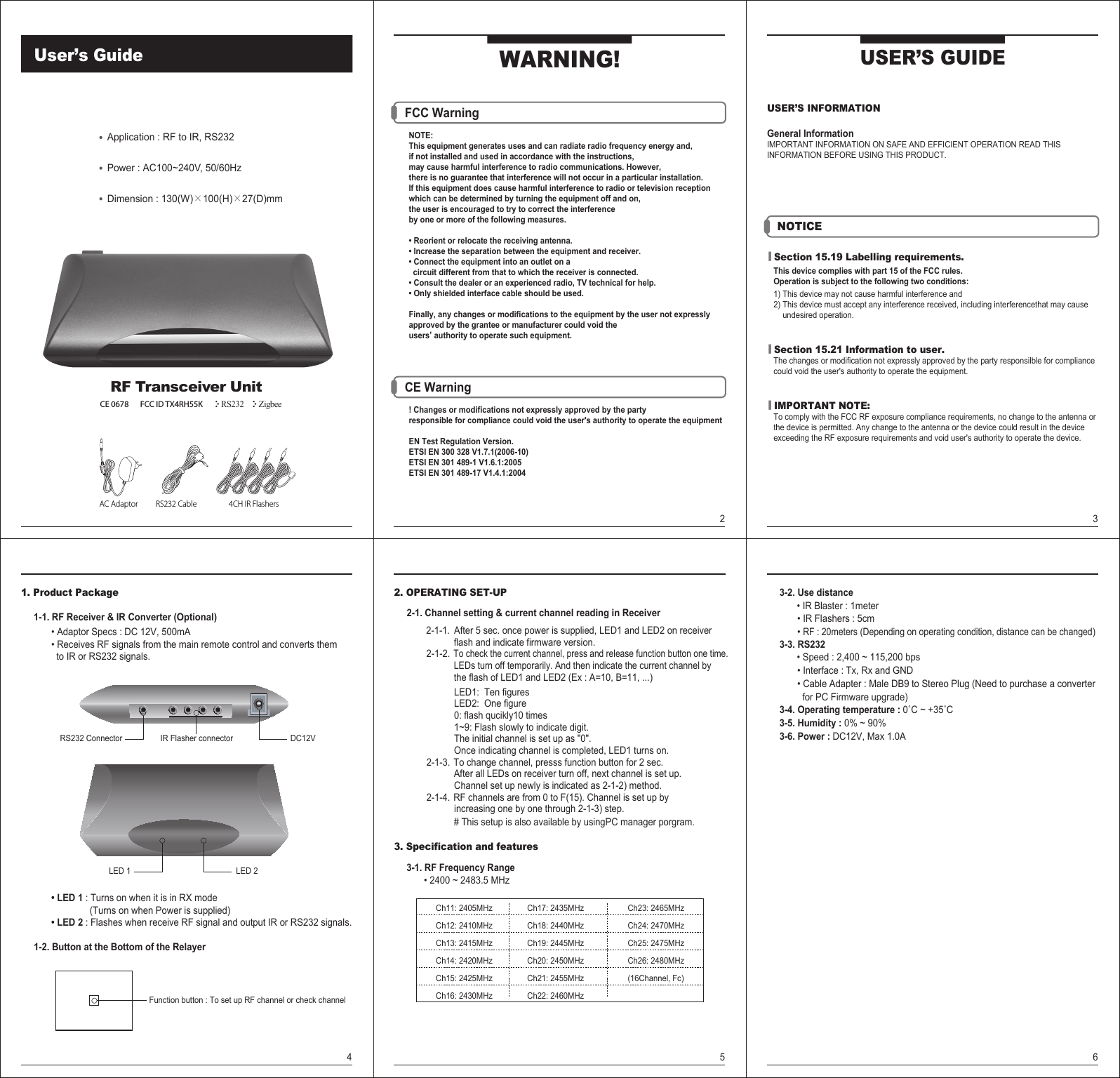
Users Manual
Navigation menu
Upload a User Manual
Namespaces
Wiki Guide
HTML
PDF
Info
Views
User Manual
Discussion / Help
Navigation