Raytheon Anschuetz High Seas GEMRM-10U X-Band Radar Transceiver User Manual Dokument
Raytheon Anschuetz GmbH High Seas Products X-Band Radar Transceiver Dokument
UserManual.wiki
>
Raytheon Anschuetz High Seas
>
GEMRM-10U User Manual
>
Users Manual Part 1
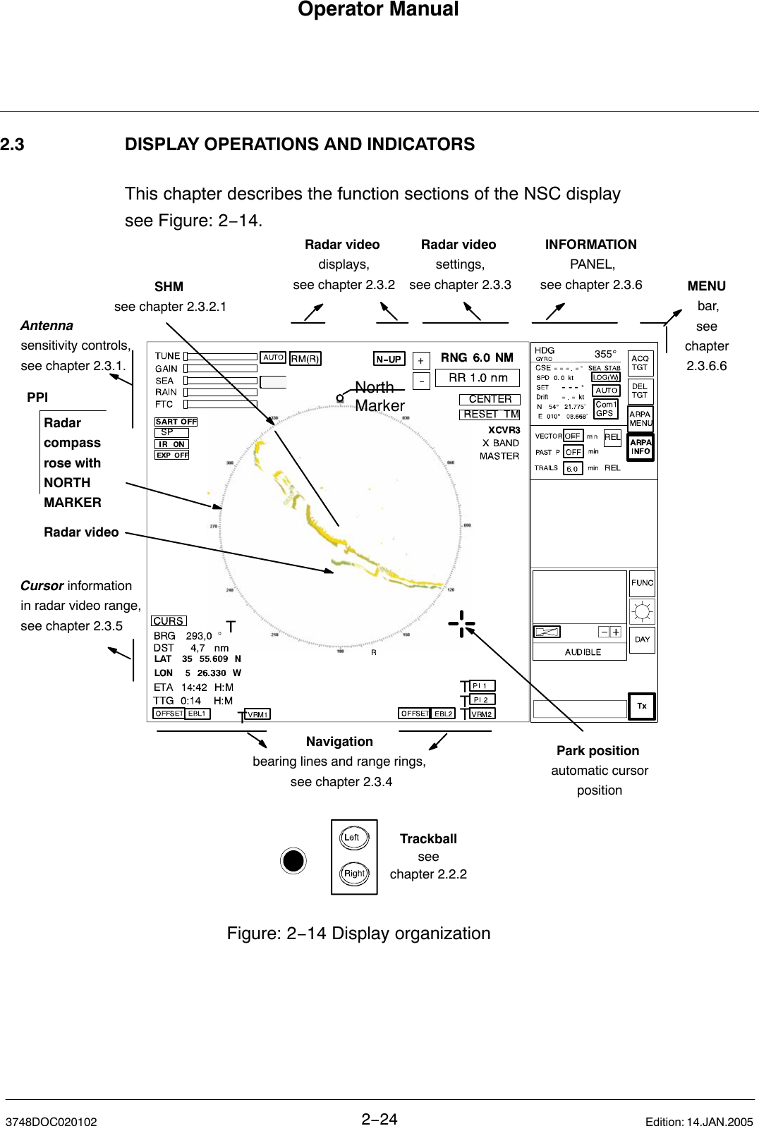
Contents
1.
Users Manual Part 1
2.
Users Manual Part 2
Users Manual Part 1
Navigation menu
Upload a User Manual
Namespaces
Wiki Guide
HTML
PDF
Info
Views
User Manual
Discussion / Help
Navigation