Raveon Technologies orporated M7-UC DART Data Modem M7UC User Manual
Raveon Technologies, Incorporated DART Data Modem M7UC
UserManual.wiki
>
Raveon Technologies orporated
>
M7 UC User Manual
User Manual
Navigation menu
Upload a User Manual
Namespaces
Wiki Guide
HTML
PDF
Info
Views
User Manual
Discussion / Help
Navigation

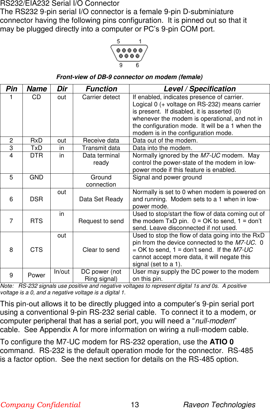
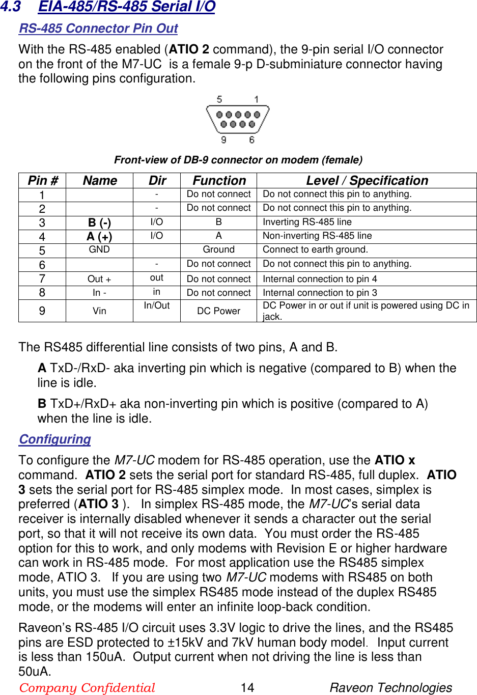
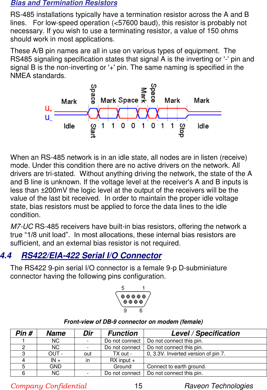
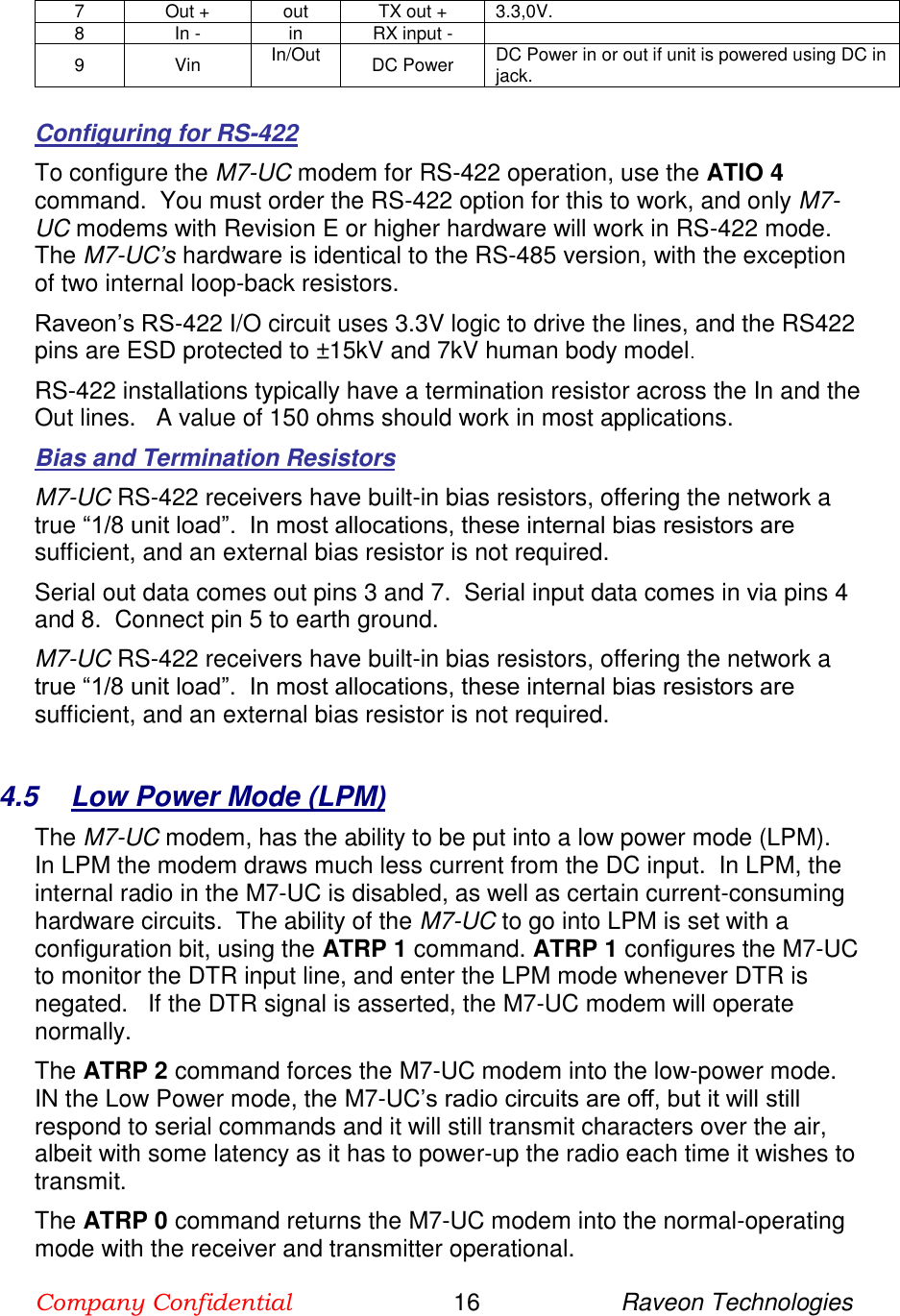
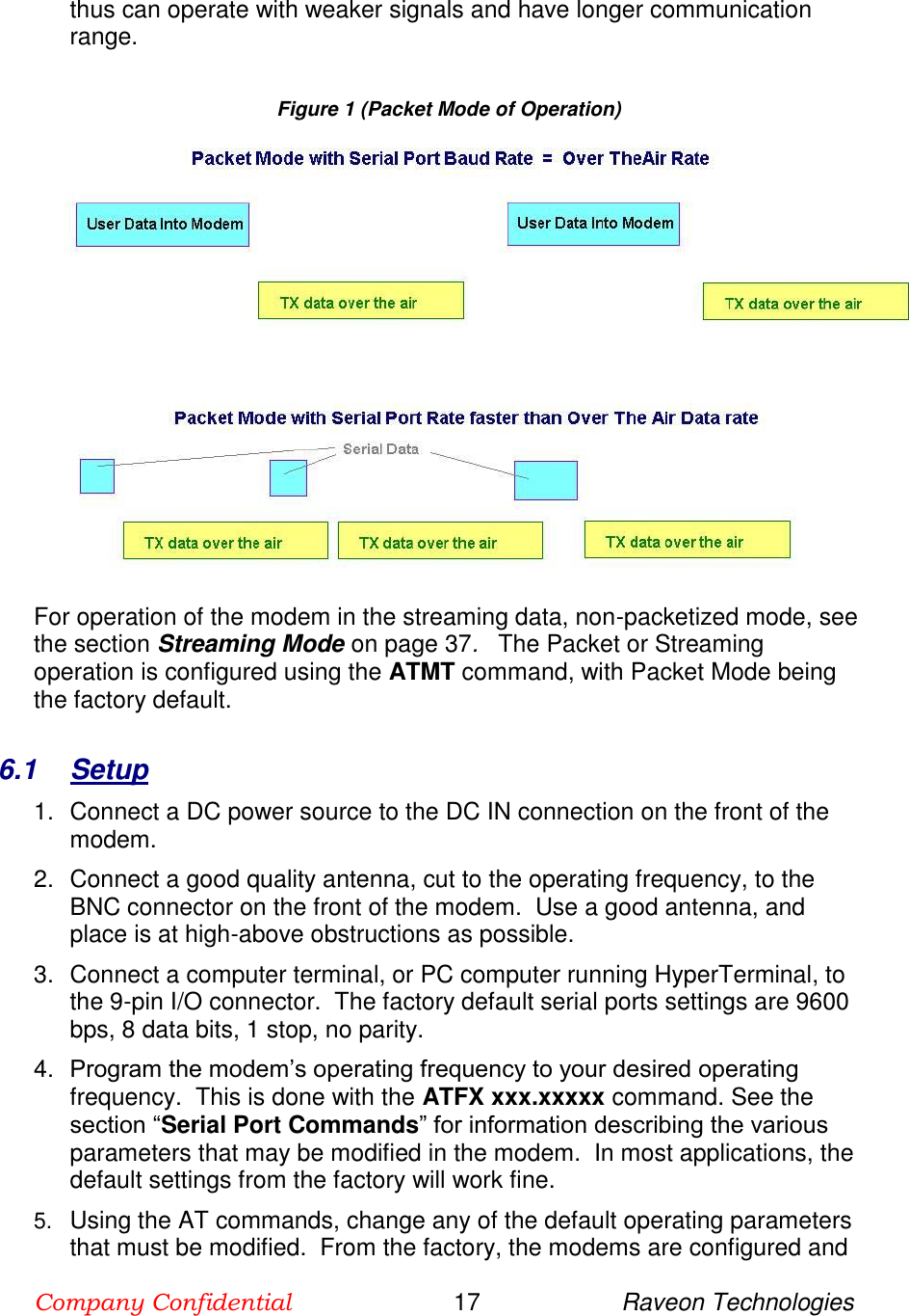
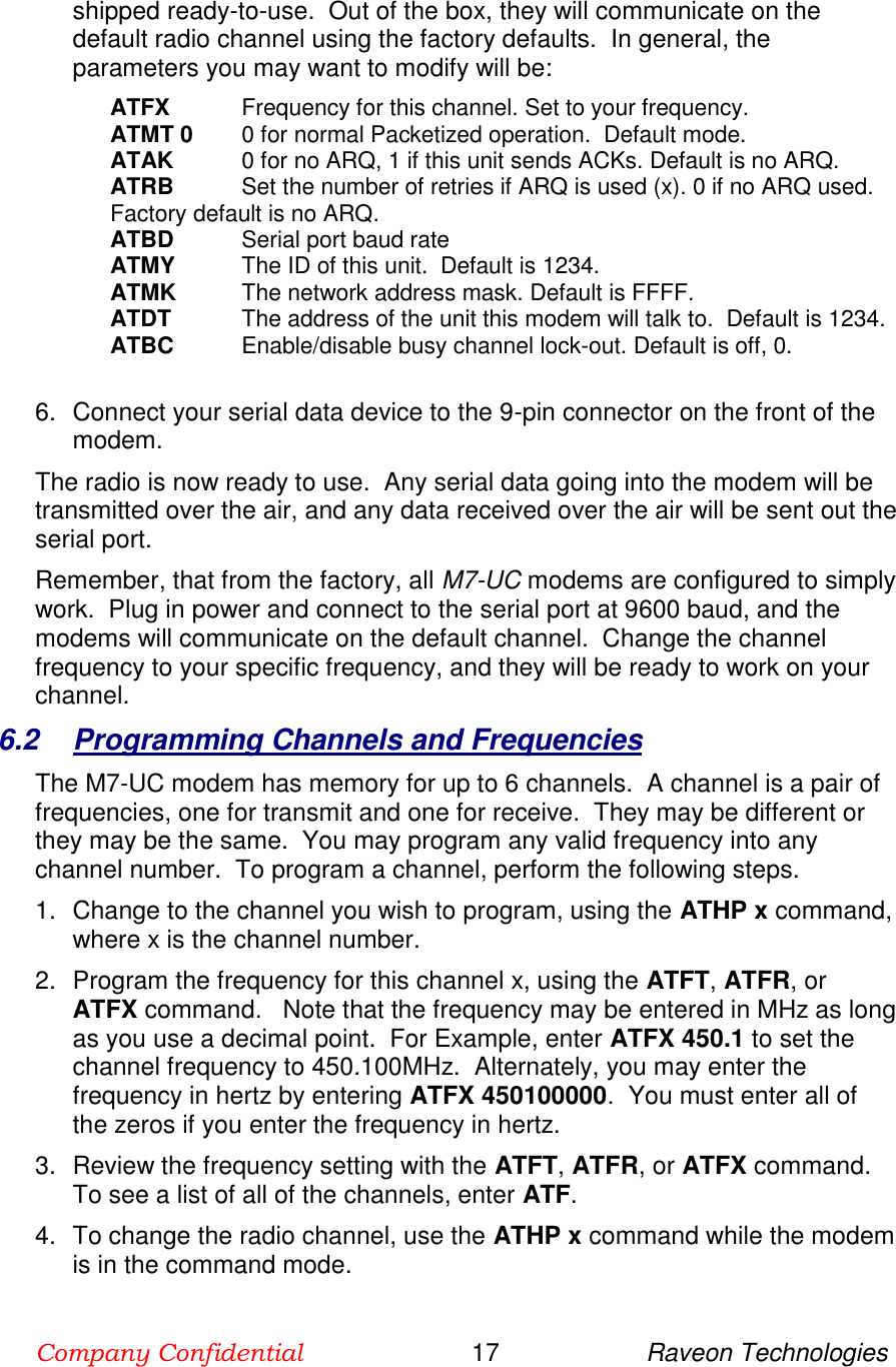
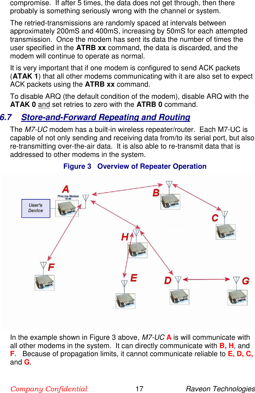
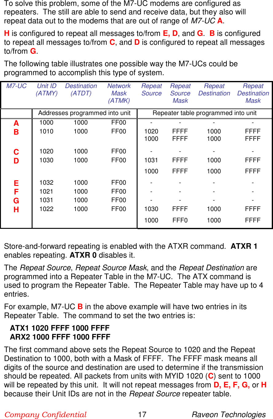
![Company Confidential 18 Raveon Technologies 5 Serial Port Commands 5.1 Overview Only trained radio technicians are allowed to modify the settings in this product. The serial port the RF modem is used to send and receive data over the air, as well as to configure the RF modem. In normal operation, the user sends data into the TxD pin of the user port, and this data is transmitted over the air. Received data from another RF modem is output to the user via the RxD pin of the user port. This is the default operating condition of the RF modem. No special characters, hardware control lines, or timing is required to operate the M7-UC modem. There is also a “Command Mode” used to program and configure the M7-UC. In the Command Mode, the M7-UC modem accepts commands via the serial port TxD pin. The commands can be used to change certain internal parameters of the M7-UC modem as well as to read-out the current configuration and diagnostic statistics. 5.2 Command Mode The M7-UC modem may be put into a “Command Mode”, by entering a sequence of three plus characters (+++). To keep the M7-UC modem from unintentionally entering the Command Mode because of the +++ pattern occurring in a stream of data entering the modem, there must be a pause in the data stream before the +++ as well as a pause after the +++ is sent. If either pause is missing, the modem will not enter the command mode. Using serial communications software such as HypterTerminal, send the 3-character command sequence “+++” while observing times of silence before [BT (Silence Before Sequence) Command] and after [AT (Silence After Sequence) Command] the command characters. The default BT and AT times are 500mS. The default sequence for entering into AT Command Mode: 1. No characters sent for ½ a second. 2. Input three (3) plus characters (“+++”) within ½ of a second. 3. No characters sent for ½ a second. When the M7-UC modem first enters the Command Mode, it sends the phrase “M7-UC” out it serial port, and then an “OK” sequence. The “OK” sequence is a sequence of 4 characters: An “O”, “K”, <CR>, and <LF> characters (<CR> = ASCII 0D, <LF> = ASCII 0A)](https://usermanual.wiki/Raveon-Technologies-orporated/M7-UC/User-Guide-2881339-Page-18.png)


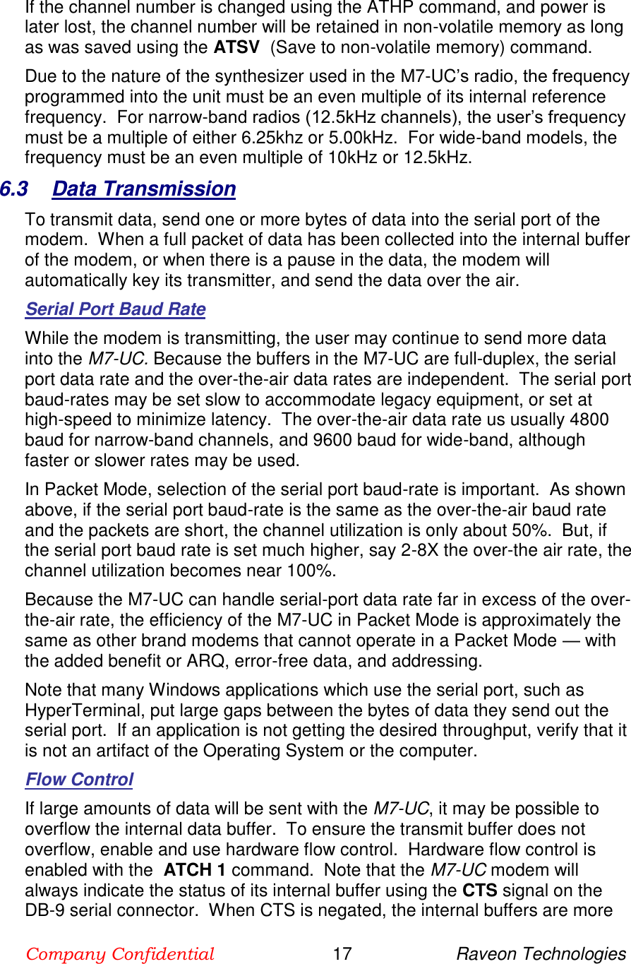
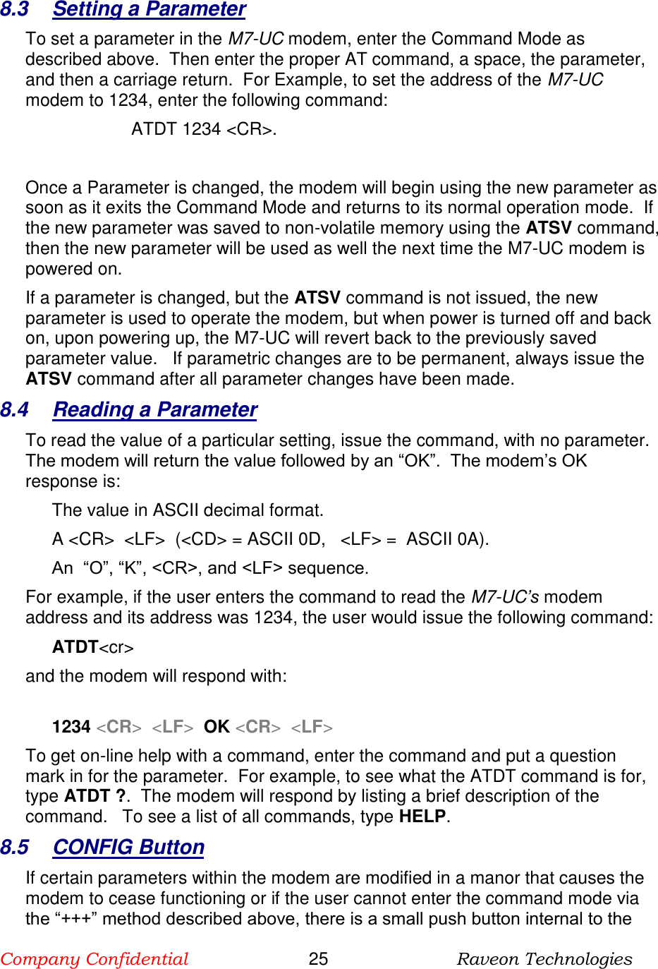
![Company Confidential 25 Raveon Technologies 8 Serial Port Commands 8.1 Overview Only trained radio technicians are allowed to modify the settings in this product. The serial port the RF modem is used to send and receive data over the air, as well as to configure the RF modem. In normal operation, the user sends data into the TxD pin of the user port, and this data is transmitted over the air. Received data from another RF modem is output to the user via the RxD pin of the user port. This is the default operating condition of the RF modem. No special characters, hardware control lines, or timing is required to operate the M7-UC modem. There is also a “Command Mode” used to program and configure the M7-UC. In the Command Mode, the M7-UC modem accepts commands via the serial port TxD pin. The commands can be used to change certain internal parameters of the M7-UC modem as well as to read-out the current configuration and diagnostic statistics. 8.2 Command Mode The M7-UC modem may be put into a “Command Mode”, by entering a sequence of three plus characters (+++). To keep the M7-UC modem from unintentionally entering the Command Mode because of the +++ pattern occurring in a stream of data entering the modem, there must be a pause in the data stream before the +++ as well as a pause after the +++ is sent. If either pause is missing, the modem will not enter the command mode. Using serial communications software such as HypterTerminal, send the 3-character command sequence “+++” while observing times of silence before [BT (Silence Before Sequence) Command] and after [AT (Silence After Sequence) Command] the command characters. The default BT and AT times are 500mS. The default sequence for entering into AT Command Mode: 1. No characters sent for ½ a second. 2. Input three (3) plus characters (“+++”) within ½ of a second. 3. No characters sent for ½ a second. When the M7-UC modem first enters the Command Mode, it sends the phrase “M7-UC” out it serial port, and then an “OK” sequence. The “OK” sequence is a sequence of 4 characters: An “O”, “K”, <CR>, and <LF> characters (<CR> = ASCII 0D, <LF> = ASCII 0A)](https://usermanual.wiki/Raveon-Technologies-orporated/M7-UC/User-Guide-2881339-Page-39.png)


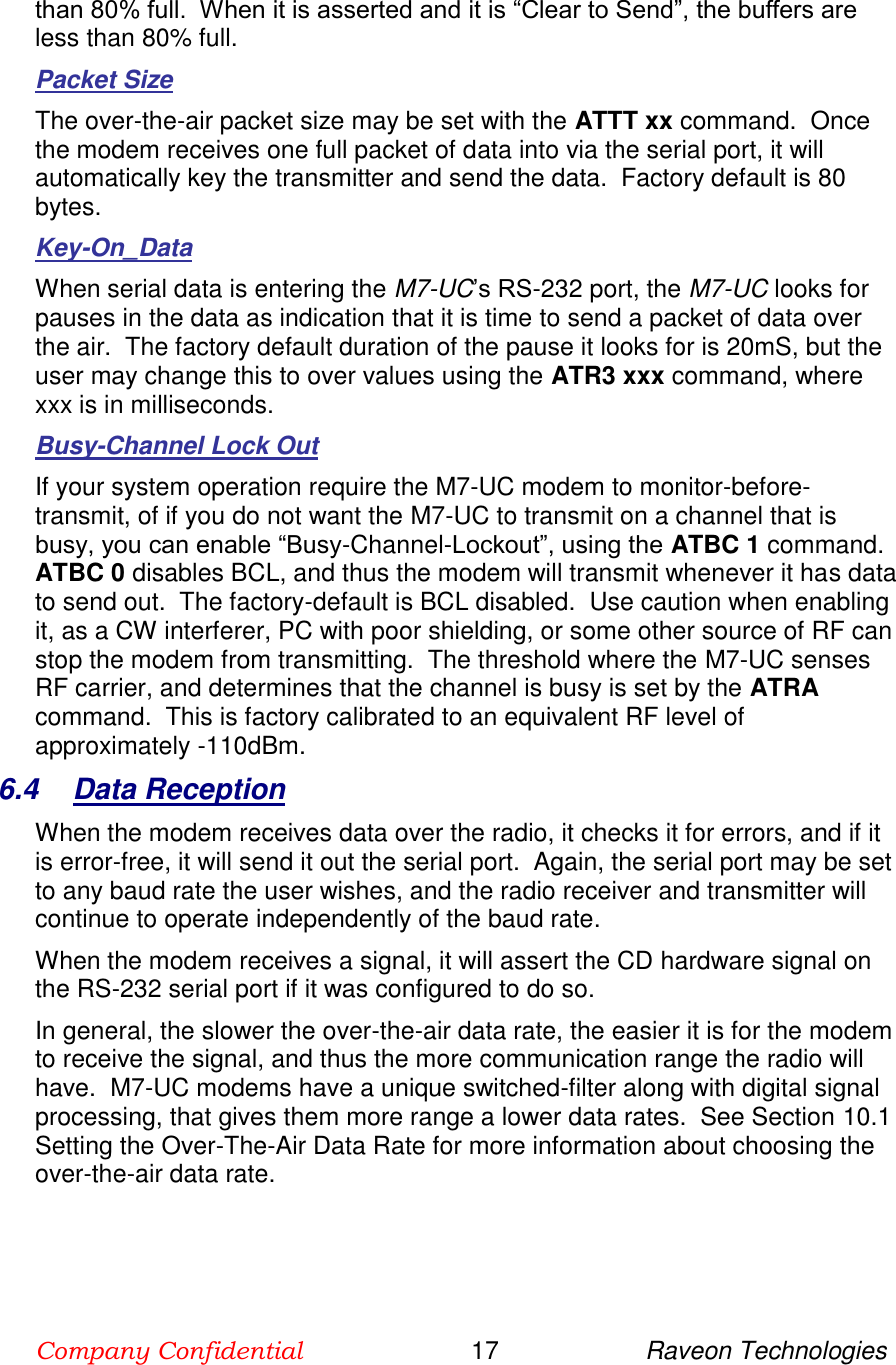
![Company Confidential 56 Raveon Technologies 11.6 ATST3 Command The ATST3 command, will return the time and date the firmware in the M7-UC was compiled. 11.7 ATST4 Command The ATST4 command will return internal timers that tell how long the modem has been powered up and running. All of these timers restart a 0 upon power up. Run time: Years: nnn (number of years running) Days : nnn (number of days running, resets to 0 after one year) Hours: nnn (number of hours running, resets to 0 after 23 hours, 59 minutes, 59 seconds) Min: nnn (number of minutes running, resets to 0 after 59 minutes, 59 seconds) Sec: nnn (number of seconds running, resets to 0 after 59 seconds) Uptime:nnn (number of seconds running. Does not reset. OK 11.8 AutoStatus The auto-status feature of the M7-UC enables it to automatically transmit a packet of status information. By default, this feature is disabled. To enable the Auto Status feature, use the ATAS xxx command, where xxx is the status interval in minutes. The interval may be between 1minute an 65000 minutes (45 days). The general format of the message that the modem will send is: [an ASCII STX character, 02] BEGIN STATUS ATMY=1234 ATVR=D1 ATDT=1234 ATVB=12300 UPTIME=120 OSERR=0 PRX=1295 PTX=7933 [an ASCII ETX character, 03] The first character is a Start of Text character. This is followed by the phrase “BEGIN STATUS”. Each line in the status transmission is terminated with an ASCII carriage return (0D) and line feed (0A). As new features are added to the M7-UC, there may be new status lines added, but all M7-UC modems with Revsion D or higher firmware support at a minimum, the above shown status parameters. The status transmission will end with an ASCII 0 character, the End of Text character. The parameters passed in the status message are: ATMY The ID of the modem sending the status. ATVR The firmware version in the modem ATDT The ID the modem is programmed to send data to. ATVB DC voltage, in millivolts of the DC input to the modem. UPTIME Number of seconds since this modem has turned on. OSERR The number of Operatin System Errors. Normally this is 0.](https://usermanual.wiki/Raveon-Technologies-orporated/M7-UC/User-Guide-2881339-Page-56.png)