RapidWave RWIRL54BR1 High Rate Wireless Bridge User Manual Unpacking

RapidWave Inc. High Rate Wireless Bridge Unpacking

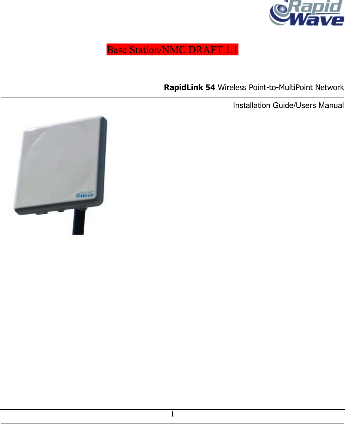
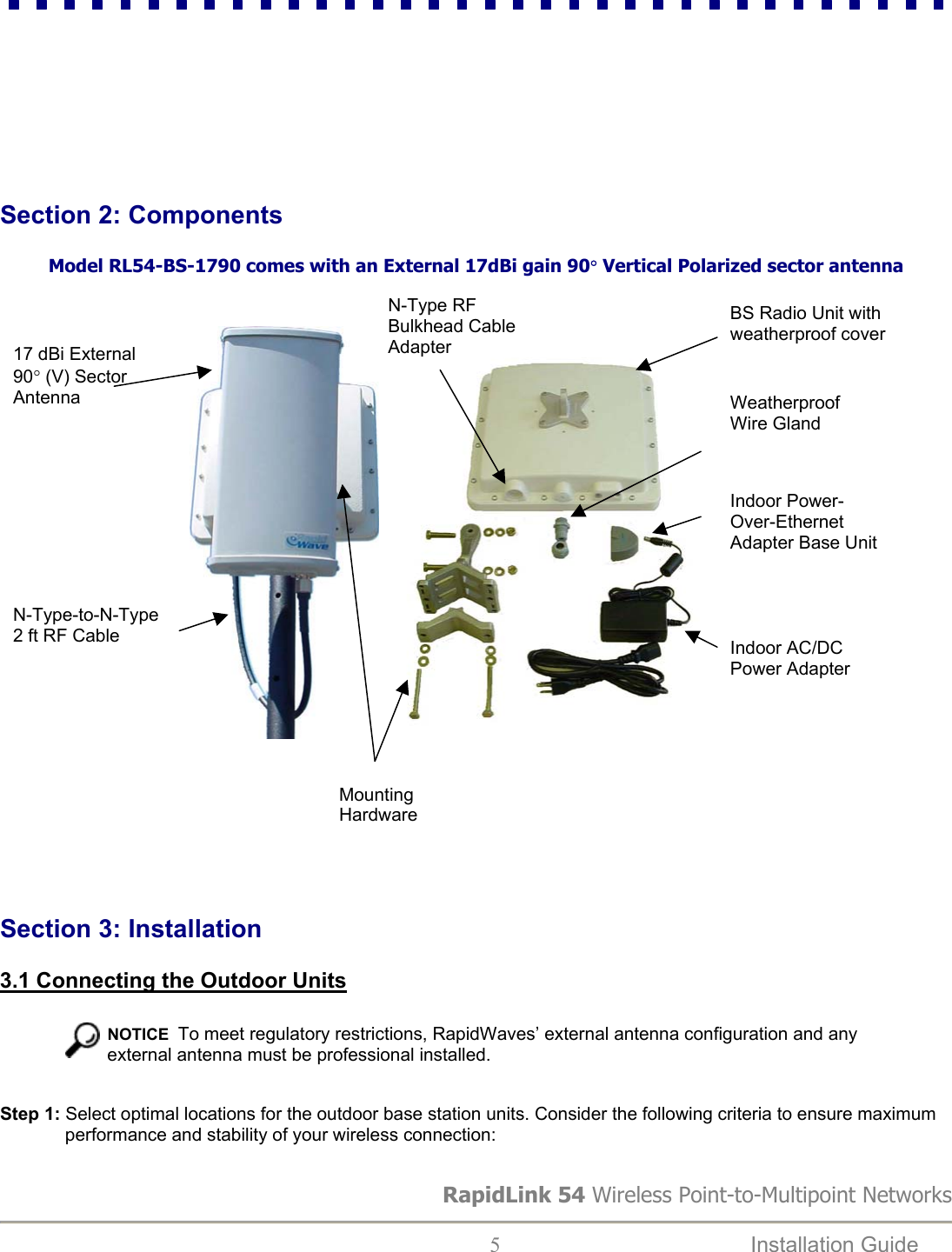
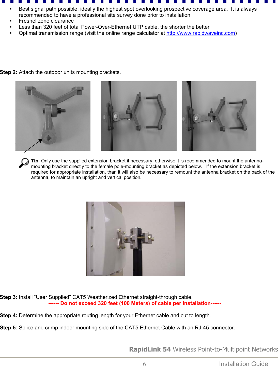
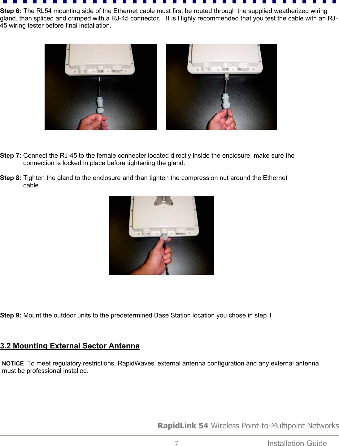
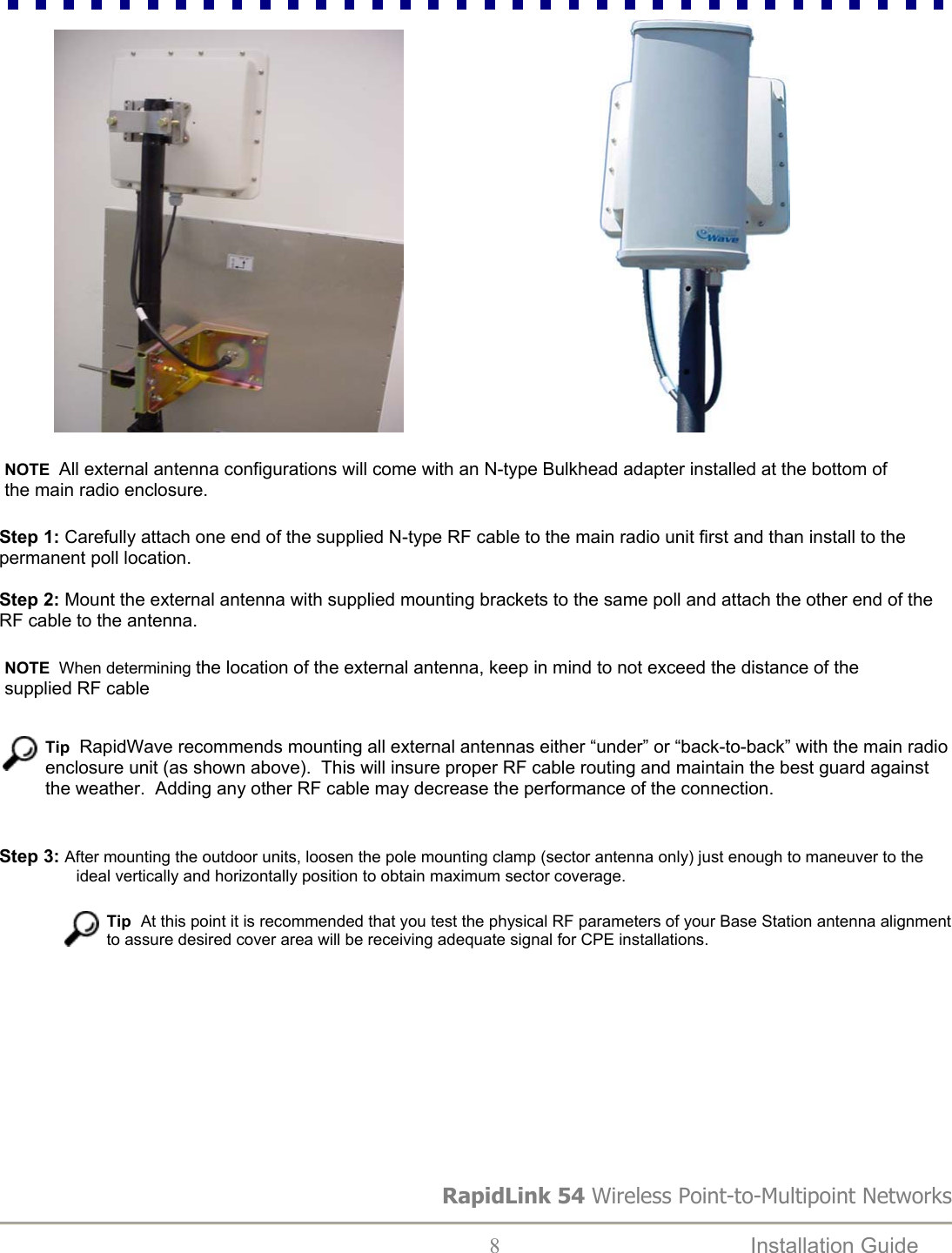
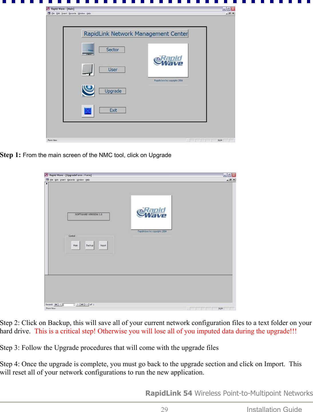
Base Unit User Manual

      Base Station/NMC DRAFT 1.1                                                                           RapidLink 54 Wireless Point-to-MultiPoint Network  Installation Guide/Users Manual                   1
 Rev. 0.1 10-6-04 RapidLink is a trademark of RapidWave, Inc. Other trademarks or brand names mentioned herein are trademarks or registered trademarks of their respective companies.  RapidWave, Inc. 6296 A San Ignacio Ave. San Jose, CA 95119  Telephone: (408) 363-5984 Fax: (408) 363-5972 URL: http://www.rapidwaveinc.com                        Any changes or modifications not expressly approved by the party responsible for compliance could void the user's authority to operate the equipment.   Copyright © RapidWave, Inc. – All Rights Reserved No part of this document may be copied or reproduced in any form or by any means without the prior written consent of RapidWave, Inc.  RapidWave makes no warranties with respect to this documentation and disclaims any implied warranties of merchantability, quality, or fitness for any particular purpose. The information in this document is subject to change without notice. RapidWave reserves the right to make revisions to this publication without obligation to notify any person or entity of any such changes. RapidLink 54 Wireless Point-to-Multipoint Networks  2  Installation Guide
                                              Table of Contents:      1.  For your safety...........................................................................................…..4  2.  Components...........................……………………………...........................…...5 3.  Installation................................……………………………….......……………...5                  3.1 Connecting the Outdoor Units……………………………………..…….5                  3.2 Mounting External Sector Antennas…………………………………….7      3.3 Connecting the Indoor Units (Power-over-Ethernet Injectors)………..9 4.  Basic Base Station Radio Configuration………………………………… …….12                  4.1 Overview of the RapidLink 54 Web Interface…………………………12                  4.2 Setting Basic Network Parameters…………………………………….12 5.  Advanced Configuration Options and Tools……………………………………13                  5.1 Advanced Page…………………………………………………………..14                    5.2 Security………………………………………………………………..…..19                  5.3 Firmware Upgrade………………………………………………………..22 6.  RapidLink 54 PtMP Network Management Center…………………………….23             6.1 Installing RapidLink 54 NMC……………………………………………23             6.2 Adding, Modifying & Deleting Sectors………………………………….23             6.3 Adding, Modifying & Deleting Users/Services…………………………26             6.4 Upgrading Application Files……………………………………………...28 7. Notes………………………………………………………………………………...30 8. Warranty…………………………………………………………………………….31    __________________________________________________________________________                 RapidLink 54 Wireless Point-to-Multipoint Networks  3  Installation Guide
RapidLink 54 Wireless Point-to-Multipoint Networks  4  Installation Guide        Section 1: For Your Safety                    WARNING              Use extreme care when installing equipment or working near power lines.                                                                                        CAUTION          When the unit is in operation, avoid standing directly in         front of the antenna. Strong RF fields are present when         the transmitter is on.                                                   The antenna used for this transmitter must be installed to provide a                                               separation distance of at least 150 cm from all persons.                                                    This Point-to-MultiPoint device and its antenna(s) must not be                                              co-located or operating in conjunction with any other antenna or                                               transmitter.   This equipment has been tested and found to comply with the limits for                                               a Class A digital device, pursuant to part 15 of the FCC Rules. These                                               limits are designed to provide reasonable protection against harmful                                              interference when the equipment is operated in a commercial                                              environment. This equipment generates, uses, and can radiate radio                                              frequency energy and, if not installed and used in accordance with the                                               instruction manual, may cause harmful interference to radio                                              communications. Operation of this equipment in a residential area is                                               likely to cause harmful interference in which case the user will be        required to correct the interference at his own expense.
       Section 2: Components   Model RL54-BS-1790 comes with an External 17dBi gain 90° Vertical Polarized sector antenna   RapidLink 54 Wireless Point-to-Multipoint Networks  5  Installation Guide                                        N-Type RF Bulkhead Cable Adapter BS Radio Unit with weatherproof cover 17 dBi External 90° (V) Sector Antenna  Weatherproof Wire Gland Indoor Power-Over-Ethernet Adapter Base UnitN-Type-to-N-Type 2 ft RF Cable  Indoor AC/DC Power Adapter   Mounting Hardware      Section 3: Installation  3.1 Connecting the Outdoor Units    NOTICE  To meet regulatory restrictions, RapidWaves’ external antenna configuration and any external antenna must be professional installed. Step 1: Select optimal locations for the outdoor base station units. Consider the following criteria to ensure maximum performance and stability of your wireless connection:
  Best signal path possible, ideally the highest spot overlooking prospective coverage area.  It is always recommended to have a professional site survey done prior to installation   Fresnel zone clearance   Less than 320 feet of total Power-Over-Ethernet UTP cable, the shorter the better   Optimal transmission range (visit the online range calculator at http://www.rapidwaveinc.com)      Step 2: Attach the outdoor units mounting brackets.                                                                                                                                                          Tip  Only use the supplied extension bracket if necessary, otherwise it is recommended to mount the antenna-mounting bracket directly to the female pole-mounting bracket as depicted below.   If the extension bracket is required for appropriate installation, than it will also be necessary to remount the antenna bracket on the back of the antenna, to maintain an upright and vertical position.                                                                                          Step 3: Install “User Supplied” CAT5 Weatherized Ethernet straight-through cable.                                   ------ Do not exceed 320 feet (100 Meters) of cable per installation------  Step 4: Determine the appropriate routing length for your Ethernet cable and cut to length.  Step 5: Splice and crimp indoor mounting side of the CAT5 Ethernet Cable with an RJ-45 connector.  RapidLink 54 Wireless Point-to-Multipoint Networks  6  Installation Guide
Step 6: The RL54 mounting side of the Ethernet cable must first be routed through the supplied weatherized wiring gland, than spliced and crimped with a RJ-45 connector.   It is Highly recommended that you test the cable with an RJ-45 wiring tester before final installation. RapidLink 54 Wireless Point-to-Multipoint Networks  7  Installation Guide                                         Step 7: Connect the RJ-45 to the female connecter located directly inside the enclosure, make sure the               connection is locked in place before tightening the gland.  Step 8: Tighten the gland to the enclosure and than tighten the compression nut around the Ethernet                cable                                                                                                                                      Step 9: Mount the outdoor units to the predetermined Base Station location you chose in step 1    3.2 Mounting External Sector Antenna NOTICE  To meet regulatory restrictions, RapidWaves’ external antenna configuration and any external antenna must be professional installed.
                                                      NOTE  All external antenna configurations will come with an N-type Bulkhead adapter installed at the bottom of the main radio enclosure.    Step 1: Carefully attach one end of the supplied N-type RF cable to the main radio unit first and than install to the permanent poll location.     Step 2: Mount the external antenna with supplied mounting brackets to the same poll and attach the other end of the RF cable to the antenna.    NOTE  When determining the location of the external antenna, keep in mind to not exceed the distance of the supplied RF cable    Tip  RapidWave recommends mounting all external antennas either “under” or “back-to-back” with the main radio enclosure unit (as shown above).  This will insure proper RF cable routing and maintain the best guard against the weather.  Adding any other RF cable may decrease the performance of the connection.   Step 3: After mounting the outdoor units, loosen the pole mounting clamp (sector antenna only) just enough to maneuver to the                      ideal vertically and horizontally position to obtain maximum sector coverage.     Tip  At this point it is recommended that you test the physical RF parameters of your Base Station antenna alignment to assure desired cover area will be receiving adequate signal for CPE installations.            RapidLink 54 Wireless Point-to-Multipoint Networks   8  Installation Guide
    Step 4: Secure the outdoor unit’s Ethernet cable (that you attached to the bottom of the outdoor unit) along the length of the pole using tie-wraps, run the cable toward the inside of the building.                                                                Tip  For best results, secure this cable to the pole at least every 10 feet with tie-wraps.   3.3 Connecting the Indoor Units (Power-over-Ethernet Injectors) The indoor unit is the point at which the outdoor units connect with your indoor LAN. More specifically, the indoor unit connects your wireless unit to the network and transmits both data and power to the outdoor unit.   Perform the following steps (1-6) to connect the indoor unit of the wireless outdoor unit. Step 1: Place the indoor unit in an appropriate location that meets the following criteria:    The distance from the outdoor unit to the indoor Power-Over-Ethernet adapter must not exceed the length of your Ethernet cable after attached to the bottom of the outdoor unit  The distance from the indoor unit to the Ethernet network backbone device (e.g., hub or switch) must not exceed 320 ft (100 meters)  The distance from the indoor unit to an available AC outlet must not exceed the length of the supplied power cable  Step 2: Bring the Ethernet cable into to the wiring closet (where the indoor unit is located), and plug the RJ-45 connector into the combined Ethernet/power output port (P + Data Out) on the front panel of the indoor unit.  RapidLink 54 Wireless Point-to-Multipoint Networks  9  Installation Guide
                                                        RapidLink 54 Wireless Point-to-Multipoint Networks  10  Installation Guide     Caution   Connecting any device other than the outdoor unit to the indoor unit may cause permanent hardware damage.  Do not confuse the RJ-45 connector of the outdoor unit’s with that of the Ethernet cable connected to your backbone device.     Step 3: Connect one end of the brick style power adapter cable to the power jack (Power In) on the rear panel of the indoor unit, and plug the other end of the power cable into the AC wall outlet.                                                             Step 4: Check the front panel of the indoor unit to make certain that the power LED is on. If the power LED is not on, confirm that the power cable is securely connected and that your power source is operational.
                                                     Step 5: Plug your Ethernet patch cable into the Ethernet input port (Data In) of the indoor unit and into the data port of your backbone device.                                                      RapidLink 54 Wireless Point-to-Multipoint Networks  11  Installation Guide     Caution   Do not confuse the Ethernet input port with the Ethernet/Power output port. To avoid permanent hardware damage, make certain that you connect your backbone device to the Ethernet input port (not the Ethernet/Power output port).     Step 6: Check the link LED on your backbone device to confirm that it is on.     Congratulations! At this point, you have completed all the hardware related steps necessary toestablish your point-to-multipoint wireless link. However, your wireless link is not yet operational. Thenext section will describe basic software configuration and antenna alignment procedures necessaryto activate the wireless network.
  Section 4: Basic Base Station Radio Configuration   4.1 Overview of the RapidLink 54 PtMP Base Station Web Interface All basic radio configuration management parameters are accessible through an embedded web server interface called the Wireless Link Manager (WLM). Using a web browser, you can easily log into the web server of your wireless unit. From this user-friendly interface, you can communicate with any RapidLink 54 Base Station and perform configuration, management and trouble-shooting tasks for this local radio.   4.2 Setting Basic Base Station Radio Parameters In this section, you will log into the RapidLink 54 WLM for the first time and modify your radios default settings.    NOTICE  You may need to change your computers TCP/IP local area connection setting to an IP range that is compatible with the default IP of the Base Station  Step 1: Load your web browser.  Step 2: Type the factory default IP address: 192.168.1.54 into the address field of your browser and press Enter. This will load the RapidLink 54 WLM.   Step 3: Enter the default (Case Sensitive) Login: admin and Password: rl54 when prompted and click Enter.                                                             Tip  It is strongly recommended that you change the Password and Login as soon as you have completed the basic configuration by clicking on the Security tab.   See section 5.2 under Security for full details on changing password.    RapidLink 54 Wireless Point-to-Multipoint Networks   12  Installation Guide
  Now you will see the RapidWave 54 WLM. Along the top of the page, you will find five tabs that contain all the configuration options available for RapidLink 54 Base Stations. These tabs are: Setup, Advanced, Security, Antenna Align and Upgrade. You will use the Setup page to set network parameters Step 4: Enter a new IP Address for the Base Station (the IP address of each device must be unique)               Write down your new IP Address for future reference in the NOTES section of this Installation Guide.  If the IP is changed and than forgotten, you may need to reset all default values to recover, disrupting service to all users   Step 5: Enter a Subnet Mask (if different than the default value).  Step 6: Enter the current Gateway Address to which you are connected.  Step 7: Enter the Name of your Base Station Sector.  Step 8: Click Apply.  Step 9: To put the changes into effect, click Restart, a dialog box will appear, click OK.  The Base Station will then restart.  Section 5: Advanced Configuration Options and Tools  From radio-related parameters and security algorithms to diagnostic tools and firmware upgrade utilities, the WLM offers numerous options that help you effectively manage the system and achieve the highest performance possible. This section describes RapidLink 54’s advanced configuration options, which you can find in the following categories:  Advanced     Security     Antenna Align     Upgrade Accessing the advanced options is simple. From the RapidLink 54 WLM, simply click on the tab corresponding to the category you need. The following sub-sections will explain how to configure each parameter within these categories.   Tip  While the options differ, each page functions similarly. As you read the next subsections, keep in mind that regardless of the page, any change you make can only go into effect if you click Apply. If you do not click Apply before moving to the next page, your changes will be lost.   Also be advised that certain parameters in the Advanced and Security pages require you to restart the system in order to take effect. In such cases, go back to the setup page and click on Restart. If you know that you will be making more changes, you can complete all other changes, and restart the system later.            RapidLink 54 Wireless Point-to-Multipoint Networks  13  Installation Guide
 5.1 Advanced Page This page allows you to control radio-related parameters, including Transmit Mode, Data Rate, SSID, Channel and Furthest Link Distance.  These parameters must be identical on both sides of all wireless links. Therefore, any change on the Base Station should also be executed for all CPE’s. This sub-section explains the options in each field of the Advanced page.    Tip  Transmit Mode, Data Rate, and Channel settings are interdependent. Data Rate and Channel are always updated according to the Transmit Mode setting. It is therefore recommended that you select the Transmit Mode first and follow the instructions below in the order that they are presented.                                                             Set Transmit Mode:  Simply click the drop-down menu in the Transmit Mode field and select either Turbo or Standard Mode. Data Rate and Channel options will then update according to the new setting.                          RapidLink 54 Wireless Point-to-Multipoint Networks  14  Installation Guide
                                        RapidLink 54 Wireless Point-to-Multipoint Networks  15  Installation Guide     Set Data Rate:  RapidLink 54 supports several possible data rates ranging from 6 to 108 Mbps. The highest transmission rate is 108 Mbps, with automatic fallback rates that allow the unit to operate in the most efficient manner. By default, the system automatically switches between these rates to maximize coverage. However, you may wish to select a fixed Data Rate based on your specific objectives or needs.  Step 1: To adjust this parameter, click the drop-down menu in the Data Rate field and select the desired rate.
                       RapidLink 54 Wireless Point-to-Multipoint Networks  16  Installation Guide     Note   The default setting, Auto, is recommended.    Auto: When the Data Rate is set to Auto, the Base Station will follow an algorithm to determine the highest bit rate possible for communication with all of the CPE’s on the network.     Fixed Bit Rate: The Auto setting is disabled by selecting a specific bit rate to be used for the wireless link.   This would be appropriate when operating in a well-understood environment, and when full rate operation is not possible.  If you choose to set a fixed rate It is recommended that you start with the lowest bit rate, working your way up to the highest achievable data rate.    Step 2: The Antenna Align section should be used to check signal strength and help determine the furthest regions of your sector coverage.  This is a good “Site Survey” tool to help outline your sectors boundaries and “dead spots” prior to the deployment of CPE’s. Be advised that different data rates have different sensitivities, which will impact range.  Once multiple CPE’s have been installed within the same Base Station sector, this tool will no longer be functional, as you will have no way to determine which CPE on the network is providing which signal strength.                              Enter SSID:   The SSID is a service set identifier that uniquely describes your Base Stations sector and all of the CPE’s that will receive signal from this Base Station. Always use the same SSID for all CPE’s in the covered sector.
                               Set Channel:  Channels are used to set the center frequency used to transmit data over the wireless link. You can avoid active interference by switching channels if you suspect interferers operating on the same frequency. Available channels shown in the drop-down menu are based on local regulatory requirements.   To set the Channel:  Click the drop-down menu in the Channel field and select the desired frequency.   Five channels are available in Transmit Mode Standard   Two channels are available in Transmit Mode Turbo      Note    Always set all CPE’s to the same channel as the host Base Station                RapidLink 54 Wireless Point-to-Multipoint Networks  17  Installation Guide
                                  Tip  If active interference is not an issue, it is recommended that you choose the default Channel (lowest frequency) in order to maximize range.     Set Furthest Link Distance:  Entering the correct Link Distance maximizes performance for all users by ensuring the system is ideally tuned to the distance between the Base Station and the furthest CPE within the sector. You can change this anytime by clicking the drop-down Link Distance menu and selecting the desired setting as new further CPE’s are introduced to the network.    RapidLink 54 Wireless Point-to-Multipoint Networks  18  Installation Guide
                                              5.2 Security   This section describes the parameters available through the Security menu. RapidLink 54 provides two forms of security, access control and privacy. Access control is achieved by MAC address authentication, which allows only known devices to associate with the Base Station and establish a wireless connection.  Another component of access control is the password protected user interface, which can be configured on the Security page. Privacy is accomplished by enabling encryption that prevents rogue stations or wireless sniffers from decoding any captured data. RapidLink 54 provides 128-bit WEP encryption option on the Security page.     Changing your Password  We recommend that you change your Login and Password from the factory default setting to authenticate the identity of the RapidLink 54 administrator and ensure that no unauthorized users gain access to the WLM.   To change your Login and Password, type a new Login name (16 characters maximum). Next, enter a new Password, (16 characters maximum) and enter it again to confirm.    Tip  Create passwords according to the following guidelines: Do Not   Share passwords with unauthorized users    Use personal information easily obtained, such as your actual first or last name, system name, etc.    Use words commonly used as passwords   Use dictionary words or names Do   Base passwords on non-dictionary words, combined with obscure character substitutions   Use the maximum number of characters  RapidLink 54 Wireless Point-to-Multipoint Networks  19  Installation Guide
  Change passwords regularly RapidLink 54 Wireless Point-to-Multipoint Networks  20  Installation Guide                                                                                   Privacy  You can enhance link privacy by setting the Encryption Mode to WEP-128 and entering a valid encryption key. You have the option of either creating keys manually or having the system generate a key for you automatically.   By default, the Encryption Mode is Off. If you wish to increase link privacy, perform the following steps for the Base Station, then repeat these steps for all CPE’s.   Step 1: If you wish to enable encryption, select WEP-128.    Step 2: Click the Key Generation drop-down menu and select either Manual or Automated. If you select Manual, you are required to manually enter each key as described below. If you prefer, you can select Automated, and the system automatically generates four distinct keys based on a passphrase that you enter.   Step 3: Generate at least one valid encryption key. The steps are as follows:    If the Key Generation field is set to Manual, enter keys directly into the fields.  Each key must be composed of 32 hexadecimal characters in the range of A-F and 0-9.   If Key Generation is set to Automated, the Passphrase field and Generate button are enabled. a. Type a Passphrase (no more than 32 characters) that you can easily memorize.  b.  Click Generate, and a one-way hash algorithm will be applied to hash the Passphrase using the specified character encoding and copy the results into the encryption key field.   Note The passphrase is not exchanged over the air. It is as secure as a manually generated key, but easier to remember.
RapidLink 54 Wireless Point-to-Multipoint Networks  21  Installation Guide    CPE / Home Network Security  By the nature of this wireless network, all CPE’s located on the same Base Station will be able to access one another, opening up a potential security problem.  Depending on your network deployment, it is highly recommended that you install or recommend to CPE subscribers to install a firewall inline with their home network deployment.  Please see the basic network configuration below.   Note Telnet and CPE Web interface access is all password protected, so system administrators will have total control and access for updates and maintenance of the PtMP networks, dictating all individual CPE subscribers access as well, without the ability to intrude on any private home networks.
 5.3 Firmware Upgrade  Periodically, RapidWave, Inc. will release firmware updates that enhance various aspects of RapidLink 54 firmware. After registering on http://www.rapidwaveinc.com, you will have access to all the firmware upgrades available. If you have questions about upgrading your firmware, please contact RapidWave’s support team.   The steps involved in performing a firmware upgrade are as follows:  Step 1: Obtain firmware image from RapidWave and save it to a directory on your computer or network drive.  Step 2: Start an FTP Server on your network computer.  Configure an entry for the user name “rapidwave”, with the password “rapidwave”.  The home directory for the “rapidwave” user should be set to the directory where the firmware image is stored.   Step 3: Login to the Base Station WLM Web interface  Step 4: From the RapidLink 54 WLM browser interface select Upgrade.  Step 5: Specify your FTP Server address in the space provided.  Step 6: Click browse to open the Windows browse file dialog.                            Step 7: Click Upgrade to upload the image to the Base Station.  Step 8: Click OK when you see the pop-up with a warning and OK/Cancel options.                           Step 9: When you have successfully loaded the new firmware, the system must be restarted.  Step 10: Repeat steps 2-9 for the all CPE’s as they will utilize the same upgrade image.                 RapidLink 54 Wireless Point-to-Multipoint Networks  22  Installation Guide     Tip  For greatest interoperability, upload the same firmware image or revision for the Base Stations and all CPE’s.   Depending on CPE deployment, you will need to make sure to notify all users to the upgrade.  Make sure that the firmware revisions match on both sides.
RapidLink 54 Wireless Point-to-Multipoint Networks  23  Installation Guide    Section 6: RapidLink 54 PtMP Network Management Center    NMC Introduction  In this section we will walk through the RapidLink proprietary and dynamic, Network Management Center (NMC).  This easy-to-use and user-friendly Access based management center will be your network manager’s tool for adding, deleting and maintaining symmetrical bandwidth allocation for all users and sectors on your new RapidLink 54 PtMP network.  The NMC application can run from any location on the wireless network, you are not tied to any single location to have the ability to administer users or sectors.    6.1 Installing the RapidLink 54 NMC  Note This application requires Microsoft Access to run, and will require the installing system to have a c:\ directory.  If your system does not have a c:\ directory, or Microsoft Access do not attempt to install this application.   Step 1: Check System requirements in note above  Step 2: Insert supplied CD “RapidLink Installation Disc” into system  Step 3: Click on RapidLinkNMC folder  Step 4: Click on Setup.exe  Step 5: Follow on screen installation setup (this application will automatically install in c:\ directory)  Step 6: Once setup is complete, go to your computer, click on c:\, than click on the RapidLink NMC folder and than select the RapidLinkNMC to start the application. (this would be a good time to create a shortcut to your desktop)           6.2 Adding, Modifying & Deleting Sectors   Note You must add Sectors before you can start populating Users/CPE’s
                                                                RapidLink 54 Wireless Point-to-Multipoint Networks  24  Installation Guide
Adding Sectors   Note Any addition, modification or deletion of a sector Mac or IP addresses will not dynamically update the actual Base Station, These changes will need to be done using the Web interface in section 4.  This section of the NMC provides a centralized database to direct CPE updates as well as allowing for CPE to Sector authentication. RapidLink 54 Wireless Point-to-Multipoint Networks  25  Installation Guide      Tip First you should determine an appropriate sector Location/ID naming convection for your network, keep in mind the possibility of sector and user expansion in any given coverage location.  The NMC will also not allow duplicate sector ID’s, even for different locations.   Step 1: Click the Sector button on the opening page  Step 2: Click the Add button on the bottom of the page (this should clear all visible fields if not already clear)  Step 3: Add your Unique sector ID and hit enter, this will tab you down to the next field *required  Step 4: Type in the Wireless Mac Address for this sectors base station AP (you can find this on the back of the base station radio.  It should look like this: WMAC 00:50:c2:39:6x:xx) *required  Step 5: Type (or select from pull down) the Sector Antennas coverage in degrees i.e. 30, 45, 60, 90, 120 or 180 degrees.  Step 6: Enter channel for this sector that was determined from site survey to provide the best coverage with least amount of interference to this sector. i.e. 150, 152, 160…  Step 7: Enter sector antennas Polarization (Vertical or Horizontal), this will need to coincide with all of CPE antenna orientation to be covered by this sector.  Step 8: Enter a location name for this sector, again this is to help identify multiple sectors in one physical location as you may have multiple locations with multiple sectors.  Step 9: Enter the IP address for this sectors Base Station, this was changed in section 4.2 step #2 *required  Step 10: You MUST click Update to send the information to the Base Station, and repeat steps 2 through 10 to add multiple sectors.     Modifying Sectors    Step 1: Click the Sector button on the opening page  Step 2: Click the left or right arrow keys to toggle through records or click the search key to find a record  Step 3: Modify desired fields to be changed   Step 4: Click Update (these changes will be reflected on all CPE’s on the sector)
RapidLink 54 Wireless Point-to-Multipoint Networks  26  Installation Guide     Deleting Sectors   Step 1: Click the Sector button on the opening page  Step 2: Click the left or right arrow keys to toggle through records or click the search key to find a record  Step 3: Confirm that you have the correct Sector (Any sector that has existing CPE’s, can not be deleted, you must remove or move all CPE’s from a sector before you can delete)  Step 4: Click Delete, when prompted click Yes or NO                                               6.3 Adding, Modifying and Deleting Users/Services     Note Any addition, modification or deletion of a Users Mac or IP addresses will not dynamically update the actual CPE. These changes will need to be done using the Web interface in described in the CPE Installation Guide.  This section of the NMC provides a centralized database to direct CPE updates as well as allowing for CPE to Sector authentication.    Tip First you should determine an appropriate User ID naming convection for your network, keep in mind that NMC will not allow for duplicate User ID’s, even for different sectors in different locations.
 Now that you have your sector(s) added to the database, it is time to start adding users and their unique Up and Down steam bandwidth allocation and QoS capabilities.   Adding Users     Step 1: Add Unique User ID *required  Step 2: Complete Last Name  Step 3: Complete First Name  Step 4: Complete Email Address  Step 5: Enter Unique MAC address for the CPE radio (this can be found on the back of the CPE) *required  Step 6: Enter Down Steam Bandwidth allocation value from 0 to 50000 Kbps, if left blank there will be no restriction to bandwidth.  Step 7: Enter Quality of Service functiality by typing On or OFF  Step 8: Select Sector ID that this User with receive signal from. *required  Step 9: Enter UP Steam Bandwidth allocation value from 0 to 50000 Kbps, if left blank there will be no restriction to bandwidth.  Step 10: Enter Users CPE IP address, this will be the IP address you changed in the CPE Installation Guide *required  RapidLink 54 Wireless Point-to-Multipoint Networks Step 11: You MUST click Update to send the information to the CPE, and repeat steps 1 through 11 to add multiple Users.    27  Installation Guide
 Step 12: After all New user information has been added and Updated, you must now click done.  Step 13: Click on sectors from the main screen  Step 14:  Find and open the sector file that the new user will reside and than click Update (this will send the new user information to that sectors Base Station allowing for MAC authentication, rate limiting and QoS functionality)  ****If you have entered multiple users on multiple Sectors, you must go to each sector and update individually for additions or changes to take effect.****   Modifying Users   Step 1: Click the User button on the opening page  Step 2: Click the left or right arrow keys to toggle through records or click the search key to find a User record  Step 3: Modify desired fields to be changed   Step 4: Click Update (this will send the changes to the CPE)  Step 5: Click on sectors from the main screen  Step 6:  Find and open the sector file that the modified user resides and than click Update (this will send the new user information to that sectors Base Station allowing the sector and CPE to be in sync)  ****If you have changed multiple users on multiple Sectors, you must go to each sector and update individually for additions or changes to take effect.****   Deleting Users  Step 1: Click the User button on the opening page  Step 2: Click the left or right arrow keys to toggle through records or click the search key to find a record  Step 3: Confirm that you have the correct User (Caution…any User can be deleted at any time)  Step 4: Click Delete, when prompted click Yes or NO      6.4 Upgrading Application Files  Occasionally RapidWave will release a newer version of the NMC tool, with more features and benefits for all users.  When these releases are announced you will need to obtain the new files and follow these following procedures to upgrade your application files while retaining all configuration files.  RapidLink 54 Wireless Point-to-Multipoint Networks  28  Installation Guide
                             Step 1: From the main screen of the NMC tool, click on Upgrade                               Step 2: Click on Backup, this will save all of your current network configuration files to a text folder on your hard drive.  This is a critical step! Otherwise you will lose all of you imputed data during the upgrade!!!  Step 3: Follow the Upgrade procedures that will come with the upgrade files  Step 4: Once the upgrade is complete, you must go back to the upgrade section and click on Import.  This will reset all of your network configurations to run the new application.  RapidLink 54 Wireless Point-to-Multipoint Networks  29  Installation Guide
  Section 7: Notes                   _______________________________________________________________________________________________________________________________________________________________________________________________________________________________________________________________________________________________________________________________________________________________________________________________________________________________________________________________________________________________________________________________________________________________________________________________________________________________________________________________________________________________________________________________________________________________________________________________________________________________________________________________________________________________________________________________________________________________________________________________________________________________________________________________________________________________________________________________________________________________________________________________________________________________________________________________________________________________________________________________________________________________________________________________________________________________________________________________________________________________________________________________________________________________________________________________________________________________________________________________________________________________________________________________________________            RapidLink 54 Wireless Point-to-Multipoint Networks  30  Installation Guide
RapidLink 54 Wireless Point-to-Multipoint Networks  31  Installation Guide     Section 8: Warranty     RapidWave - Limited Warranty RapidWave Inc. warrants that hardware products will be free from material defects in materials and workmanship for the term of one year from product shipment date. RapidWave Inc. warrants that software media will be free from material defects in materials and workmanship for a period of one year from shipment date.  This Hardware Product warranty covers all RapidWave Inc. parts, accessories, and upgrades sold with your RapidWave Inc. Hardware Product. Unless otherwise set forth, RapidWave Inc. accessories and upgrades purchased and added on to the Hardware Product after the initial Hardware Product purchase assume the warranty deliverables and term of the system into which they are installed.    Limitations NEITHER PARTY WILL BE LIABLE FOR ANY INDIRECT, PUNITIVE, SPECIAL, INCIDENTAL, OR CONSEQUENTIAL DAMAGES IN CONNECTION WITH OR ARISING OUT OF THIS WARRANTY (INCLUDING, WITHOUT LIMITATION, LOSS OF BUSINESS, REVENUE, PROFITS, GOODWILL, USE, DATA, ELECTRONICALLY TRANSMITTED ORDERS, OR OTHER ECONOMIC ADVANTAGE), HOWEVER THEY ARISE, WHETHER IN BREACH OF CONTRACT, BREACH OF WARRANTY OR IN TORT, INCLUDING NEGLIGENCE, AND EVEN IF THAT PARTY HAS PREVIOUSLY BEEN ADVISED OF THE POSSIBILITY OF SUCH DAMAGES. LIABILITY FOR DAMAGES WILL BE LIMITED ADND EXCLUDED, EVEN IF ANY EXCLUSIVE REMEDY PROVIDED FOR FAILS OF ITS ESSENTIAL PURPOSE. SOME STATES AND JURISDICTIONS DO NOT ALLOW LIMITATIONS UPON CONSEQUENTIAL DAMAGES, SO THE ABOVE LIMITATION MAY NOT APPLY TO YOU.   YOUR SOLE AND EXCLUSIVE REMEDY AND RAPIDWAVE INC.'S ENTIRE LIABILITY FOR BREACH OF WARFRANTY WILL BE: (A) THE REPAIR OR, AT RAPIDWAVE INC.'S OPTION AND EXPENSE, REPLACEMENT OF THE DEFECTIVE PRODUCT, OR, IF SUCH REPAIR OR REPLACEMENT IS NOT REASONABLY ACHIEVABLE, THE REFUND OF THE PURCHASE PRICE. ALL EXPRESS OR IMPLIED CONDITIONS, REPRESENTATIONS, AND WARRANTIES, INCLUDING ANY IMPLIED WARRANTY OR CONDITION OF MERCHANTABILITY, SATISFACTORY QUALITY, FITNESS FOR A PARTICULAR PURPOSE AND NON-INFRINGEMENT, ARE HEREBY EXCLUDED TO THE MAXIMUM EXTENT PERMITTED BY LAW. SOME STATES AND JURISDICATIONS DO NOT ALLOW LIMITATIONS UPON IMPLIED WARRANTIES, SO THE ABOVE LIMITATION MAY NOT APPLY TO YOU.                    Founded in July 2002, RapidWave Inc. is a privately held company headquartered in San Jose, California. RapidWave is focused on designing and manufacturing high-performance point-to-point and point-to-multipoint fixed wireless access solutions to address the needs of building communication infrastructures in the emerging economies of the world. RapidWave’s product line offers end-to-end solutions for service providers, government organizations, universities, and businesses to quickly and cost-effectively solve their voice and data communication needs – without wires. For more information, visit the RapidWave web site at http://www.rapidwaveinc.com.

Navigation menu