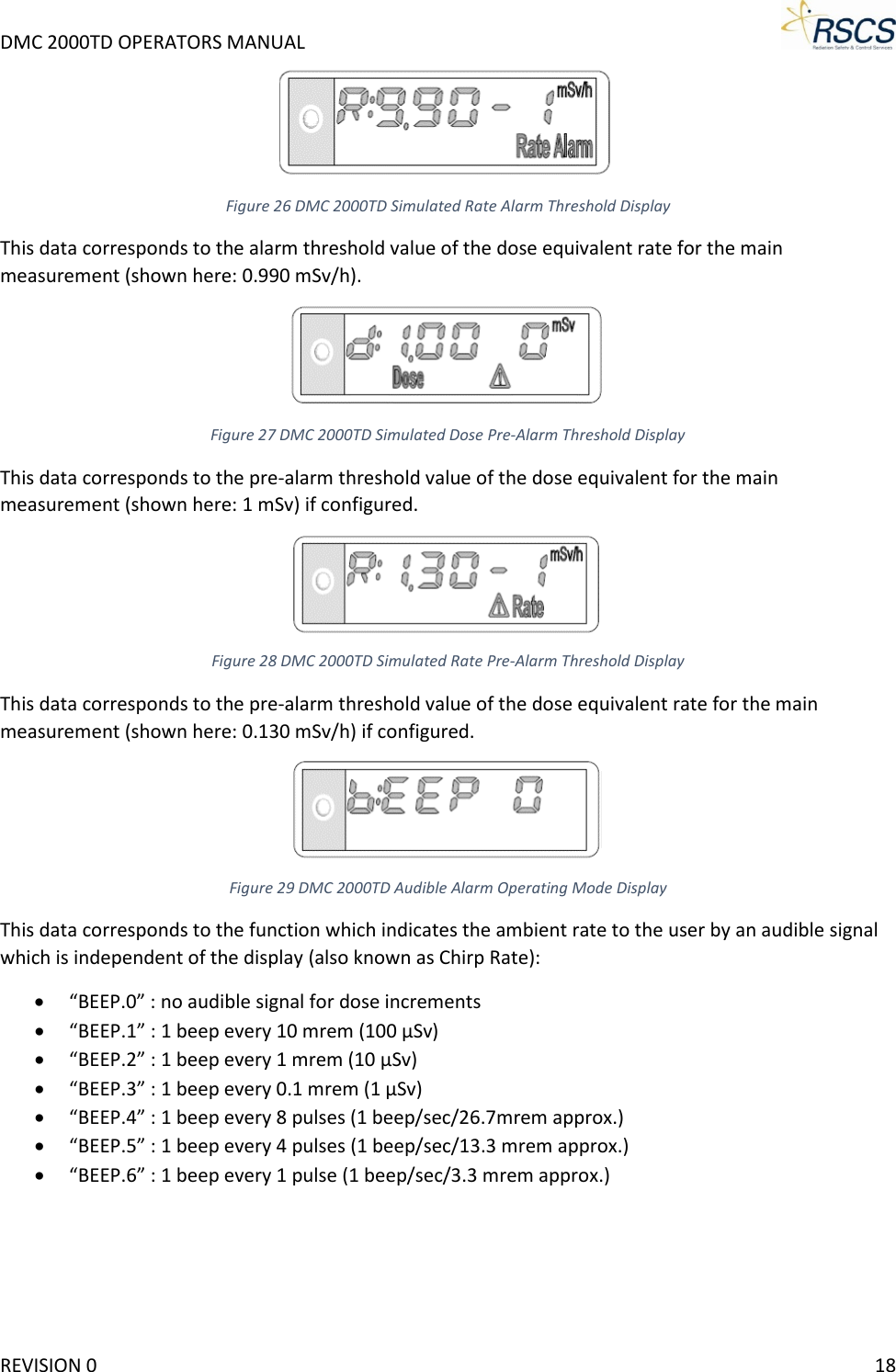
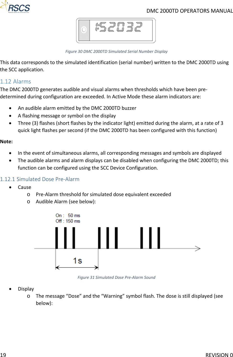
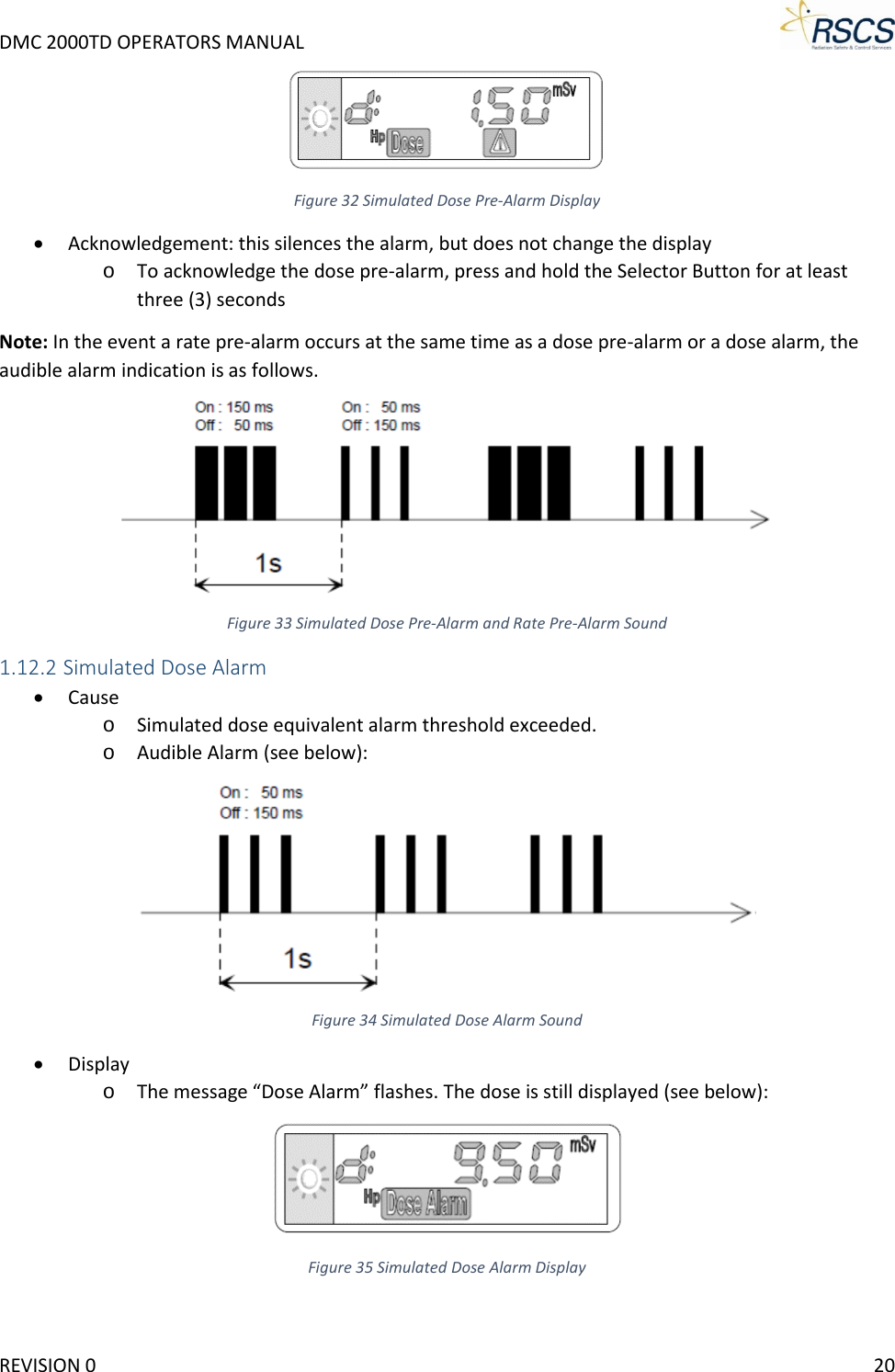
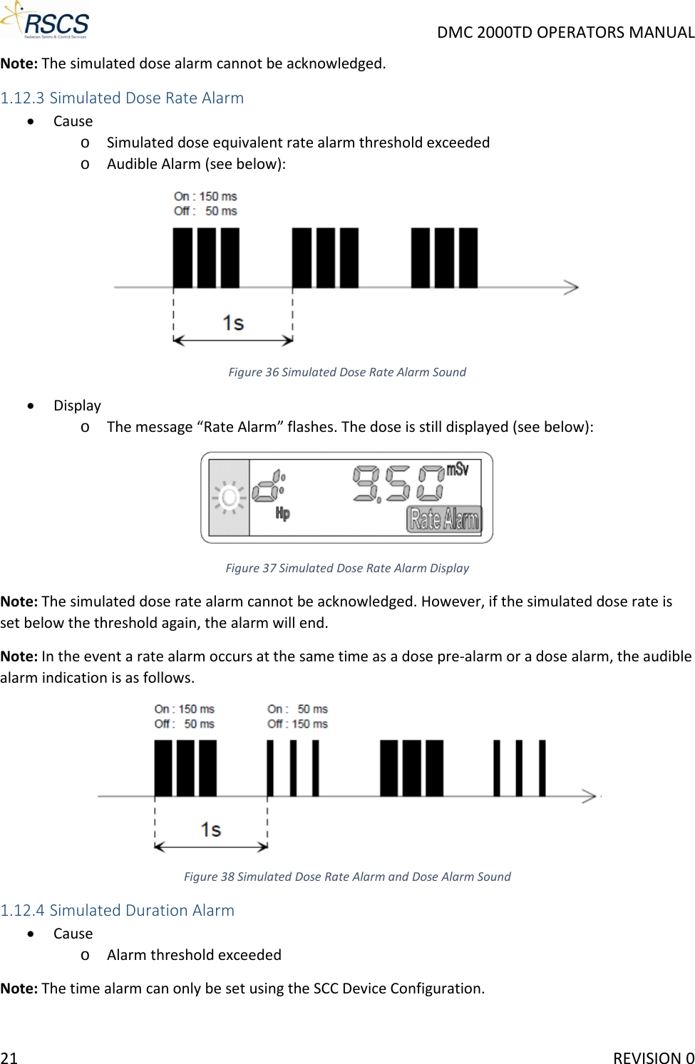
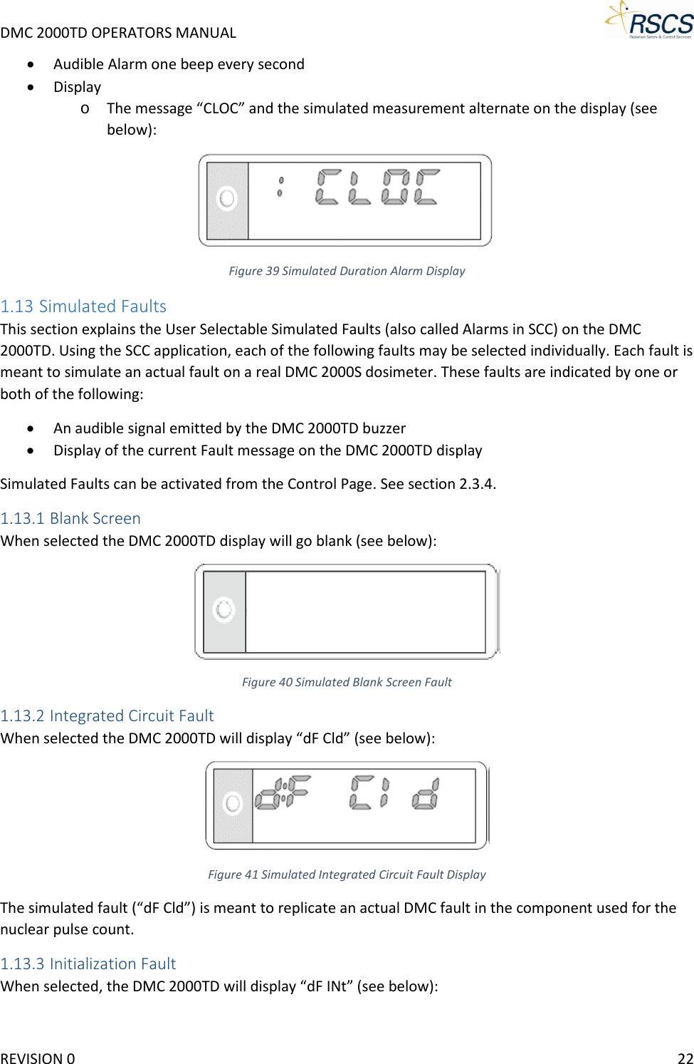
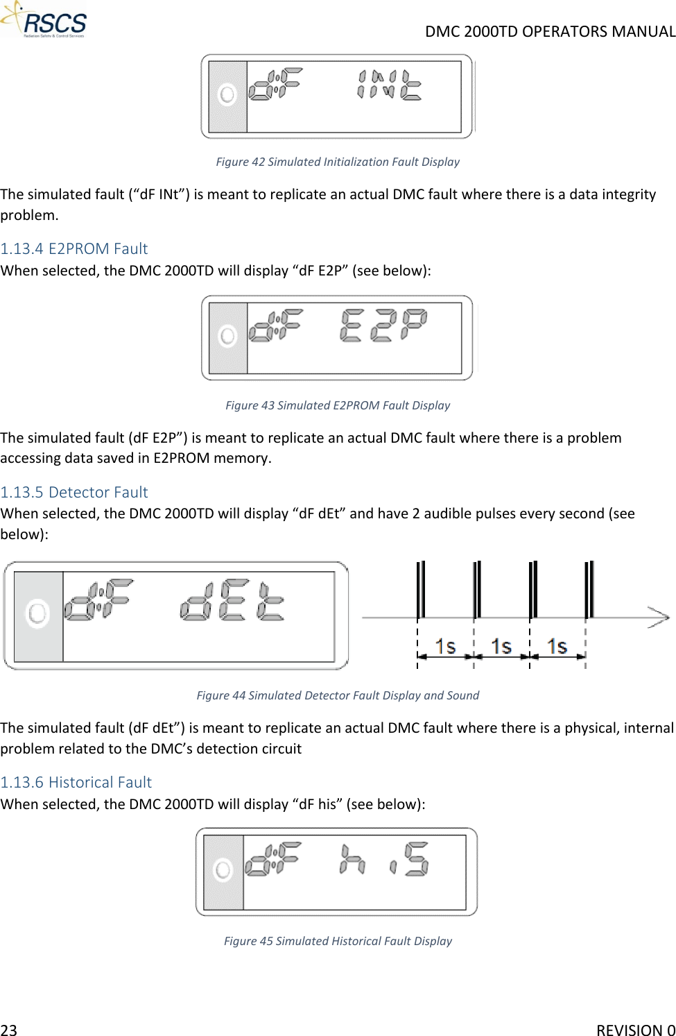
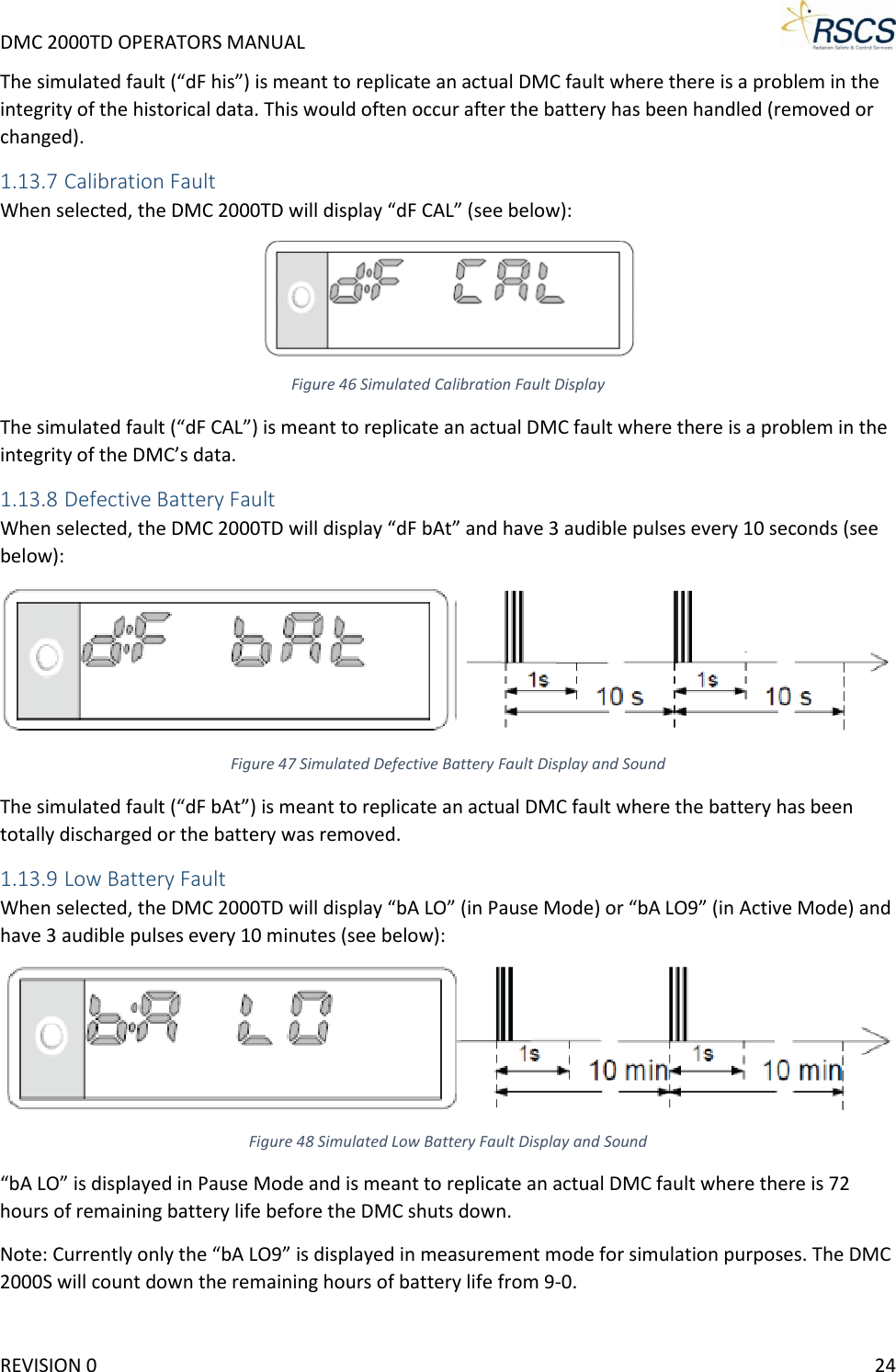
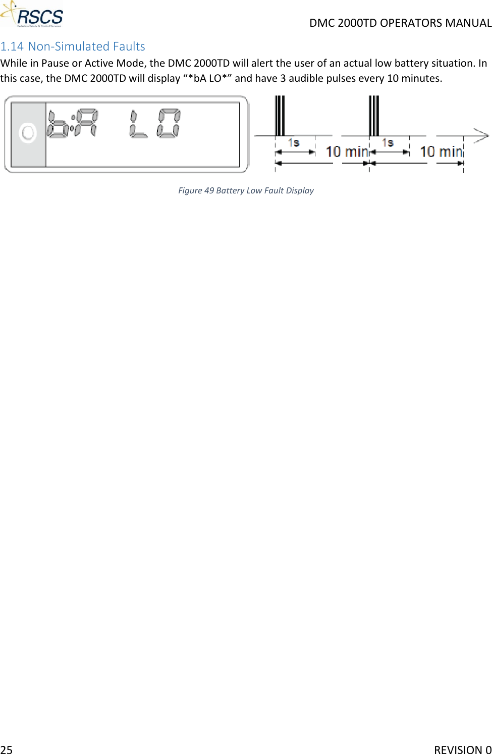
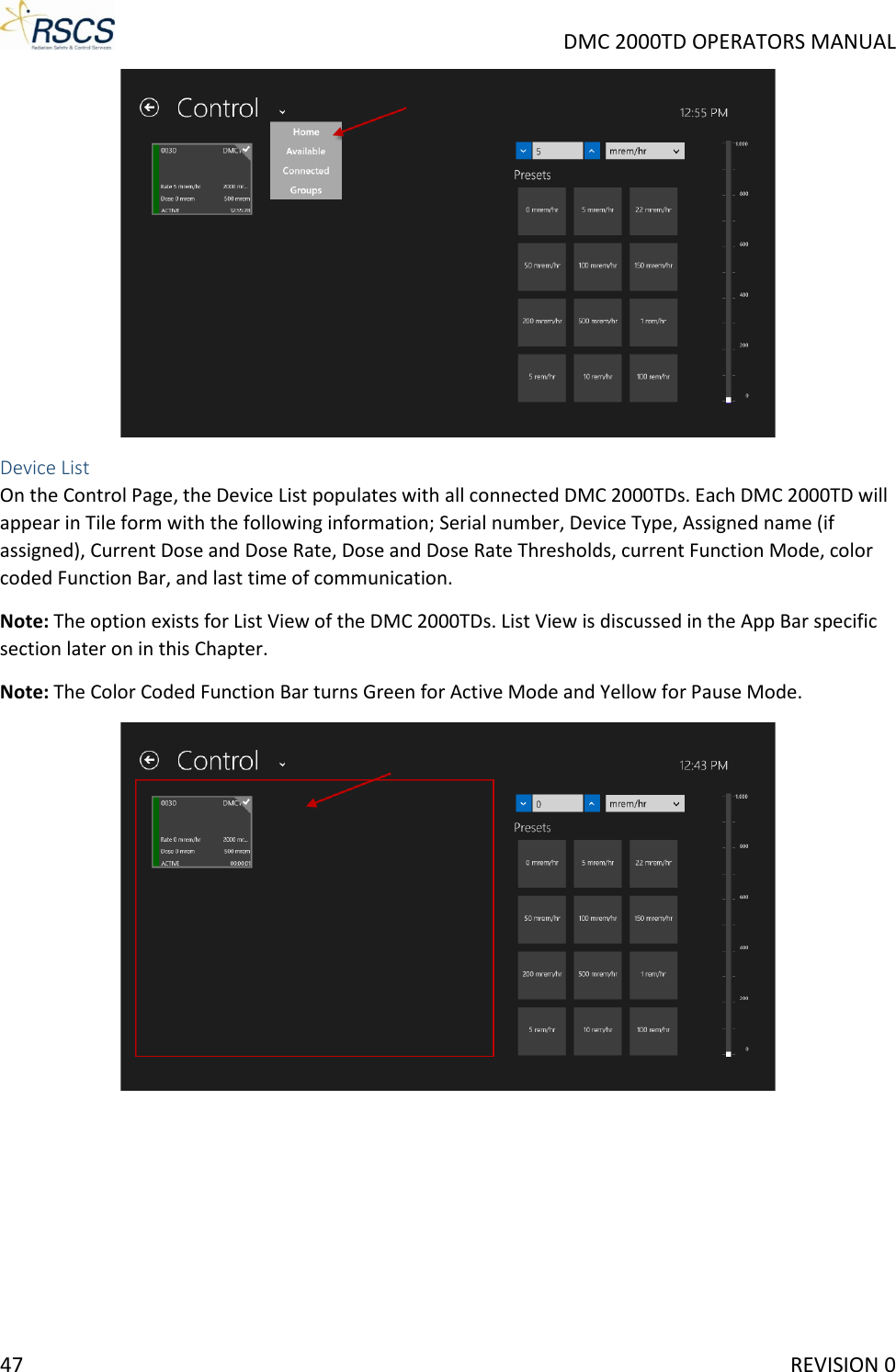
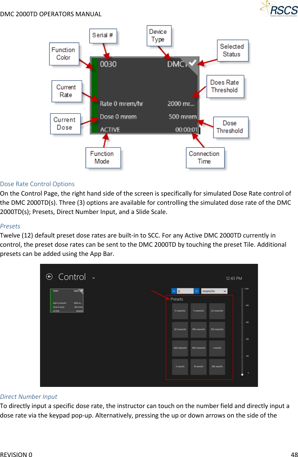
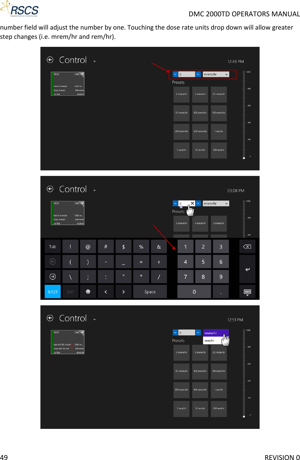
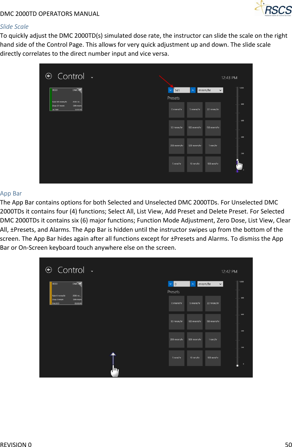
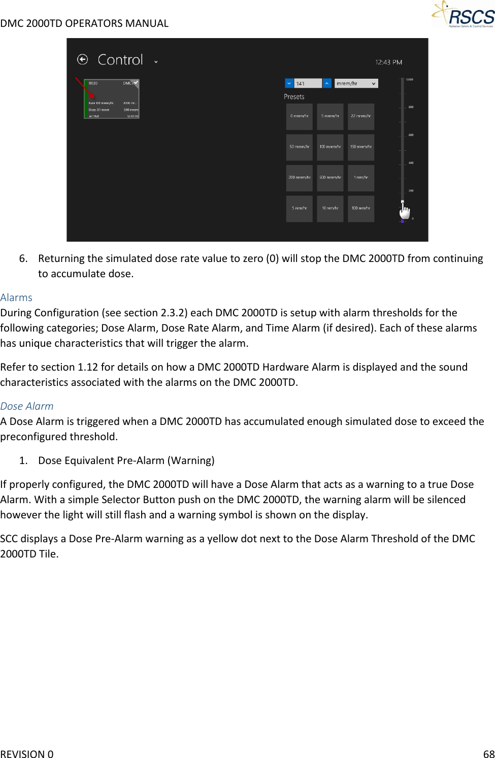
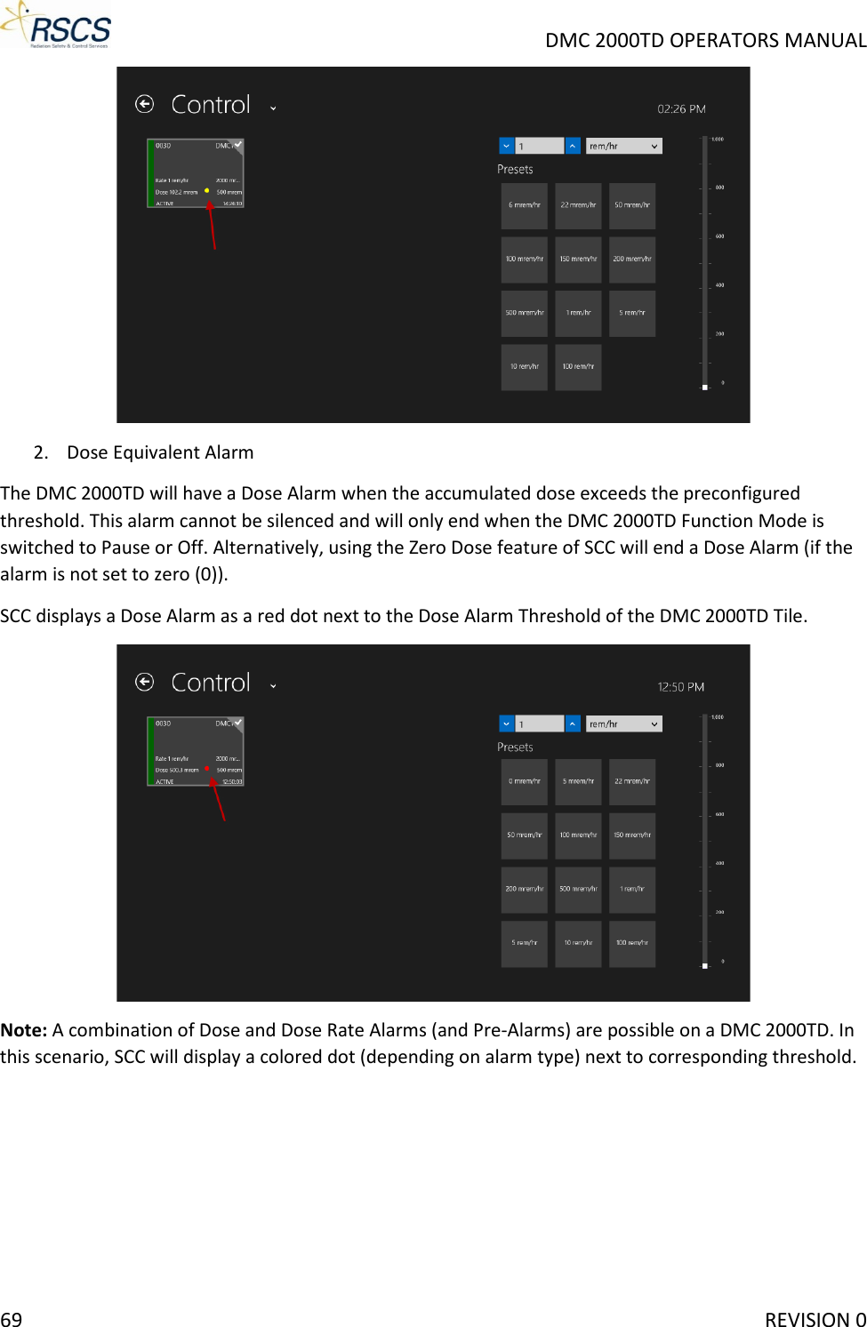
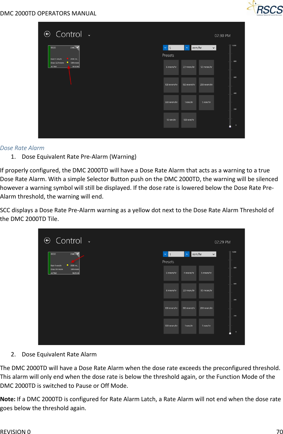
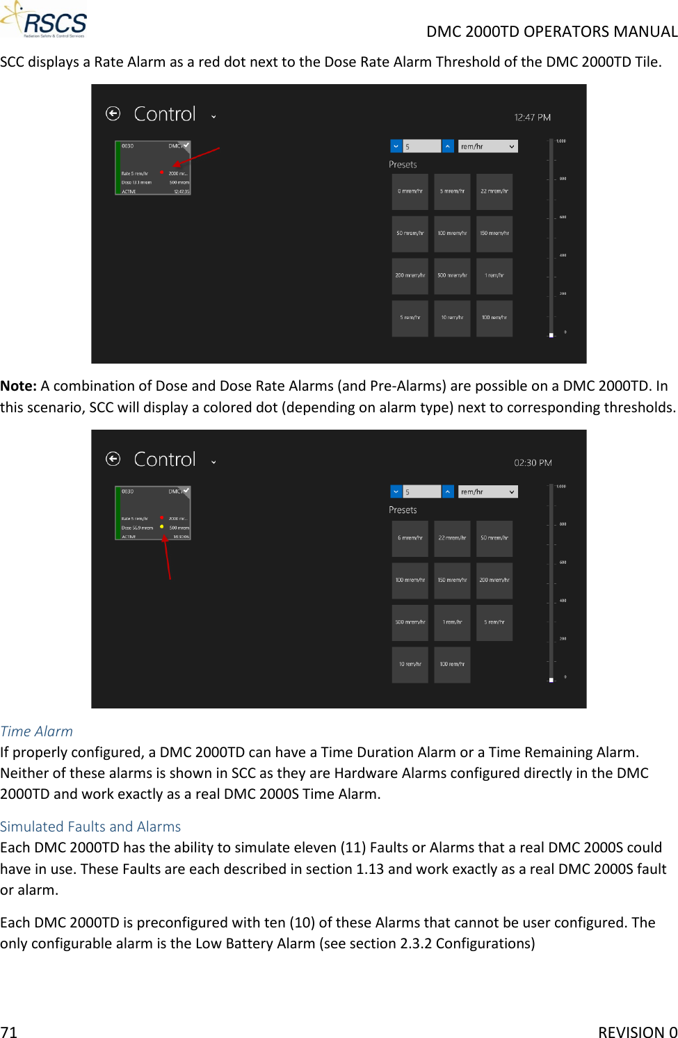
Radiation Safety and Control Services DMCTD2K Simulated Radiation Detection Instrument User Manual Exhibit D Users Manual per 2 1033 b3
Radiation Safety & Control Services, Inc. Simulated Radiation Detection Instrument Exhibit D Users Manual per 2 1033 b3
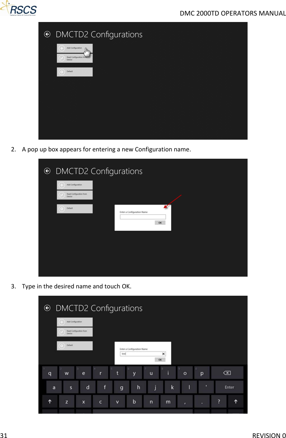
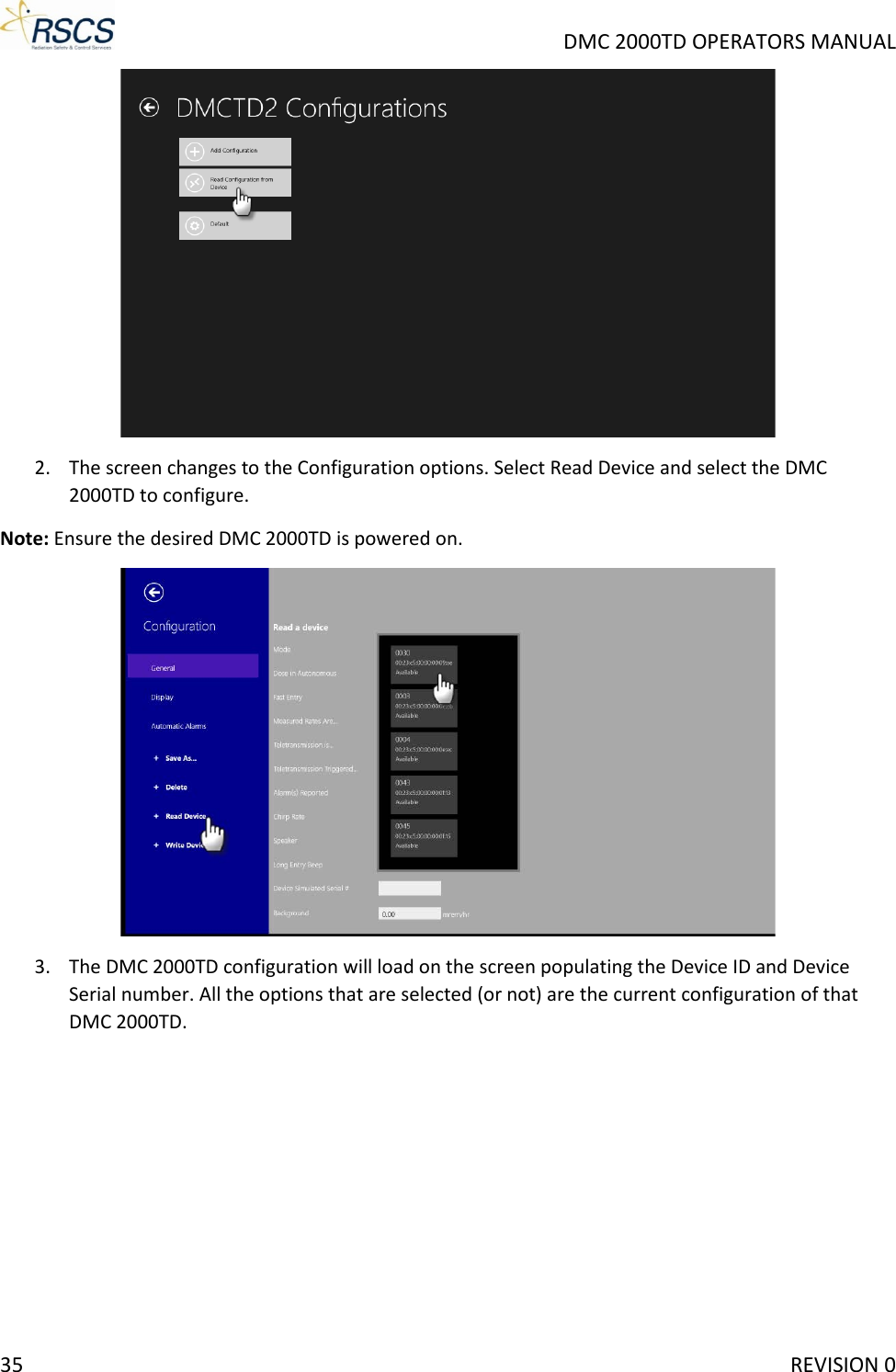
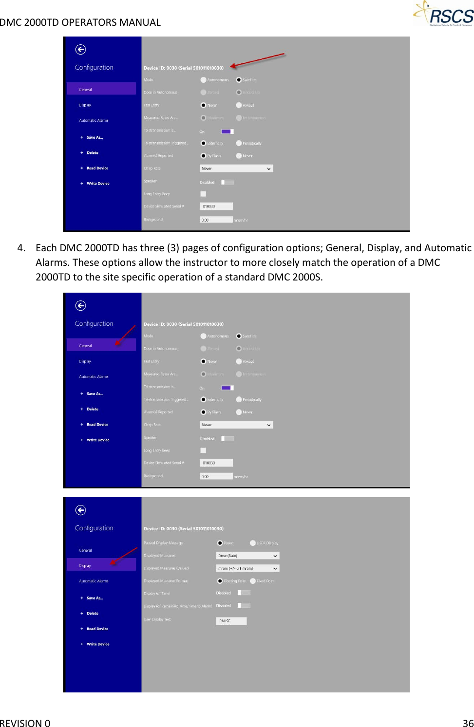
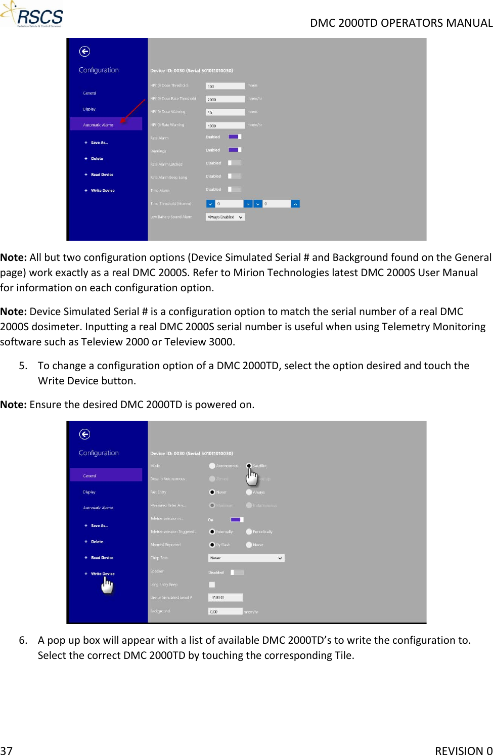
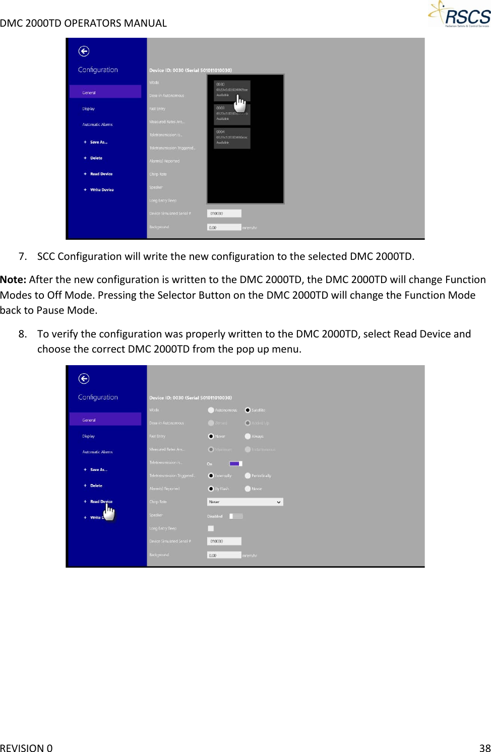
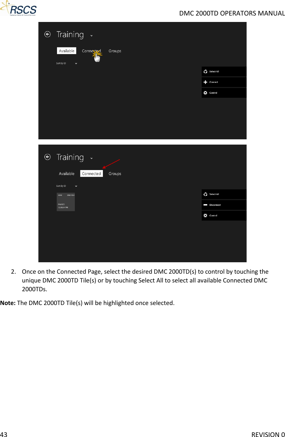
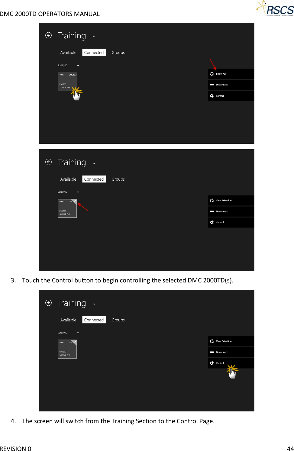
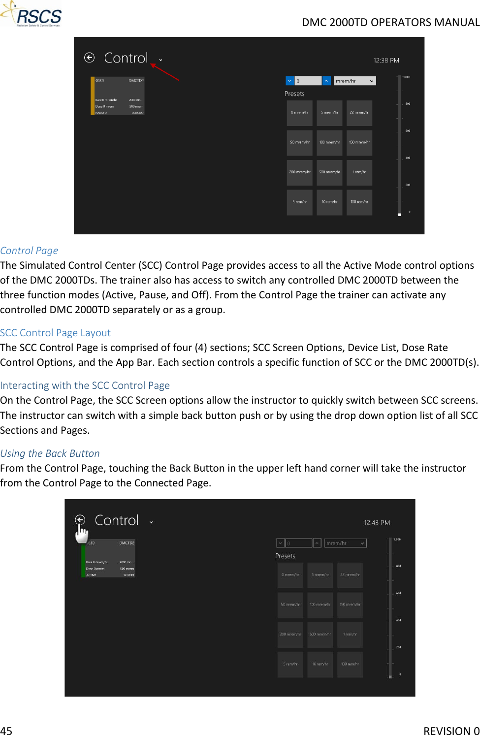
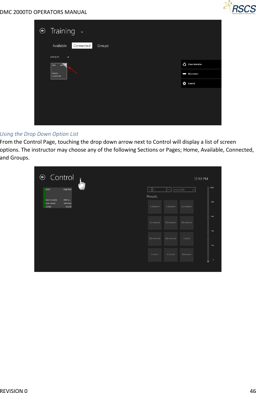
Exhibit D Users Manual per 2 1033 b3