Racom RIPEX-215 UHF RADIO MODEM User Manual RipEX Radio modem Router
Racom UHF RADIO MODEM RipEX Radio modem Router
UserManual.wiki
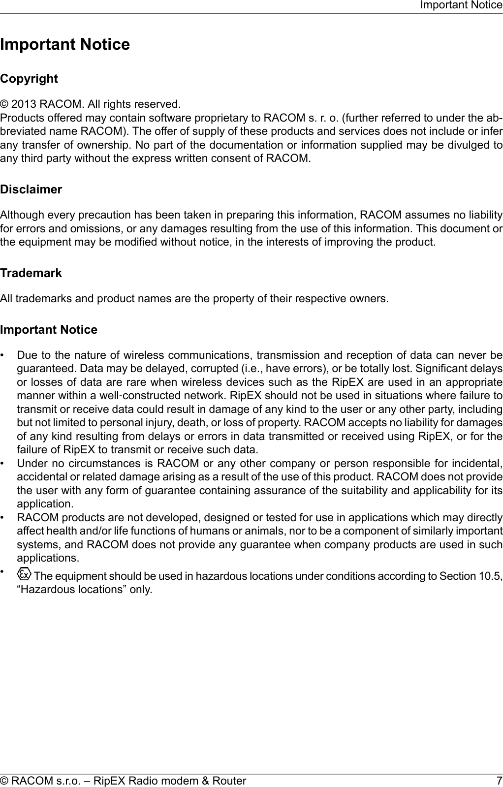
>
Racom
>
RIPEX 215 User Manual
User Manual
Navigation menu
Upload a User Manual
Namespaces
Wiki Guide
HTML
PDF
Info
Views
User Manual
Discussion / Help
Navigation
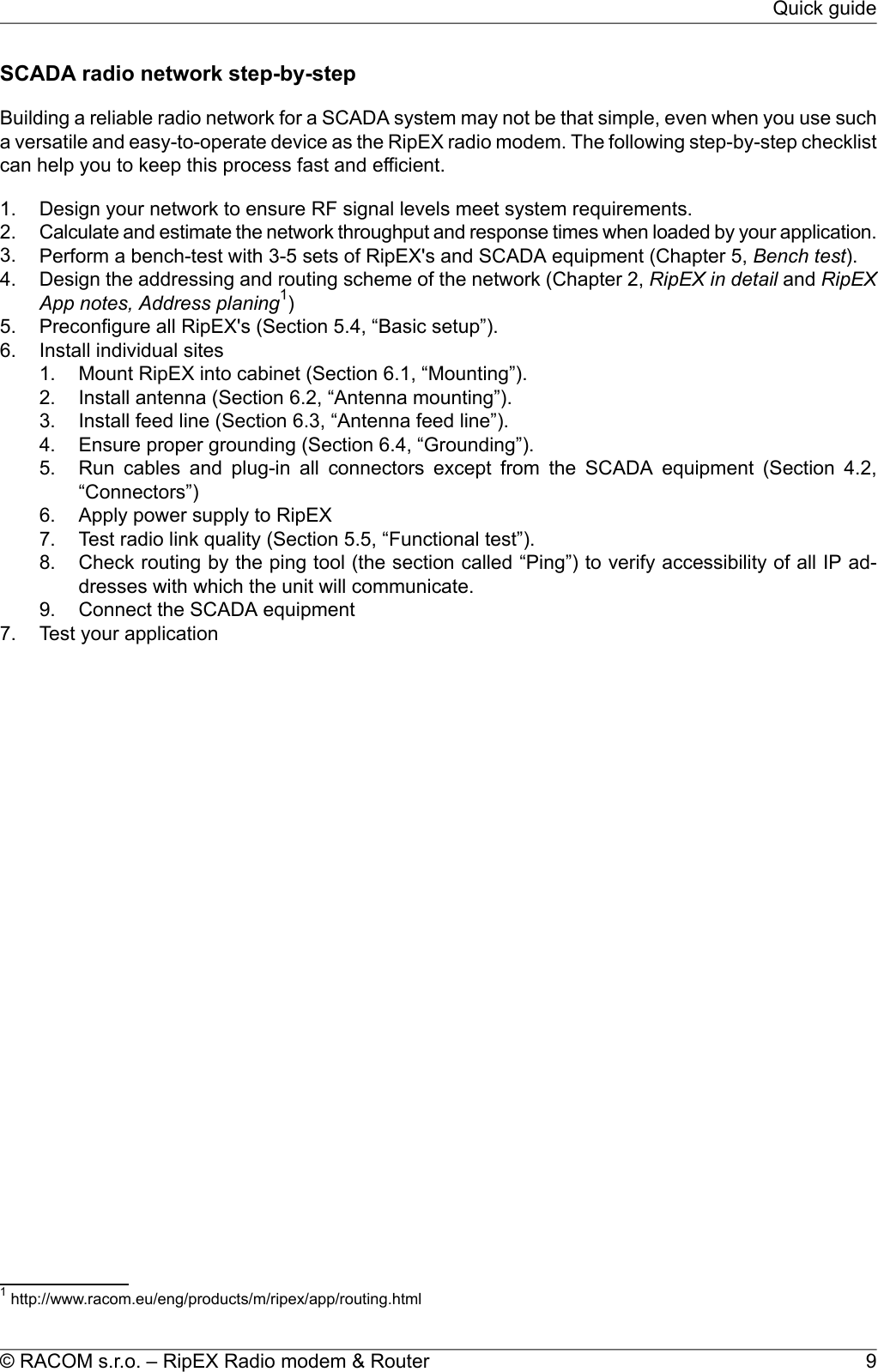
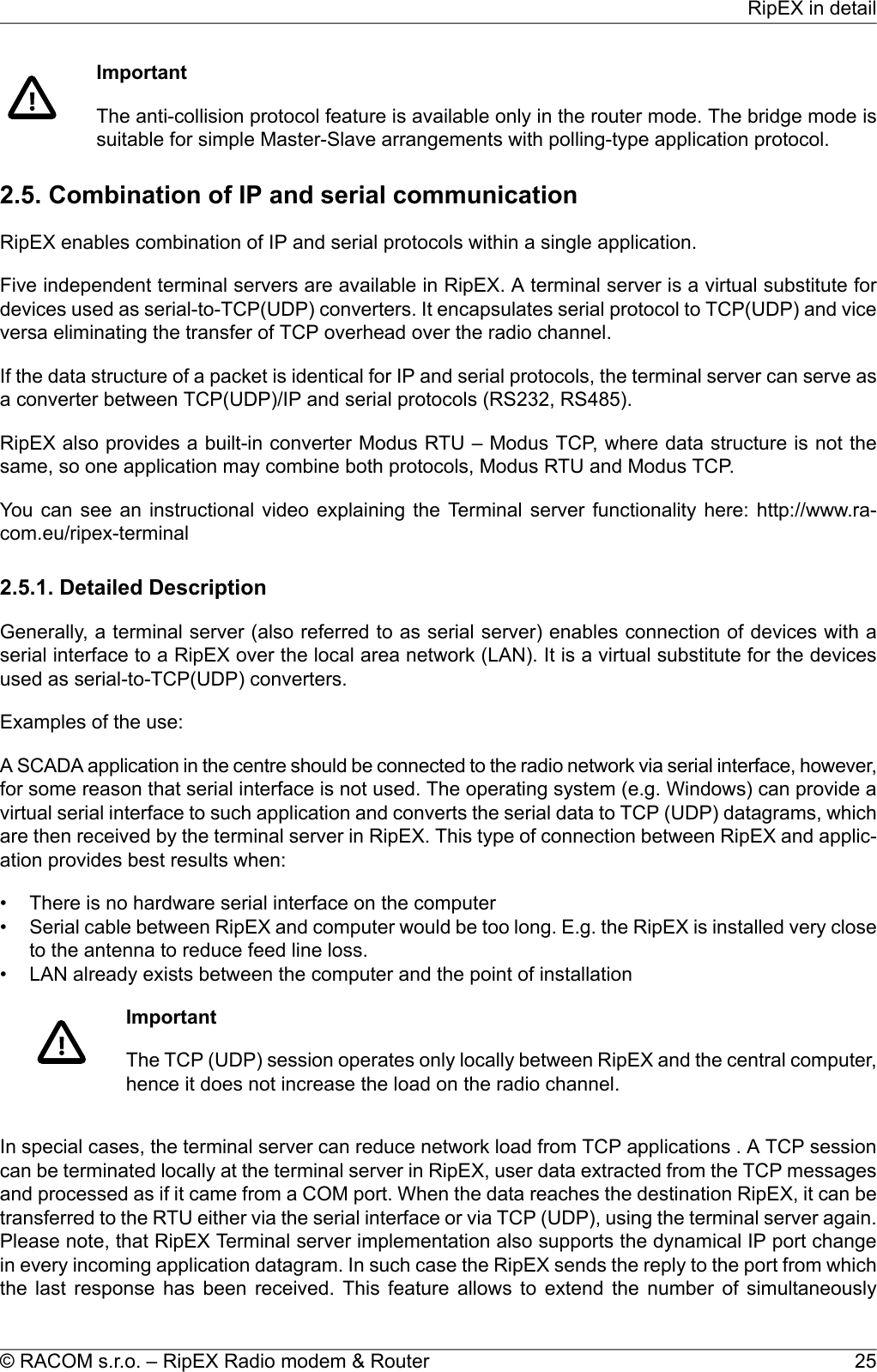
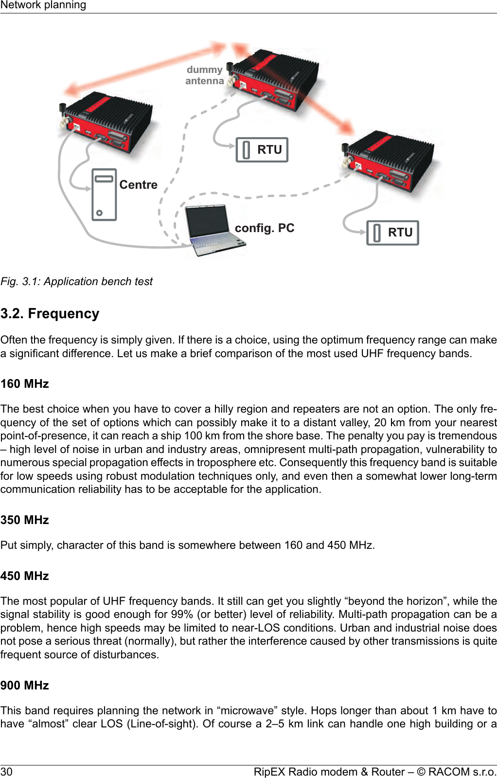
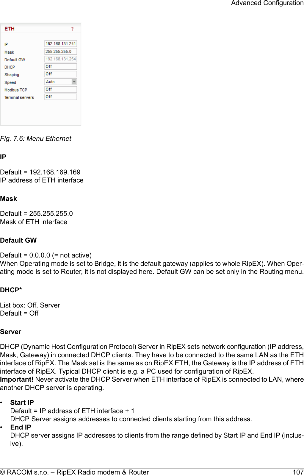
![opened TCP connections between the RipEX and the locally connected application up to 10 on eachTerminal server.2.6. Diagnostics & network managementRipEX radiomodem offers a wide range of built-in diagnostics and network management tools.2.6.1. LogsThere are ‘Neighbours’ and Statistic logs in RipEX. For both logs there is a history of 20 log filesavailable, so the total history of saved values is 20 days (assuming the default value of 1440 min. isused as the Log save period).NeighboursThe ‘Neighbours’ log provides information about neighbouring units (RipEX’s which can be accesseddirectly over the radio channel, i.e. without a repeater). Every RipEX on the network regularly broadcastsits status, the set of so called “Watched values”: the probability of packet loss when transmitting dataover the radio channel, current supply voltage, internal temperature, measured RF output power, theVoltage Standing Wave Ratio on the antenna feed line and the total number of packets received from/ transmitted to ETH, COM1, COM2 interfaces. In addition, the RipEX that records this data in its logalso keeps track of how many times it listened to its neighbouring unit as well as of the RSS and DQrecorded. See Adv. Conf., Diagnostic for more.StatisticThe ‘Statistic’ log provides information about the volume of data traffic on all interfaces: radio, ETH,COM1, COM2. It offers detailed information about the number of transmitted packets, their size andthe throughput per second. Moreover, a detailed division into user and service packets is available forthe radio channel. See chapter Adv. Conf., Diagnostic for more.2.6.2. GraphsAn independent database periodically stores the Watched values (see 'Neighbours' log above) fromup to five neighbouring RipEX's and from the local one, there including most important values from theStatistic log. All these values can be displayed as graphs.The graphs are available in summary and detailed versions. Detailed logging is triggered on when athreshold value has been reached for the specific item to enable a more detailed investigation into theunits’ operation when an alarm event occurs. Each graph can display two different elements at once,including their set thresholds. Each of the values may originate from a different RipEX unit.See chapter Adv. Conf., Graphs for more.2.6.3. SNMPRipEX implements an SNMPv1 and SNMPv2c. The values provided by RipEX are shown in the MIBtable, its Severity level is 3. RipEX also allows generating SNMP traps when thresholds have beenreached for the monitored values: RSScom, DQcom, TXLost[%], Ucc, Temp, PWR, VSWR, ETH[Rx/Tx],COM1[Rx/Tx], COM2[Rx/Tx], HW Alarm Input and/or for some internal warnings and errors.RipEX Radio modem & Router – © RACOM s.r.o.26RipEX in detail](https://usermanual.wiki/Racom/RIPEX-215/User-Guide-2641538-Page-26.png)
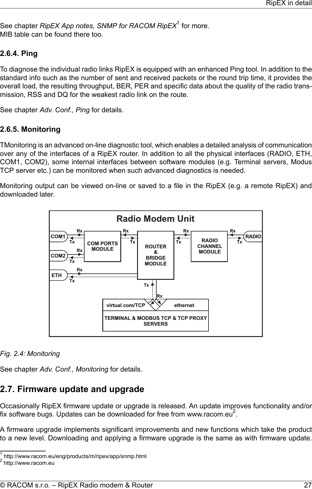
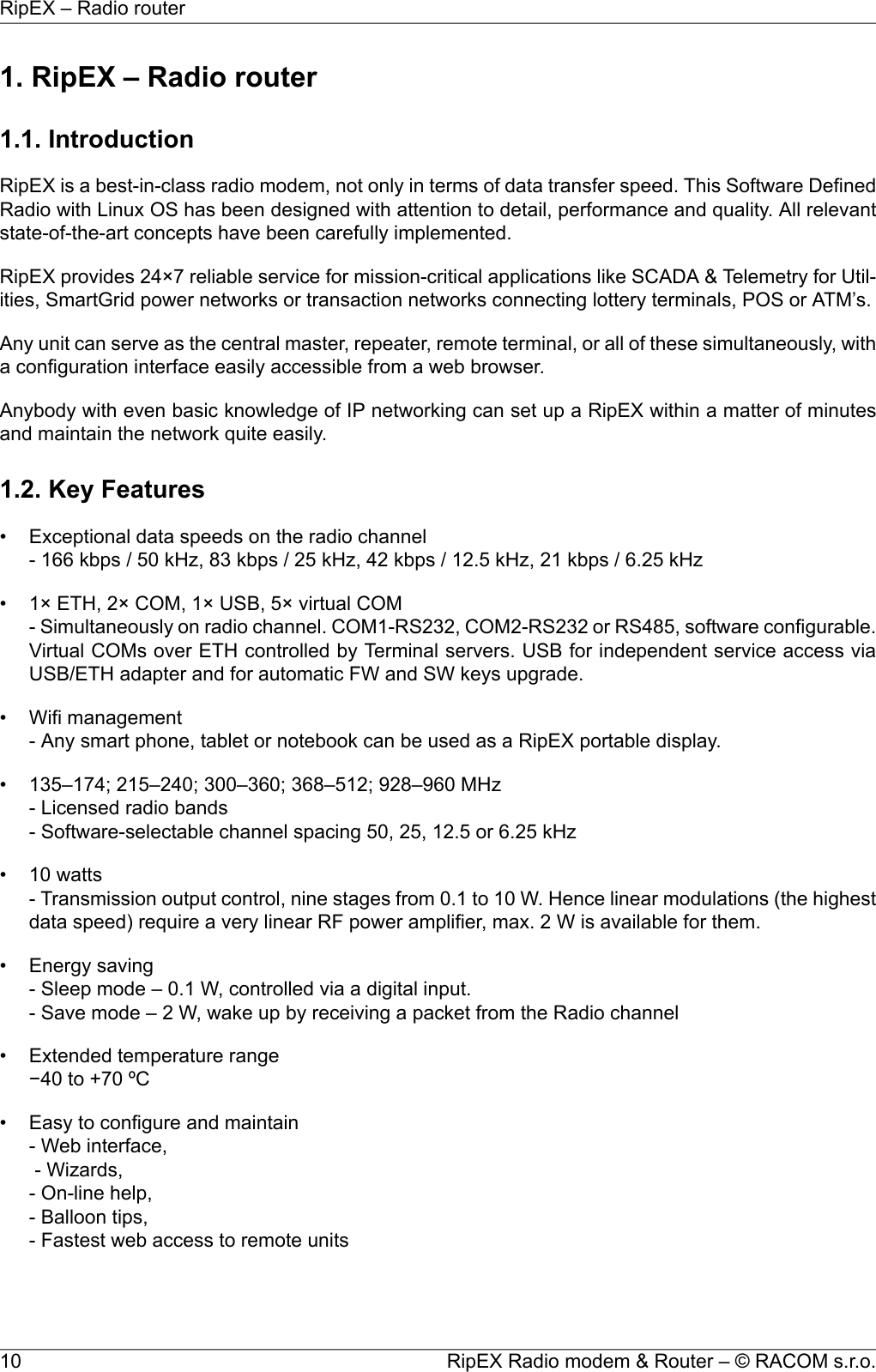
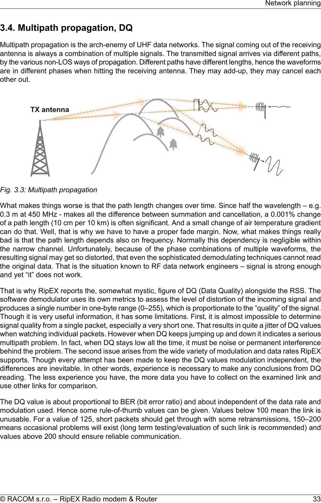
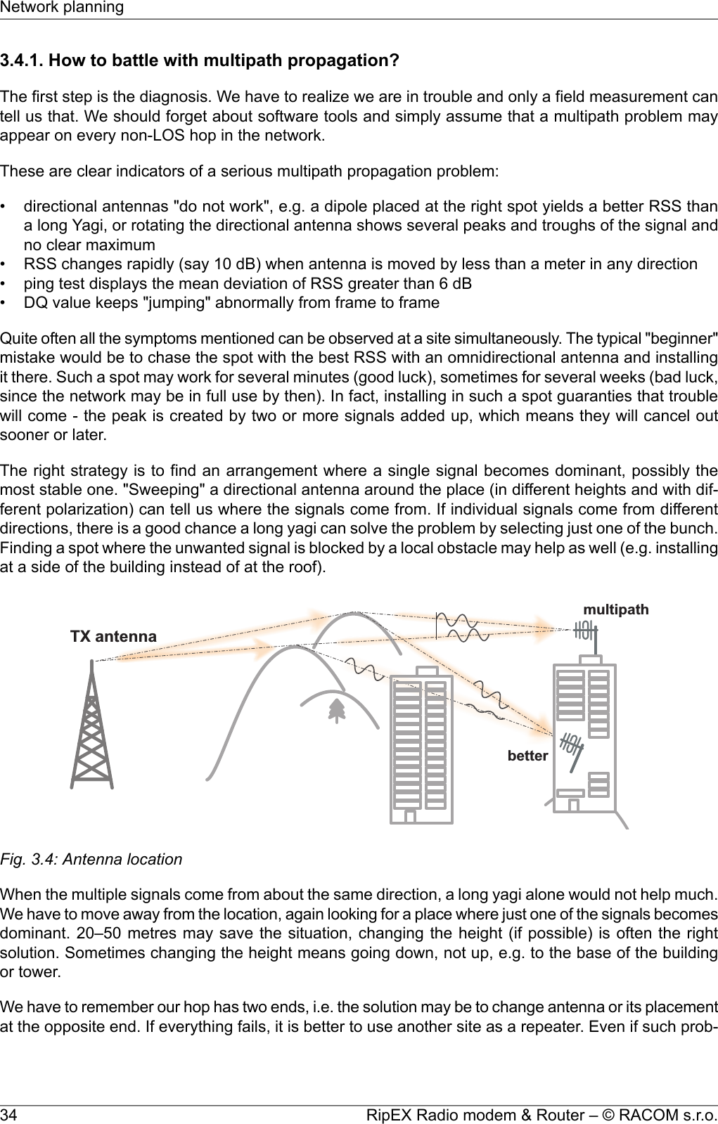
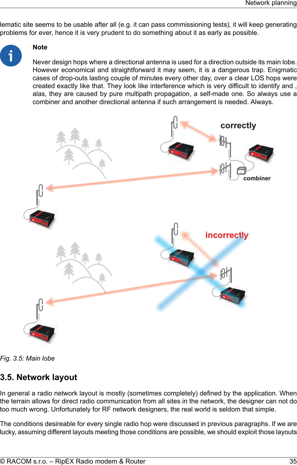
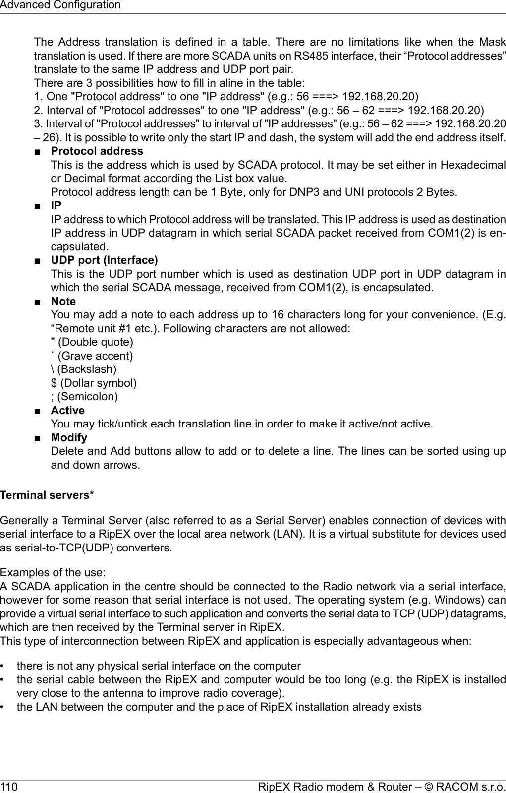
![bunch of trees in the middle, (which would be a fatal problem for e.g. an 11 GHz microwave). 900 MHzalso penetrates buildings quite well, in an industrial environment full of steel and concrete it may bethe best choice. The signal gets “everywhere” thanks to many reflections, unfortunately there is badnews attached to this - the reliability of high speed links in such environment is once again limited.Otherwise, if network capacity is your main problem, then 900 MHz allows you to build the fastest andmost reliable links. The price you pay (compared to lower frequency bands) is really the price – morerepeaters and higher towers increase the initial cost. Long term reliable performance is the reward.The three frequency bands discussed illustrate the simple basic rules – the higher the frequency, thecloser to LOS the signal has to travel. That limits the distance over the Earth's surface – there is noother fundamental reason why shorter wavelengths could not be used for long distance communication.On the other hand, the higher the frequency, the more reliable the radio link is. The conclusion is thenvery simple – use the highest frequency band you can.3.3. Signal budgetFor every radio hop which may be used in the network, the signal level at the respective receiver inputhas to be calculated and assessed against requirements. The fundamental requirements are two – thedata rate, which is dictated by total throughput and response times required by the application, and theavailability, which is again derived from the required reliability of the application. The data rate translatesto receiver sensitivity and the availability (e.g. 99,9 % percent of time) results in size of the fade margin.The basic rule of signal budget says, that the difference between the signal level at the receiver inputand the guaranteed receiver sensitivity for the given data rate has to be greater than the fade marginrequired:RX signal [dBm] – RX sensitivity [dBm] >= Fade margin [dB]To calculate the RX signal level, we follow the RF signal path:TXoutputRXinputfeedlinelossfeedlinelosspathlossTXantennagainRXantennagain+ +Fig. 3.2: Signal pathexample:RX signal [dBm] =dBm (TX output 1 W)+30.0+ TX output [dBm]dB (20m cable RG-213 U, 400 MHz)-2.5- TX antenna feeder loss [dB]dBi (half-wave dipole, 0 dBd)+2.1+TX antenna gain [dBi]dB calculated from field measurement)-125.0- Path loss [dB]dB (7-al Yagi antenna, 7.6 dBd)+9.7+ RX antenna gain [dBi]31© RACOM s.r.o. – RipEX Radio modem & RouterNetwork planning](https://usermanual.wiki/Racom/RIPEX-215/User-Guide-2641538-Page-31.png)
![dB (10 m cable RG-58 CU, 400 MHz)-3.1- RX antenna feeder loss [dB]dBm Received Signal Strength (RSS)= -88.8The available TX output power and guaranteed RX sensitivity level for the given data rate have to bedeclared by the radio manufacturer. RipEX values can be found in Table 4.6, “Technical parameters”and Chap Section 4.4.1, “Detailed Radio parameters”. Antenna gains and directivity diagrams have tobe supplied by the antenna manufacturer. Note that antenna gains against isotropic radiator (dBi)are used in the calculation. The figures of feeder cable loss per meter should be also known. Note thatcoaxial cable parameters may change considerably with time, especially when exposed to an outdoorenvironment. It is recommended to add a 50-100 % margin for ageing to the calculated feeder loss.3.3.1. Path loss and fade marginThe path loss is the key element in the signal budget. Not only does it form the bulk of the total loss,the time variations of path loss are the reason why a fade margin has to be added. In reality, very oftenthe fade margin is the single technical figure which expresses the trade-off between cost and perform-ance of the network. The decision to incorporate a particular long radio hop in a network, despite thatits fade margin indicates 90 % availability at best, is sometimes dictated by the lack of investment in ahigher tower or another repeater. Note that RipEXs Auto-speed feature allows the use of a lower datarate over specific hops in the network, without the need to reduce the rate and consequently thethroughput in the whole network. Lower data rate means lower (= better) value of receiver sensitivity,hence the fade margin of the respective hop improves. See the respective Application note to learnmore on the Auto-speed feature.When the signal path profile allows for LOS between the TX and RX antennas, the standard formulafor free-space signal loss (below) gives reliable results:Path loss [dB] = 20 * log10 (distance [km]) + 20 * log10 (frequency [MHz]) + 32.5In the real world the path loss is always greater. UHF radio waves can penetrate obstacles (buildings,vegetation), can be reflected from flat objects, can bend over round objects, can disperse behind sharpedges – there are numerous ways how a radio signal can propagate in non-LOS conditions. The addi-tional loss when these propagation modes are involved (mostly combined) is very difficult to calculate.There are sophisticated methods used in RF design software tools which can calculate the path lossand its variations (statistical properties) over a computer model of terrain. Their accuracy is unfortunatelyvery limited. The more obstacles on the path, the less reliable is the result. Such a tool can be veryuseful in the initial phase of network planning, e.g. to do the first network layout for the estimate of totalthroughput, however field measurements of every non-LOS radio hop should be done before the finalnetwork layout is designed.Determining the fade margin value is even more difficult. Nevertheless the software tools mentionedcan give some guidance, since they can calculate the statistical properties of the signal. Generally thefade margin (for given availability) is proportional to the difference between the real path loss and theLOS path loss over the same distance. Then it is about inversely proportional to frequency (in the UHFrange at least). To give an example for 10 km, non-LOS, hop on 450 MHz, fade margin of 20 dB is abare minimum. A field test may help again, provided it is run for longer period of time (hours-days).RipEX diagnostic tools (ping) report the mean deviation of the RSS, which is a good indication of thesignal stability. A multiple of the mean deviation should be added to the fade margin.RipEX Radio modem & Router – © RACOM s.r.o.32Network planning](https://usermanual.wiki/Racom/RIPEX-215/User-Guide-2641538-Page-32.png)
![• Do not underestimate ageing of coaxial cables, especially at higher frequencies. Designing a 900MHz site with 30 m long antenna cable run outdoors would certainly result in trouble two years later.• We recommend to use vertical polarization for all radio modem networks.3.8. Recommended valuesTo check individual radio link quality run Ping test with these settings: Ping type - RSS, Length [bytes]equal to the longest packets in the networks. Use Operating mode Bridge, when Router, ACK set toOff. Switch off all other traffic on the Radio channel used for testing. The test should run at least hours,preferrably day(s). The values below should guarantee a reliable radio link:•Fade marginMin. 20 dBFade margin [dB] = RSS (Received Signal Strenght) [dBm] – RX sensitivity [dBm].Respective RX sensitivity for different data rates can be found in Section 4.4.1, “Detailed Radioparameters”.•DQ (Data Quality)Min. 180•PER (Packet Error Rate)Max. 5 %39© RACOM s.r.o. – RipEX Radio modem & RouterNetwork planning](https://usermanual.wiki/Racom/RIPEX-215/User-Guide-2641538-Page-39.png)
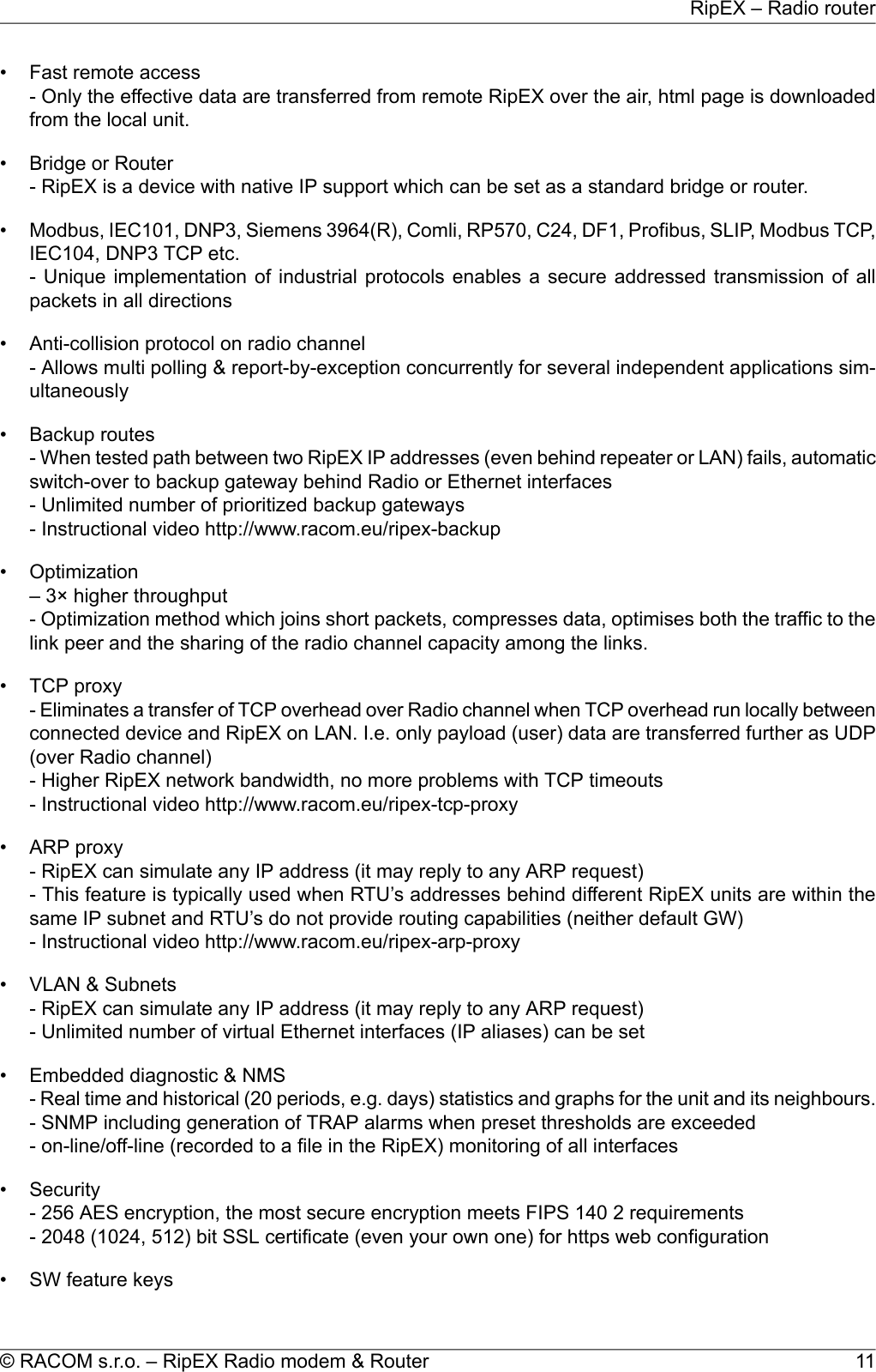
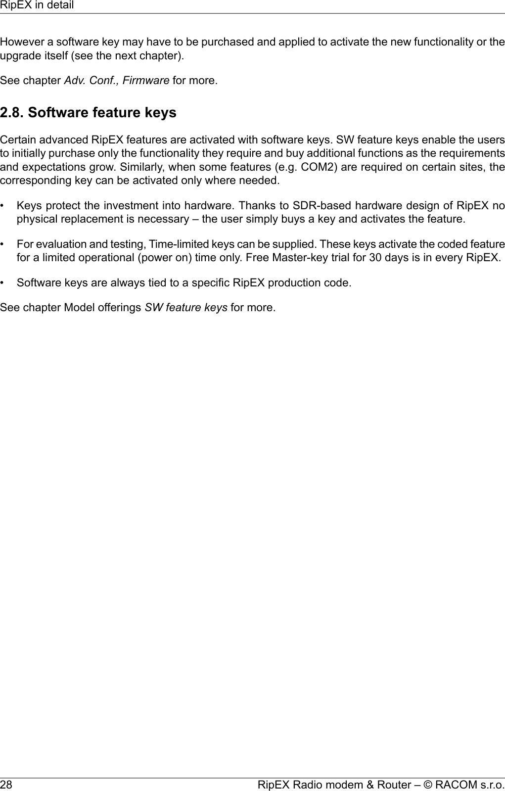
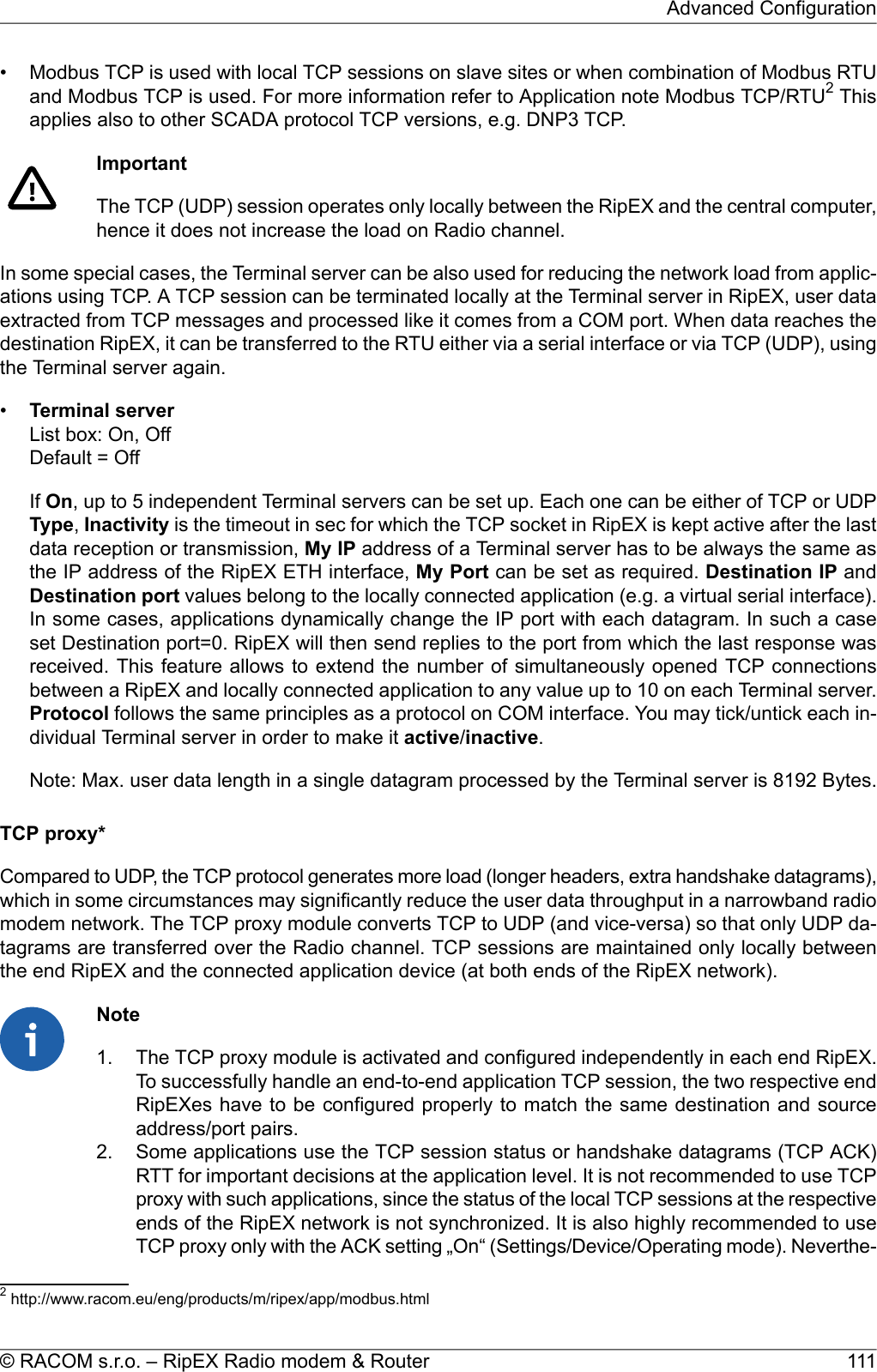
![4.4. Technical specificationTab. 4.6: Technical parametersRadio parameters135–154; 154–174; 215–240; 300–320; 320–340; 340–360;368–400; 400–432; 432–470; 470–512; 928–960 MHz – DetailFrequency bands6.25 / 12.5 / 25 / 50 kHz[1]Channel spacing±1.0 ppmFrequency stabilityDetailLinear: 16DEQAM, D8PSK, π/4DQPSK, DPSKExponential (FM): 4CPFSK, 2CPFSKModulationmax. 2 Wmax. 10 WLin.: 139 – 104 – 69 – 35 kbpsExp.: 42 – 21 kbps50 kHzRF Data rate – CEDetailmax. 2 Wmax. 10 W83 – 63 – 42 – 21 kbps21 – 10 kbps25 kHzmax. 2 Wmax. 10 W42 – 31 – 21 kbps10 – 5 kbps12.5 kHzmax. 2 Wmax. 10 W21 – 16 – 10 – 5 kbps5 – 3 kbps6.25 kHzmax. 2 Wmax. 10 WLin.: 139 – 104 – 69 – 35 kbpsExp.: 42 – 21 kbps50 kHzRF Data rate – FCCDetailmax. 2 Wmax. 10 W69 – 52 – 35 kbps[2]21 kbps25 kHzmax. 2 Wmax. 10 W35 – 26 – 17 kbps10 kbps12.5 kHzmax. 2 Wmax. 10 W17 – 13 – 9 kbps5 kbps6.25 kHzmax. 2 Wmax. 10 WLin.: 166 – 125 – 83 – 42 kbpsExp.: 42 – 21 kbps50 kHzRF Data rate – Unlim-itedDetailOn/Off, ¾ Trellis code with Viterbi soft-decoderFEC (Forward Error Correction)TransmitterLinear: 0.5 - 1.0 - 2.0 WExponential(FM): 0.1 - 0.2 - 0.5 - 1.0 - 2.0 - 3.0 - 4.0 - 5.0 -10 W[3]RF Output power(Both Carrier and Modulated)ContinuousDuty cycle< 1.5 msRx to Tx Time> 40 dBIntermodulation Attenuation< −36 dBmSpurious Emissions (Conducted)< −36 dBmRadiated Spurious Emissions< −60 dBcAdjacent channel power< −60 dBcTransient adjacent channel powerReceiver51© RACOM s.r.o. – RipEX Radio modem & RouterProduct](https://usermanual.wiki/Racom/RIPEX-215/User-Guide-2641538-Page-51.png)
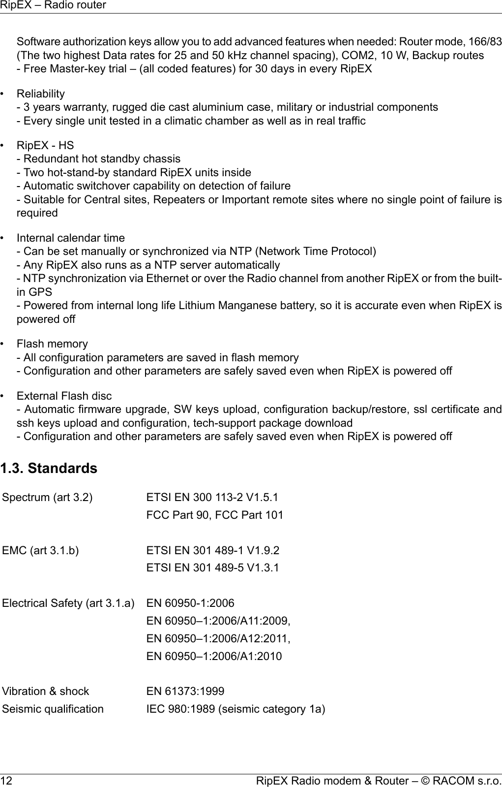
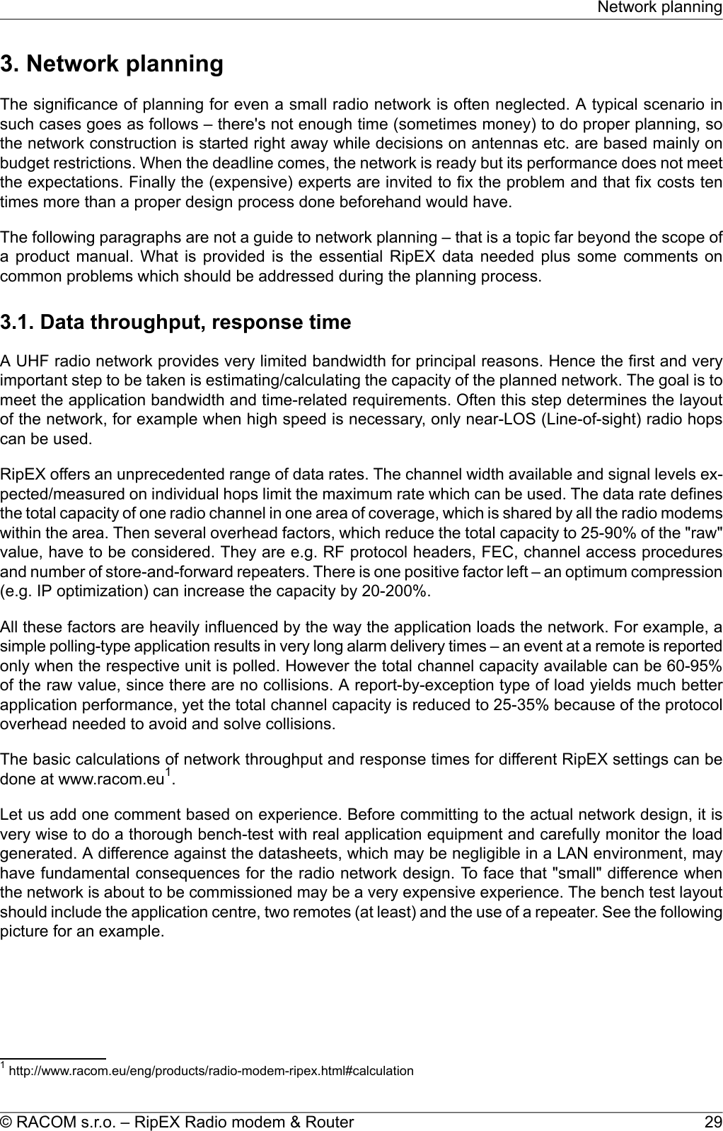
![DetailSensitivity50 kHz @ −3 dB BWAnti-aliasing Selectivity< 1.5 msTx to Rx Time20 dBm (100 mW)Maximum Receiver Input Power< −57 dBmRx Spurious Emissions (Conducted)< −57 dBmRadiated Spurious EmissionsDetailBlocking or desensitization> 70 dBSpurious response rejection[1] 50 kHz channel spacing is HW dependend. Units with older version boardsare still in production.50 kHz channel spacing requirement kindly specify in your order.6.25 kHz channel spacing is not available for RipEX-928.[2] RipEX-928: 56 – 42 – 28 kbps.[3] For output power 10 W it is recommended to use input power above 11 VDC.RipEX-470, RipEX-928 – max. RF Output power 8 W.Electrical10 to 30 VDC, negative GNDPrimary power5 W/13.8 V; 4.8 W/24 V; (Radio part < 2 W)RxPower consumptionRF powerTx4CPFSK, 2CPFSK13.8 V 24V13.8 W 13.2 W0.1 W15.2 W 14.4 W1 W33.1 W 31.2 W5 W41.4 W 38.4 W10 W30.4 W 30 W0.5 WTx16DEQAM, D8PSK,π/4DQPSK30.4 W 30 W1 W30.4 W 30 W2 W0.1 WSleep mode2 WSave modeInterfacesRJ4510/100 Base-T Auto MDI/MDIXEthernetDB9FRS232COM 1 300–115 200 bpsDB9FRS232/RS485 SW configurableCOM 2 300–115 200 bpsHost AUSB 1.1USBTNC female50 ΩAntennaLED panelPower, ETH, COM1, COM2, Rx, Tx, Status7× tri-color status LEDsRipEX Radio modem & Router – © RACOM s.r.o.52Product](https://usermanual.wiki/Racom/RIPEX-215/User-Guide-2641538-Page-52.png)
![EnviromentalIP40IP Code (Ingress Protection)> 500.000 hours (> 50 years)MTBF (Mean Time Between Failure)−40 to +70 °C (−40 to +158 °F)Operating temperature5 to 95 % non-condensingOperating humidity−40 to +85 °C (−40 to +185 °F) / 5 to 95 % non-condensingStorageMechanicalRugged die-cast aluminiumCasing50 H × 150 W × 118 mm D (1.97× 5.9 × 4.65 in)Dimensions1.1 kg (2.4 lbs)WeightDIN rail, L-bracket, Flat-bracket, 19" Rack shelfMountingSWBridge / RouterOperating modesModbus, IEC101, DNP3, UNI, Comli, DF1, RP570, Profibus, …User protocols on COMModbus TCP, IEC104, DNP3 TCP, Comli TCP, Terminal server…User protocols on EthernetModbus RTU / Modbus TCP, DNP3 / DNP3 TCPSerial to IP convertorsProtocol on Radio channelYesMulti master applicationsYesReport by exceptionYesCollision Avoidance CapabilityYesRemote to Remote communicationYesAddressed & acknowledged serialSCADA protocolsCRC 32Data integrity controlAES256Encryptionup to 3× higher throughputOptimizationDiagnostic and ManagementYes (ping with RSS, Data Quality, Homogenity)Radio link testingDevice – Ucc, Temp, PWR, VSWR, *HW Alarm Input.Radio channel – *RSScom, *DQcom, TXLost[%]User interfaces – ETH[Rx/Tx], COM1[Rx/Tx], COM2[Rx/Tx]* not broadcastWatched values (Can be broadcastto neighbouring units. Received infodisplayed in Neighbours table)For Rx/Tx Packets on User interfaces (ETH, COM1, COM2) andfor User data and Radio protocol (Repeates, Lost, ACK etc.) onRadio channelStatisticsFor Watched values and StatisticsGraphs20 periods (configurable, e.g. days)History (Statistics, Neighbours,Graphs)SNMPv1, SNMPv2cTrap alarms generation as per settingsSNMPReal time/Save to file analysis of all physical interfaces (RADIO,ETH, COM1, COM2) and some internal interfaces betweenMonitoring53© RACOM s.r.o. – RipEX Radio modem & RouterProduct](https://usermanual.wiki/Racom/RIPEX-215/User-Guide-2641538-Page-53.png)
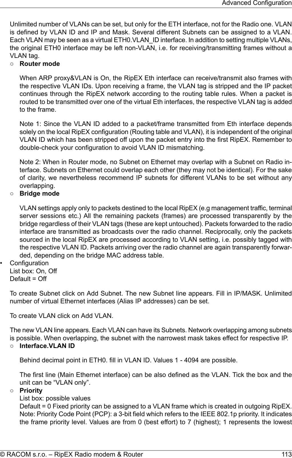
![4.4.1. Detailed Radio parametersThe very first parameter which is often required for consideration is the receiver sensitivity. Anyoneinterested in the wireless data transmission probably aware what this parameter means, but we shouldregard it simultaneously in its relation to other receiver parameters, especially blocking and desensitiz-ation. Today’s wireless communication arena tends to be overcrowded and a modern radio modem,which is demanded to compete with others in that environment, should have good dynamic range thatis defined by the parameters listed above. Receiver of a radio modem, which is designed purely foroptimum sensitivity, will not be able to give proper performance. However, the main receiver parametersdetermining its dynamic range go against each other and a clear trade-off between the sensitivity andthe blocking is therefore an essential assumption. Then, from the viewpoint of a logical comparison,the consequence of better receiver sensitivity can be easily seen – a lower power level of the blockingand degradation parameters generally.Blocking or desensitization values were determined according to the standards EN 302 561 V1.2.1 for50 kHz channel, EN 300 113-1 V1.7.1 for 25 and 12.5 kHz channels, and ETSI 301 166-1 V1.3.2 forchannel 6.25 kHz.Tab. 4.8: Unlimited 50 kHzUnlimited 50 kHz RxBlocking ordesensitization [dBm]Sensitivity [dBm]Classification±10 MHz±5 MHz±1 MHzBER 10-6BER 10-3BER 10-2ModulationFECkbps-14-14-16-107-111-1142CPFSK0.7515.62-14-15-16-106-110-1132CPFSK1.0020.83-18-18-19-101-105-1084CPFSK0.7531.25-18-19-19-100-104-1074CPFSK1.0041.67-9-10-12-105-109-112DPSK0.7531.25-9-11-12-104-108-111DPSK1.0041.67-3-4-4-100-104-107π/4-DQPSK0.7562.49-4-5-5-99-103-106π/4-DQPSK1.0083.33-8-8-8-94-98-101D8PSK0.7593.75-8-8-8-93-97-100D8PSK1.00125.00-5-6-6-91-95-9816DEQAM0.75125.00-5-6-6-90-94-9716DEQAM1.00166.67Unlimited 50 kHz Tx26 dB BandwidthOBW 99% [kHz]ClassificationEmissionModulationkbps30.622.124K0F1DBN2CPFSK20.8331.723.924K0F1DDN4CPFSK41.6751.045.145K0G1DBNDPSK41.6751.044.845K0G1DDNπ/4-DQPSK83.3351.345.345K0G1DEND8PSK12551.044.745K0D1DEN16DEQAM166.6755© RACOM s.r.o. – RipEX Radio modem & RouterProduct](https://usermanual.wiki/Racom/RIPEX-215/User-Guide-2641538-Page-55.png)
![Tab. 4.9: CE 50 kHzCE 50 kHz RxBlocking ordesensitization [dBm]Sensitivity [dBm]Classification±10 MHz±5 MHz±1 MHzBER 10-6BER 10-3BER 10-2ModulationFECkbps-14-14-16-107-111-1142CPFSK0.7515.62-14-15-16-106-110-1132CPFSK1.0020.83-18-18-19-101-105-1084CPFSK0.7531.25-18-19-19-100-104-1074CPFSK1.0041.67-15-15-15-105-109-112DPSK0.7526.04-15-15-15-104-108-110DPSK1.0034.72-17-21-21-100-104-107π/4-DQPSK0.7552.08-17-21-21-99-103-106π/4-DQPSK1.0069.44-15-21-20-96-99-102D8PSK0.7578.12-16-21-20-95-98-101D8PSK1.00104.17-14-17-17-95-98-10116DEQAM0.75104.17-15-1717-94-97-10016DEQAM1.00138.89CE 50 kHz Tx26 dB BandwidthOBW 99% [kHz]ClassificationEmissionModulationkbps30.622.124K0F1DBN2CPFSK20.8331.723.924K0F1DDN4CPFSK41.6745.539.340K0G1DBNDPSK34.7245.639.240K0G1DDNπ/4-DQPSK69.4444.839.540K0G1DEND8PSK104.1745.139.140K0D1DEN16DEQAM138.89RipEX Radio modem & Router – © RACOM s.r.o.56Product](https://usermanual.wiki/Racom/RIPEX-215/User-Guide-2641538-Page-56.png)
![Tab. 4.10: CE 25 kHzCE 25 kHz RxBlocking ordesensitization [dBm]Sensitivity [dBm]Classification±10 MHz±5 MHz±1 MHzBER 10-6BER 10-3BER 10-2ModulationFECkbps-5-6-8-111-115-1182CPFSK0.757.81-7-8-10-110-114-1172CPFSK1.0010.42-7-9-9-107-112-1154CPFSK0.7515.63-9-11-11-104-110-1134CPFSK1.0020.83-5-6-6-107-112-114DPSK0.7515.62-7-8-8-106-111-113DPSK1.0020.83-3-4-4-106-110-113π/4-DQPSK0.7531.25-5-6-6-104-108-111π/4-DQPSK1.0041.66-8-8-8-98-103-106D8PSK0.7546.87-9.5-10-10-95-101-104D8PSK1.0062.49-5-6-6-95-101-10416DEQAM0.7562.49-7-8-8-93-99-10216DEQAM1.0083.32CE 25 kHz Tx26 dB BandwidthOBW 99% [kHz]ClassificationEmissionModulationkbps19.613.813K8F1DBN2CPFSK10.4218.114.214K2F1DDN4CPFSK20.8327.123.524K0G1DBNDPSK20.8327.223.924K0G1DDNπ/4-DQPSK41.6726.923.524K0G1DEND8PSK62.4927.323.924K0D1DEN16DEQAM83.3257© RACOM s.r.o. – RipEX Radio modem & RouterProduct](https://usermanual.wiki/Racom/RIPEX-215/User-Guide-2641538-Page-57.png)
![Tab. 4.11: CE 12.5 kHzCE 12.5 kHz RxBlocking ordesensitization [dBm]Sensitivity [dBm]Classification±10 MHz±5 MHz±1 MHzBER 10-6BER 10-3BER 10-2ModulationFECkbps-3-4-6-113-117-1202CPFSK0.753.91-5-6-8-112-116-1192CPFSK1.005.21-5-6-6-108-114-1174CPFSK0.757.81-7-8-8-105-112-1154CPFSK1.0010.42-3-4-4-110-114-116DPSK0.757.81-5-6-6-109-113-115DPSK1.0010.42-2-3-3.5-109-113-115π/4-DQPSK0.7515.62-3-4-4-106-111-114π/4-DQPSK1.0020.83-5-6-6-101-106-109D8PSK0.7523.44-7-8-8-98-104-107D8PSK1.0031.25-2-3-3-99-104-10716DEQAM0.7531.25-4-5-5-96-102-10516DEQAM1.0041.67CE 12.5 kHz Tx26 dB BandwidthOBW 99% [kHz]ClassificationEmissionModulationkbps9.66.97K00F1DBN2CPFSK5.218.56.87K00F1DDN4CPFSK10.4213.611.911K9G1DBNDPSK10.4213.611.811K9G1DDNπ/4-DQPSK20.8413.411.811K9G1DEND8PSK31.2513.511.811K9D1DEN16DEQAM41.66RipEX Radio modem & Router – © RACOM s.r.o.58Product](https://usermanual.wiki/Racom/RIPEX-215/User-Guide-2641538-Page-58.png)
![Tab. 4.12: CE 6.25 kHzCE 6.25 kHz RxBlocking ordesensitization [dBm]Sensitivity [dBm]Classification±10 MHz±5 MHz±1 MHzBER 10-6BER 10-3BER 10-2ModulationFECkbps+5.5+1.0-0.5-114-120-1222CPFSK0.751.96+4.0-1.0-2.5-113-119-1212CPFSK1.002.61+5.0-0.0-1.5-111-116-1194CPFSK0.753.91+3.0-1.5-3.5-108-114-1174CPFSK1.005.217.01.50.0-113-118-121DPSK0.753.915.0-0.5-2.0-112-117-119DPSK1.005.216.03.0+1.0-112-115-117π/4-DQPSK0.757.824.01.0-0.5-110-113-116π/4-DQPSK1.0010.424.01.0-1.0-104-109-111D8PSK0.7511.722.0-1.0-3.0-104-109-111D8PSK1.0015.631.5-2.0-7.5-103-107-11016DEQAM0.7515.630.0-3.5-5.5-99-104-10716DEQAM1.0020.83CE 6.25 kHz Tx26 dB BandwidthOBW 99% [kHz]ClassificationEmissionModulationkbps4.352.953K00F1DBN2CPFSK2.613.923.173K00F1DDN4CPFSK5.216.715.916K00G1DBNDPSK5.216.818.946K00G1DDNπ/4-DQPSK10.426.685.936K00G1DEND8PSK15.626.745.816K00D1DEN16DEQAM20.8359© RACOM s.r.o. – RipEX Radio modem & RouterProduct](https://usermanual.wiki/Racom/RIPEX-215/User-Guide-2641538-Page-59.png)
![Tab. 4.13: FCC 50 kHzFCC 50 kHz RxBlocking ordesensitization [dBm]Sensitivity [dBm]Classification±10 MHz±5 MHz±1 MHzBER 10-6BER 10-3BER 10-2ModulationFECkbps-15-16-16-108-112-1152CPFSK0.7515.62-15-16-17-107-111-1132CPFSK1.0020.83-15-21-21-103-107-1104CPFSK0.7531.25-16-21-21-102-106-1094CPFSK1.0041.67-15-15-15-105-109-112DPSK0.7526.04-15-15-15-104-108-110DPSK1.0034.72-17-21-21-100-104-107π/4-DQPSK0.7552.08-17-21-21-99-103-106π/4-DQPSK1.0069.44-15-21-20-96-99-102D8PSK0.7578.12-16-21-20-95-98-101D8PSK1.00104.17-14-17-17-95-98-10116DEQAM0.75104.17-15-1717-94-97-10016DEQAM1.00138.89FCC 50 kHz Tx26 dB BandwidthOBW 99% [kHz]ClassificationEmissionModulationkbps37.028.028K0F1D4CPFSK41.6745.539.340K0G1DDPSK34.7245.639.240K0G1Dπ/4-DQPSK69.4444.839.540K0G1DD8PSK104.1745.139.140K0D1D16DEQAM138.89Tab. 4.14: FCC 25 kHzFCC 25 kHz RxBlocking ordesensitization [dBm]Sensitivity [dBm]Classification±10 MHz±5 MHz±1 MHzBER 10-6BER 10-3BER 10-2ModulationFECkbps-0-1-3-108-113-1164CPFSK0.7515.63-1-2-5-105-111-1144CPFSK1.0020.83-1-2-4-107-111-114π/4-DQPSK0.7526.04-2-4-6-105-109-112π/4-DQPSK1.0034.72-5-7-9-99-105-108D8PSK0.7539.06-7-9-11-96-103-106D8PSK1.0052.08-8-9-12-96-103-10616DEQAM0.7552.08-10-12-14-94-101-10416DEQAM1.0069.44RipEX Radio modem & Router – © RACOM s.r.o.60Product](https://usermanual.wiki/Racom/RIPEX-215/User-Guide-2641538-Page-60.png)
![FCC 25 kHz Tx26 dB BandwidthOBW 99% [kHz]ClassificationEmissionModulationkbps23.618.518K6F1D4CPFSK20.8322.819.719K8G1Dπ/4-DQPSK34.7222.619.819K8G1DD8PSK52.0822.619.919K8D1D16DEQAM69.44Tab. 4.15: FCC 25 kHz RipEX-928, RipEX-215FCC 25 kHz Rx RipEX-928, RipEX-215Blocking ordesensitization [dBm]Sensitivity [dBm]Classification±10 MHz±5 MHz±1 MHzBER 10-6BER 10-3BER 10-2ModulationFECkbps-8-8-8-106-112-1154CPFSK0.7515.63-10-10-10-104-110-1134CPFSK1.0020.83-9-9-9-108-112-115π/4-DQPSK0.7520.84-11-11-11-105-110-113π/4-DQPSK1.0027.78-8-8-8-101-107-110D8PSK0.7531.25-9-9-9-98-105-108D8PSK1.0041.67-11-11-11-96-103-10616DEQAM0.7541.67-13-13-13-94-101-10416DEQAM1.0055.56FCC 25 kHz Tx RipEX-928, RipEX-21526 dB BandwidthOBW 99% [kHz]ClassificationEmissionModulationkbps22.615.916K0F1D4CPFSK20.8318.215.916K0G1Dπ/4-DQPSK27.7818.015.916K0G1DD8PSK41.6718.115.916K0D1D16DEQAM55.5661© RACOM s.r.o. – RipEX Radio modem & RouterProduct](https://usermanual.wiki/Racom/RIPEX-215/User-Guide-2641538-Page-61.png)
![Tab. 4.16: FCC 12.5 kHzFCC 12.5 kHz RxBlocking ordesensitization [dBm]Sensitivity [dBm]Classification±10 MHz±5 MHz±1 MHzBER 10-6BER 10-3BER 10-2ModulationFECkbps-4-5-5-108-114-1174CPFSK0.757.81-6-7-7-105-112-1154CPFSK1.0010.42-2-2-2-109-113-115π/4-DQPSK0.7513.02-3-4-4-106-111-114π/4-DQPSK1.0017.36-5-6-6-101-106-109D8PSK0.7519.53-7-8-8-98-104-107D8PSK1.0026.04-2-3-3-99-104-10716DEQAM0.7526.04-4-5-5-96-102-10516DEQAM1.0034.72FCC 12.5 kHz Tx26 dB BandwidthOBW 99% [kHz]ClassificationEmissionModulationkbps11.38.68K60F1D4CPFSK10.4211.39.8310K0G1Dπ/4-DQPSK17.3611.29.8710K0G1DD8PSK26.0411.39.8810K0G1D16DEQAM34.72Tab. 4.17: FCC 6.25 kHzFCC 6.25 kHz RxBlocking ordesensitization [dBm]Sensitivity [dBm]Classification±10 MHz±5 MHz±1 MHzBER 10-6BER 10-3BER 10-2ModulationFECkbps-2-2-2-112-117-1204CPFSK0.753.91-3-4-4-109-115-1184CPFSK1.005.21-2-3-3-113-116-118π/4-DQPSK0.756.51-4-5-5-111-114-117π/4-DQPSK1.008.68-2-2-2-105-110-112D8PSK0.759.77-3-4-4-102-107-110D8PSK1.0013.02-2-3-3-103-107-11016DEQAM0.7513.02-4-5-5-100-105-10816DEQAM1.0017.36RipEX Radio modem & Router – © RACOM s.r.o.62Product](https://usermanual.wiki/Racom/RIPEX-215/User-Guide-2641538-Page-62.png)
![FCC 6.25 kHz Tx26 dB BandwidthOBW 99% [kHz]ClassificationEmissionModulationkbps5.013.553K60F1D4CPFSK5.215.634.895K00G1Dπ/4-DQPSK8.685.564.885K00G1DD8PSK13.025.634.875K00G1D16DEQAM17.36Tab. 4.18: Narrow 25 kHzNarrow 25 kHz RxBlocking ordesensitization [dBm]Sensitivity [dBm]Classification±10 MHz±5 MHz±1 MHzBER 10-6BER 10-3BER 10-2ModulationFECkbps-5-6-8-111-115-1182CPFSK0.757.81-7-8-10-110-114-1172CPFSK1.0010.42-7-9-9-107-112-1154CPFSK0.7515.63-9-11-11-104-110-1134CPFSK1.0020.83-6-7-7-109-114-116DPSK0.7510.41-7-8-8-108-113-115DPSK1.0013.89-8-8-8-107-111-113π/4-DQPSK0.7520.84-8-8-9-106-110-112π/4-DQPSK1.0027.78-8-8-9-101-105-108D8PSK0.7531.25-9-10-10-100-104-107D8PSK1.0041.67-9-9-11-99-103-10616DEQAM0.7541.67-9-10-11-95-101-10416DEQAM1.0055.56Narrow 25 kHz Tx26 dB BandwidthOBW 99% [kHz]ClassificationEmissionModulationkbps19.613.813K8F1DBN2CPFSK10.4218.114.214K2F1DDN4CPFSK20.8318.215.915K9G1DBNDPSK13.8918.215.915K9G1DDNπ/4-DQPSK27.7818.015.915K9G1DEND8PSK41.6718.115.915K9D1DEN16DEQAM55.56NoteAll the Sensitivities above are guaranteed ones, i.e. every single unit has got typicallyeven better values for 0–4 dB.1.2. BER (Bit Error Rate) is calculated from PER (Packet Error Rate) when packet size was60 Bytes.63© RACOM s.r.o. – RipEX Radio modem & RouterProduct](https://usermanual.wiki/Racom/RIPEX-215/User-Guide-2641538-Page-63.png)
![Default = BridgeBridgeBridge mode is suitable for Point-to-Multipoint networks, where Master-Slave application with polling-type communication protocol is used. RipEX in Bridge mode is as easy to use as a simple transparentdevice, while allowing for a reasonable level of communication reliability and spectrum efficiency insmall to medium size networks.poIn Bridge mode, the protocol on Radio channel does not have the collision avoidance capability. Thereis CRC check of data integrity, i.e. once a message is delivered, it is 100% error free.All the messages received from user interfaces (ETH&COM's) are immediately transmitted to Radiochannel, without any checking or processing.ETH: The whole network of RipEX units behaves like a standard Ethernet network bridge, so the Eth-ernet interface IP address itself is not significant. Each ETH interface automatically learns which devices(MAC addresses) lie in the local LAN and which devices are accessible via the Radio channel. Con-sequently only the Ethernet frames addressed to remote devices are physically transmitted on theRadio channel. This arrangement saves the precious RF spectrum from extra load which would otherwisebe generated by local traffic in the LAN (the LAN to which the respective ETH interface is connected).COM1,COM2: all frames received from COM1(2) are broadcast over Radio channel and transmittedto all COM's (COM1 as well as COM2) on all units within the network, the other COM on the sourceRipEX excluding.•Frame closing (COM1,2)List box: Idle, StreamDefault = Idle•IdleReceived frames on COM1 (COM2) are closed when gap between bytes is longer than the Idlevalue set in COM1,2 settings and transmitted to Radio channel afterwards.○RepeaterList box: Off, On.Default = OffEach RipEX may work simultaneously as a Repeater (Relay) in addition to the standard Bridgeoperation mode..If "On", every frame received from the Radio channel is transmitted to the respective user interface(ETH,COM1,2) and to the Radio channel again.The Bridge functionality is not affected, i.e. only frames whose recipients belong to the localLAN are transmitted from the ETH interface.It is possible to use more than one Repeater within a network. To eliminate the risk of creatinga loop, the "Number of repeaters" has to be set in all units in the network, including the Repeaterunits themselves.○Number of repeaters [0-7]Default = 0If there is a repeater (or more of them) in the network, the total number of repeaters within thenetwork MUST be set in all units in the network, including the Repeater units themselves. Aftertransmitting to or receiving from the Radio channel, further transmission (from this RipEX) isblocked for a period calculated to prevent collision with a frame transmitted by a Repeater.Furthermore, a copy of every frame transmitted to or received from the Radio channel is stored(for a period). Whenever a duplicate of a stored frame is received, it is discarded to avoid possible89© RACOM s.r.o. – RipEX Radio modem & RouterAdvanced Configuration](https://usermanual.wiki/Racom/RIPEX-215/User-Guide-2641538-Page-89.png)
![Note: The acknowledgement/retransmission scheme is an embedded part of the Radio protocoland works independently of any retries at higher protocol levels (e.g. TCP or user applicationprotocol)○OffThere is no requirement to receive ACK from the receiving RipEX. i.e. the packet is transmittedonly once and it is not repeated.•Retries [No] [0-15]Default = 3When an acknowledge from the receiving RipEX is not received, the frame is retransmitted. Thenumber of possible retries is specified.•RSS threshold [-dBm] [50-150]Default = 120RSS (Received Signal Strength) limit for access to Radio channel. RipEX does not start transmittingwhen a frame is being received and the RSS is better than the set limit or when the destinationMAC address of the frame is its own.•Repeat COM BroadcastList box: On, OffDefault = OffIf On, a broadcast originated on COM port (Protocol/Broadcast = On) in any remote unit and receivedby this unit on Radio channel is repeated to Radio channel.Advanced parameters•Radio ARP timeout [min]Default = 1440 [1 - 3579]Each IP device refreshes its ARP records within some timeout. Because of that, the device transmitsspontaneous ARP request packets to each IP address listed in its ARP table. That may generateunwanted collisions on Radio channel. Since Radio IP and MAC addresses are not changed duringnormal network operation, ARP table refreshing may be done in a long period (1440 min. = 1 day).The RipEX spontaneously transmits an ARP reply packet after each reboot. The ARP replaypacket transmission can be also invoked by executing Maintenance/Miscellaneous/BRC RadioMAC button.ARP reply packet refreshes the respective records in neighbouring units. This is necessary e.g.when a RipEX unit has been replaced by a spare one with the same Radio IP address.•TX Delay probability [%]Default = 0 [0=0ff, 100=Max]It sets the probability of delaying a packet transmission on the Radio channel. The delay length isset in the TX Delay length parameter. There are only 2 possibilities in the Bridge mode: Off (=0) orOn (=100).•TX Delay length [bytes]Default = 10 [Max=16000]This parameter is available (shows up) only when the TX Delay probability is not 0. It delays theforwarding of every frame from user interfaces (ETH&COM's) to the Radio channel for the timeperiod, which equals to time of transmitting a packet with the set user data length. I.e. even if theTX delay length is set to 0, there is still a delay (a packet with 0 bytes of user data still containssynchronization+headers)•Bridge modeThe TX Delay should be used when e.g. all sub-stations (RTU's) reply to a broadcast query fromthe master station. In such a case a massive collisions would take place, because all sub-stations(RTU's) would reply more or less in the same instant. In order to prevent such a collision, the TXdelay should be set individually in each slave RipEX. The length of responding packet has to betaken into account.91© RACOM s.r.o. – RipEX Radio modem & RouterAdvanced Configuration](https://usermanual.wiki/Racom/RIPEX-215/User-Guide-2641538-Page-91.png)
![Note 1: When Frame closing is set to Stream, TX Delay is not active.Note 2: There was the TX delay [ms] parameter in fw versions 1.3.x.x and older. It is not compatiblewith the TX Delay length [bytes]. The TX Delay probability is set to default (=0, Off) during a fw up-grade and it has to be set as needed.•Router modeA TX Delay probability greater than 0 (typically below 50%) is used only in special situations whena collision dead-lock could occur. Normally the Radio channel protocol reduces probability of collisionby its random algorithms. When the channel has been free for a certain period of time, the protocolassumes that the risk of collision is low and if a request for transmission arrives, the packet istransmitted instantly to maximize the channel utilization. This principle improves the efficiency ofthe network, however it may result in a dead-lock of repeated collisions in some special situations.A random TX Delay, applied only in free-channel conditions, eliminates the dead-lock while it doesnot influence the network performance in busy conditions.The recommended settings depend on the specific situation where the repetitive collisions mayoccur. In most cases even the shortest possible TX Delay of 0 bytes and the TX Delay probabilityof 25% set in the respective RipEXes solves the potential problem.Hot StandbyWhen RipEX unit is used in RipEX-HS and Hot Standy is „On“ there are some limitations with it. Spe-cifically, CD pin on COM1 and HW alarm Input and Output are used internally and not available to theuser. Neither Save nor Sleep modes can be activated. Please refer RipEX-HS User manual.All settings below are valid only for RipEX units in RipEX-HS equipment, where two units in Hot Standbymode are running. Both units MUST have the same settings! Only Unit names should be different asthis parameter is used in SNMP to recognize the sender of SNMP traps. In order to ensure that thesettings of both units are identical, it is recommended to set unit “A”, thereafter save its settings into afile (Maintenance/Configuration/Save to file) and use these settings for unit “B”. (Maintenance/Config-uration/Restore/File path/Upload) Finally, a unique Unit name should be assigned to Unit B.List box: Off, OnDefault = OffWhen “On”, HW switching from RipEX unit “A” to RipEX unit “B” is performed based on the HW AlarmOutput settings in Settings/Alarm management. RipEX “A” is the primary unit, , Unit “B” is activated ifthere is HW alarm on unit “A” or unit “A” power source is down or when Auto Toggle Period expired.When mentioned events passed, RipEX “A” goes to be active again.•MACBoth units in RipEX-HS are using the same MAC addresses (MAC cloning). Whichever unit is active(either “A or B”), RipEX Ethernet interface will use this MAC address. This MAC address has to beunconditionally set to the same value in both units used in RipEX-HS. Otherwise, the switchingbetween units will not function properly.Read own – it is possible to download the MAC address of this unit. The value in the second unithas to be manually set to the same value then•Auto Toggle modeWhen Auto Toggle mode is On (HW button on front panel), controller automatically switches-overto RipEX ”B“, even if “A” doesn't have any alarm and uses “B” for a set time in order to confirm thatRipEX ”B“ is fully ready-to-operate.○Start Date [YYYY-MM-DD]Fill in the Date in the required format when Auto Toggle mode starts.RipEX Radio modem & Router – © RACOM s.r.o.92Advanced Configuration](https://usermanual.wiki/Racom/RIPEX-215/User-Guide-2641538-Page-92.png)
![○Start Time [HH:MM:SS]Fill in the Time in the required format when Auto Toggle mode starts on ”Start Date“ day.○Period [min.]Minimum value 60 min.Within this period units “A” and “B” will change their activities over. Unit “A” starts to operate at“Start Date and Time”. When “Period” minus “Unit B” time expires, controller switches to unit“B”.○Unit B [min.]Minimum value 5 min.Time when unit “B” will be active within “Period”. It has to be shorter than Period by 5 min.TimeList box: Manual, NTPDefault = ManualInternal calendar time of RipEX can be set manually or synchronized via NTP (Network Time Protocol).•ManualRipEX internally uses the Unix epoch time (or Unix time or POSIX time) - the number of secondsthat have elapsed since January 1, 1970. When RipEX calendar time is set, the Unix epoch timeis calculated based on filled in values (Date, Time) and the time zone, which is set in operatingsystem (computer), where the browser runs.○Current Date&TimeInformation about the actual date and time in the RipEX○Date [YYYY-MM-DD]Fill in Local Date in required format○Time [HH:MM:SS]Fill in Local Time in required format○RipEX Time zoneSelect RIPEX Time zone from list box.Default = (GMT +1:00) Central EuropeThis time zone is used for conversion of internal Unix epoch time to "human readable date&time"in RipEX logs.○Daylight savingList box: On, OffDefault = OnIf On, Daylight saving is activated according the respective rules for selected RipEX Time zone.•NTPInternal calendar time in RipEX is synchronized via NTP and RipEX also acts as a standard NTPserver simultaneously.○Current Date&TimeInformation about the actual date and time in RipEX○Time sourceList box: NTP server, Internal GPSDefault = NTP server■NTP server – The source of time is a standard NTP server. This server can be connectedeither via the Ethernet interface or over the Radio channel (any RipEX runs automatically asa NTP server).93© RACOM s.r.o. – RipEX Radio modem & RouterAdvanced Configuration](https://usermanual.wiki/Racom/RIPEX-215/User-Guide-2641538-Page-93.png)
![■Internal GPS – The source of time is the internal GPS. In this case only RipEX Time zoneand Daylight saving parameters below are active.○Source IPDefault = emptyIP address of the NTP server, which provides Time source. Date and Time will be requested byRipEX from there. More NTP servers can be configured, the more servers, the better time accur-acy. If the Time source is a RipEX over Radio channel, only one source server is recommended,since the Radio channel could be overloaded.○Minimum polling intervalList box: 1min to 2h 17minRipEX polls the source server in order to synchronize itself in the set period or later.○RipEX Time zoneSelect RipEX Time zone from list box.Default = (GMT +1:00) Central EuropeThis time zone is used for conversion of internal Unix epoch time to "human readable date&time"in RipEX logs..○Daylight savingList box: On, OffDefault = OnIf On, Daylight saving is activated according the respective rules for selected RipEX Time zone.•RipEX NTP serverInformation about the status of internal NTP server in the RipEX○State■ not synced - not synchronized■ synced to GPS - synchronized to internal GPS■ synced to NTP - synchronized to NTP server○Stratum1 to 16 (1=the best, 16=the worst, 8=when internal time in RipEX is set manually)The stratum represents the quality and accuracy of time, which the NTP server provides.○Delay [ms] This is the delay of packet (1/2 round trip time), which RipEX received from the NTPserver while asked for synchronization. This delay is compensated in the RipEX NTP server.○Jitter [ms]The Jitter of received times when RipEX asked for time synchronization from NTP server(s).SNMPYou can read more about SNMP in RipEX (MIB table description incl.) in Application note "RipEX SNMPConfiguration Guide" here: http://www.racom.eu/eng/products/m/ripex/app/snmp.htmlList box: On, OffDefault = OffIf On, RipEX works as a standard SNMP agent. i.e. it responds to "SNMP GET Request" packets re-ceived from even several SNMP managers on any of its IP addresses. It transmits SNMP traps as perits configuration (Settings/Device/Alarm management or Routing/Backup).•Community nameDefault = publicThis string is used for authentication with SNMP manager. Max. length is 32 chars. Followingcharacters are not allowed:" (Double quote)RipEX Radio modem & Router – © RACOM s.r.o.94Advanced Configuration](https://usermanual.wiki/Racom/RIPEX-215/User-Guide-2641538-Page-94.png)
![The transition from the SAVE to the ACTIVE state requires system boot and takes approximately48 sec. The transition from the ACTIVE to the SAVE state takes about 4 seconds.SI hardware input (available from fw ver. 1.4.x.x)When in the SAVE state, the RipEX wakes up (starts the transition to the ACTIVE state) after arising edge is registered at the SI hardware input (after the respective pin connection to the groundhas been opened). If a pulse is sent to the SI input (i.e. the falling edge follows the rising edge), ithas to be longer than 50 msec.When in the ACTIVE state, the transition to the SAVE state starts when a falling edge is registeredat the SI hardware input (the respective pin has been connected to the ground). The falling edgetriggers the transition only if the SI hardware input has been in the “high” state (opened) for 2 secondsat least during the ACTIVE state of the RipEX. Following the falling edge, the SI input has to stayin the “low” state (closed) at least for another 2 seconds.Radio channelRipEX is listening on Radio channel in the Save mode while consuming 2 W. It is woken up whena packet is received over the Radio channel. However data from this first received packet is lost.Bridge mode: Any packet received on Radio channel wakes the unit up.Router mode: RipEX is woken up when it receives a packet for its IP address. As “its IP” is con-sidered any IP address configured in this RipEX (Radio, ETH, ETH Subnet, SLIP.) or any IP addressrouted through this RipEX. I.e. RipEX is woken up not only with packets which end in it, but alsowith packets which end in the connected device behind RipEX or which are relayed over the Radiochannel (when this RipEX is configured as the Repeater for them).When an unexpected reboot happens while in the ACTIVE state, the RipEX enters the ACTIVEstate again and the “Timeout from wake-up” is reset. When a reboot happens while in the SAVEstate, the RipEX enters the SAVE state immediately after the reboot.When one of the configurable parameters is changed while the RipEX is in the ACTIVE state, the“Timeout from wake-up” is reset.○ Timeout from wake-up [s]Default = 300 (min. 60, max. 64800)RipEX stays ACTIVE for the set time from the moment of its wake-up. When this timeout expires,the RipEX switches back to the SAVE state.Note: It is possible to put RipEX into SAVE state anytime using the respective CLI command.○ Reset timeout on received packetsList box: On, OffDefault = OffIf “On”, the “Timeout from wake-up” is reset whenever a packet is received or transmitted overthe Radio channel channel by the RipEX in the ACTIVE state. Consequently the RipEX staysin the ACTIVE state as long as it communicates over the Radio channel channel.Note:HW wake-upWith any fw version higher than or equal to 1.2.1.0 you can take a RipEX in Save state, cyclethe power and during the boot-up (approx. 48 sec.) the LED Status starts to flash quickly ingreen for approx. 10 sec. When Reset button is pressed for approx. 1 sec. during that period ofquick blinking, the Power supply mode is set to Always On and the unit can be accessed in theusual way (Ethernet or “X5” USB/ETH adapter)•Sleep ModeSleep Mode is controlled via the digital input on Power and Control connector. When the respectivepin (SI) is grounded, RipEX goes to sleep and consumes only 0,07 W. The time needed for acomplete wake-up from the Sleep mode is approx. 48 seconds (booting time).○Timeout from sleep request [s]99© RACOM s.r.o. – RipEX Radio modem & RouterAdvanced Configuration](https://usermanual.wiki/Racom/RIPEX-215/User-Guide-2641538-Page-99.png)
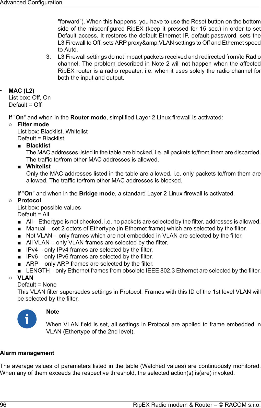
![A Short for Wi-Fi Protected Access 2 - Pre-Shared Key. It is a method of securing your networkusing WPA2 with the use of Pre-Shared Key (PSK) authentication. To encrypt a networkwith WPA2-PSK you provide your router not with an encryption key, but rather with a plain-English passphrase between 13 and 64 characters long. Using a technology called TKIP (forTemporal Key Integrity Protocol), that passphrase, along with the network SSID, is used togenerate unique encryption keys for each wireless client. And those encryption keys areconstantly changed.•WPA2 PSK Key - The string (13-64 characters) which is used for WPA2 encryption keygenerating.The following characters are not allowed in the key:" (Double quote)` (Grave accent)\ (Backslash)$ (Dollar symbol); (Semicolon)Neighbours&Statistics•ParametersList box: Default, ManualDefault = DefaultDefault – Default (recommended) values are set and can not be edited.Manual – Values can be set manually.There are 2 tables with diagnostic information in the main menu - Diagnostic/Neighbours, Diagnost-ic/Statistic. The Neighbours table displays Watched values from RipEX and from all its neighbours.(Neighbour = RipEX, which can be accessed directly over the radio channel, i.e. without a repeater).There is statistic information about the traffic volume in the Statistic table.○Watched values broadcasting period [min]Default = 120 min, [0 = Off]RipEX periodically broadcasts its Watched values to neighbouring units. The Watched valuescan be displayed in Graphs and Neighbours menu.Note: When Bridge mode is used, watched values broadcasting creates collisions for user traffic.Be careful in using this feature.○Neighbours&Statistic log save period [min]Default = 1440 min (1 day) [10 - 7200 min]This is the period, in which Neighbours and Statistics logs are saved in the archive and clearedand new logs start from the beginning.Note1: The history files are organized in a ring buffer. Whenever a new file is opened, thenumbers of files are shifted, i.e. 0->1, 1->2, etc. There is a history of 20 log files available.Note2: The Max value is 6.000.000 min. (more than 11 years) It used to be only 7.200 min. upto the 1.3.x.x fw version.Graphs•ParametersList box: Default, ManualDefault = DefaultDefault – Default (recommended) values are set and can't be edited.Manual – Values can be set manually.Graphs displays history of Watched values and history of some of the items from the Statistic table.Displayed values are stored in each RipEX including data from selected five neighbouring units.101© RACOM s.r.o. – RipEX Radio modem & RouterAdvanced Configuration](https://usermanual.wiki/Racom/RIPEX-215/User-Guide-2641538-Page-101.png)
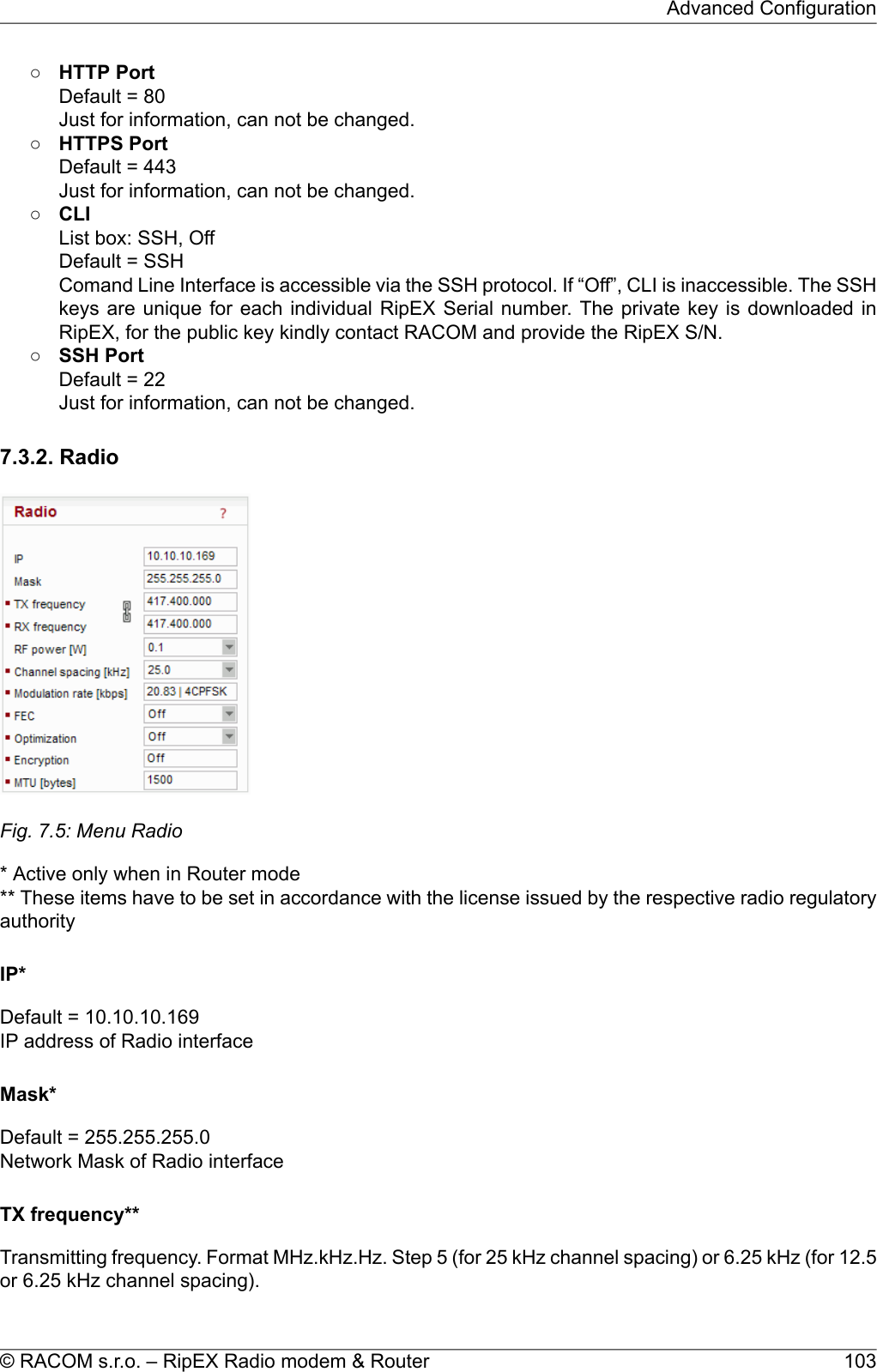
![The value entered must be within the frequency tuning range of the product as follows:RIPEX-135: 135–154 MHzRIPEX-154: 154–174 MHzRIPEX-215: 215–240 MHzRIPEX-300: 300–320 MHzRIPEX-320: 320–340 MHzRIPEX-340: 340–360 MHzRIPEX-368: 368–400 MHzRIPEX-400: 400–432 MHzRIPEX-432: 432–470 MHzRIPEX-470: 470–512 MHzRIPEX-928: 928–960 MHzRX frequency**Receiving frequency, the same format and rules apply.Note: By default, the TX and RX frequencies are locked together and change in one field is mirroredin the other. If clicked, the lock is removed and different TX and RX frequencies can be entered.Channel spacing [kHz]**List box: possible valuesDefault = 25 kHzThe wider the channel the higher the posible Modulation rate.Note: The 50 kHz channel spacing is available only for HW versions of Radio board higher than 1.1.90.0or 1.2.50.0. See Status/Radio/HW version.Modulation rate [kbps]**•ModeRipEX allows multiple settings of modulation parameters for every channel spacing to enablemeeting the different regulations which apply in different countries. Naturally different limits ontransmitted signal parameters result in different Modulation rates.The "Mode" menu conveniently groups the settings optimal for common internationally recognizedstandards. The detailed technical parameters for each setting can be found in the RipEX Usermanual.List box: possible valuesDefault = CE○CESettings optimized for ETSI standards and similar○FCCSettings suitable for countries which follow the U.S. government group of standards.Note: CPFSK modulations have approx. 20% higher frequency deviation compared to CE, sothe receiver sensitivity for the same modulation (data rate) is approx. 1-2 dB better.○NarrowSpecial settings for extra-restrictive regulations.Note: In the 25 kHz channel spacing, the RipEX transmitted signal 16kHz bandwidth contains99% of the total integrated power for transmitted spectrum according to ITU-R SM328 . Thissetting is required for 25 kHz channel spacing by authorities in Czech Republic.○UnlimitedRipEX Radio modem & Router – © RACOM s.r.o.104Advanced Configuration](https://usermanual.wiki/Racom/RIPEX-215/User-Guide-2641538-Page-104.png)
![Full channel width used to achieve the maximum possible data rate.•Modulation rate [kbps]List box: possible valuesDefault = 20.83 | 4CPFSKPossible values in list box are dependent on the Mode setting. The two highest rates for 25 and 50kHz channel spacing are available only when the corresponding SW feature key is active (Eitherthe 166/83 kbps key or the Master key).Higher Modulation rates provide higher data speeds but they also result in poorer receiver sensitivity,i.e. reduced coverage range. Reliability of communication over a radio channel is always higherwith lower Modulation rates.RF power [W]**List box: possible valuesDefault = 5 WThe range of values in the list box is limited to 2 W for high Modulation rates. 10 W is available onlyfor lower Modulation rates (CPFSK) and only when the corresponding SW feature key is active.Note: Max. RF power for RipEX-470 is 8 W. (Even if there was 10W in list box for fw ver. 1.3.x.x andolder)FECList box: possible valuesDefault = OffFEC (Forward Error Correction) is a very effective method to minimize radio channel impairments.Basically the sender inserts some redundant data into its messages. This redundancy allows the re-ceiver to detect and correct errors (to some extent). The improvement comes at the expense of theuser data rate. The lower the FEC ratio, the better the capability of error correction and the lower theuser data rate. The User data rate = Modulation rate x FEC ratio.Optimization*List box: On, OffDefault = OffOptimization is applicable in Router mode for packets directed to Radio channel. It watches packetson individual radio links and optimizes both the traffic to the counterpart of a link and the sharing of theRadio channel capacity among the links.On an individual link the optimizer supervises the traffic and it tries to join short packets when oppor-tunity comes. However in case of heavy load on one link (e.g. FTP download) it splits the continuousstream of packets and creates a window for the other links. To minimize the actual load, Zlib compression(with LZ77 decimation and Huffman coding) and other sophisticated methods are used.There is also a "stream" compression, which is very effective for data streams consisting of similarpackets. E.g. when there are many remotes behind a single repeater, packets on the most loaded hopbetween the repeater and the central unit get very efficiently compressed. Note: when there is onlyone direction traffic, there should be also routing for ETH IP addresses set in RipEX routing tables tomake stream compression effective.In addition a special TCP optimiser is used for TCP/IP connections. It supervises every TCP sessionand eliminates redundant packets. It also compresses TCP headers in a very efficient way. The overall105© RACOM s.r.o. – RipEX Radio modem & RouterAdvanced Configuration](https://usermanual.wiki/Racom/RIPEX-215/User-Guide-2641538-Page-105.png)
![effect of the Optimization depends on many factors (data content, packet lengths, network layout etc.),the total increase of network throughput can be anything from 0 to 200%, or even more in special cases.Note: Apart from this Optimization, there is an independent compression on the Radio channel, whichworks in both Operating modes, Bridge and Router. This compression is always On.EncryptionAES 256 (Advanced Encryption Standard) can be used to protect your data from an intrusion on Radiochannel. When AES 256 is On, control block of 16 Bytes length is attached to each frame on Radiochannel. AES requires an encryption key. The length of key is 256 bits (32 Bytes, 64 hexa chars). Thesame key must be stored in all units within the network.List box: Off, AES 256Default = OffWhen AES 256Key modeList box: Pass Phrase, ManualDefault = Pass Phrase•Pass phraseIt is not necessary to fill in 32 Bytes of hexa chars in order to set the encryption key. The key canbe automatically generated based on a Pass phrase. Fill in your Pass phrase (any printable ASCIIcharacter, min. 1 char., max. 128 char.). The same Pass phrase must be set in all units within thenetwork•ManualThe key can be configured manually (fill in 32 Bytes of 64 hexa chars) or it can be randomly generatedusing Generate button. The same key must be in all units within the network, i.e. it has to be gener-ated only in one unit and copied to the others.MTU [bytes]*Default = 1500 Bytes [70 - 1500] (max. packet size)When a packet to be transmitted from the Radio interface is longer than the MTU (Maximum Transmis-sion Unit) set, the RipEX router performs standard IP fragmentation. A packet longer than the configuredsize is split into the needed number of fragments, which are then independently transmitted - the firstpacket(s) is (are) transmitted fragment-size long, the last packet contains the remaining bytes. Thereassembly of the fragments into the original packet normally takes place in the unit at the end of thepath.Reducing the maximum length of a frame on a Radio link may improve its performance under unfavour-able conditions (interference, multi-path propagation effects). However the recommended place todetermine the packet size is the actual user interface, e.g. a COM port. Note that the IP fragmentingis possible in the Router mode only.7.3.3. ETH* Active only when Router modeRipEX Radio modem & Router – © RACOM s.r.o.106Advanced Configuration](https://usermanual.wiki/Racom/RIPEX-215/User-Guide-2641538-Page-106.png)
![•No of leasesDefault = 5 [1 - 255]Maximum number of DHCP client(s) which can RipEX simultaneously serve. It can not be morethan the number of addresses available in the Start IP - End IP range.•Lease timeout [DD:HH:MM:SS]Default = 1 day (max. 10 days)A DHCP Client has to ask DHCP Server for refresh of the received configuration within this timeout,otherwise the Lease expires and the same settings can be assigned to another device (MAC).•Assigned IP'sTable shows MAC addresses of Clients and IP addresses assigned to them by the Server. Expirationis the remaining time till the respective Lease expires. If the assigned IP addresses are required tobe deleted, set DHCP Server to Off, then action Apply and set DHCP server to On (+Apply) again.•Preferred IP'sIt is possible to define which IP should be assigned by the Server to a specific MAC. The requestedIP has to be within the Start IP – End IP range.Shaping*List box: On, OffDefault = OffEthernet interface could easily overload the Radio channel. Because of that, it is possible to shapetraffic received from the ETH interface.If On, specified volume of Data [Bytes] in specified Period [s] is allowed to enter the RipEX from ETHinterface. The first packet which exceeds the limit is stored in the buffer and transmitted when newPeriod starts. Further over-limit packets are discarded.SpeedList box: Auto, 100baseTX/Full, 100baseTX/Half, 10baseT/Full, 10baseT/HalfDefault = AutoCommunication speed on the Ethernet interface.Modbus TCP*Use this setttings only for Modbus TCP Master when it communicates with both types of Modbusslaves using either Modbus RTU or Modbus TCP protocols. Or when TCP/IP communication shouldrun locally between Modbus Master and RipEX in Modbus TCP network. Read Help and Applicationnote Modbus in RipEX.For more information refer to the manual Application note / Modbus TCP1.** - denotes items to be used only when either all or some RTUs (Remote Telemetry Unit) on remotesites are connected via RS232 or RS485 interface to RipEX, using the Modus RTU protocol. Thenautomatic conversion between Modbus TCP and Modbus RTU protocols takes place for such units.List box: On, OffDefault = Off•My TCP portDefault = 502 [1 - 65 535]TCP port used for Modbus TCP in RipEX.1http://www.racom.eu/eng/products/m/ripex/app/modbus.htmlRipEX Radio modem & Router – © RACOM s.r.o.108Advanced Configuration](https://usermanual.wiki/Racom/RIPEX-215/User-Guide-2641538-Page-108.png)
![•TCP Inactivity [s]Default = 120 [0 - 16 380]TCP socket in RipEX is kept active after the receipt of data for the set number of seconds.•Broadcast**List box: On, OffDefault = OffSome Master SCADA units send broadcast messages to all Slave units. SCADA application typicallyuses a specific address for such messages. RipEX (Protocol utility) converts such message to anIP broadcast and broadcasts it to all RipEX units resp. to all SCADA units within the network.If On, the address for broadcast packets in SCADA protocol has to be defined:•Broadcast address format - List box Hex, Dec - format in which broadcast address is defined.•Broadcast address - address in the defined format (Hex, Dec)•Address translationList box: Table, MaskDefault = MaskIn a SCADA protocol, each SCADA unit has a unique address, a "Protocol address". In RipEX Radionetwork, each SCADA unit is represented by an IP address (typically that of ETH interface) and aUDP port (that of the protocol daemon or the COM port server to which the SCADA device is con-nected via serial interface).A translation between "Protocol address" and the IP address & UDP port pair has to be done. Itcan be done either via Table or via Mask.Each SCADA message received from serial interface is encapsulated into a UDP/IP datagram,where destination IP address and destination UDP port are defined according the settings of Addresstranslation.○MaskTranslation using Mask is simpler to set, however it has some limitations:− all IP addresses used have to be within the same network, which is defined by this Mask− the same UDP port is used for all the SCADA units, which results in the following limitations:− SCADA devices on all sites have to be connected to the same interface (COM1 or COM2)− only one SCADA device to one COM port can be connected, even if the RS485 interface isused■Base IPDefault = IP address of ETH interfaceWhen the IP destination address of the UDP datagram, in which serial SCADA messagereceived from COM1(2) is encapsulated, is created, this Base IP is taken as the basis andonly the part defined by Mask is replaced by 'Protocol address'.■MaskDefault = 255.255.255.0A part of Base IP address defined by this Mask is replaced by 'Protocol address'. The SCADAprotocol address is typically 1 Byte, so Mask 255.255.255.0 is most frequently used.■UDP port (Interface)List box: COM1, COM2, TS1-TS5, TCPM1, Manual.Default = COM1This UDP port is used as the destination UDP port in the UDP datagram in which serialSCADA packet received from COM1(2) is encapsulated. Default UDP ports for COM1, COM2or Terminal servers 1-5 (TS1-TS5) or Modbus TCP (TCPM1) can be used or UDP port canbe set manually. If the destination IP address belongs to a RipEX and the UDP port is notassigned to COM1(2) or to a Terminal server or to any special daemon running in the destin-ation RipEX, the packet is discarded.○Table109© RACOM s.r.o. – RipEX Radio modem & RouterAdvanced Configuration](https://usermanual.wiki/Racom/RIPEX-215/User-Guide-2641538-Page-109.png)
![less be aware that any individual datagram can be lost. The locally run TCP sessionscannot guarantee 100% data integrity end-to-end.3. RipEX can handle up to 100 concurrent TCP proxy connections.List box: On, OffDefault = Off•TCP Inactivity [s]Default = 120Timeout in sec for which the TCP socket in RipEX is kept active after the last data reception ortransmission.•IPIP address or interval of IP addresses (e.g.: 192.168.20.20 – 192.168.20.26) for which the TCP/UDPconversion is done.0.0.0.0 means all IP addresses.•PortPort or interval of Ports (e.g.: 40100 – 40200), in conjunction with IP addresses in the same line,for which the TCP/UDP conversion is done.•DirectionDst – IP and Port as defined above are considered as Destination in the received packetSrc – IP and Port as defined above are considered as Source in the received packet•NoteYou may add a note to each address up to 16 characters long for your convenience. (E.g. “Remoteunit #1 etc.). Following characters are not allowed:" (Double quote)\ (Backslash)$ (Dollar symbol); (Semicolon)•ActiveYou may tick/untick each line in order to make it active/not active.•ModifyDelete and Add buttons allow to add or to delete a line. The lines can be sorted using up and downarrows.ARP proxy & VLAN•General description•ARP proxy (Router mode only)When a remote device connected over a Router-mode RipEX network does not support routing(i.e. the default gateway cannot be configured), the narrowest possible subnet should be configuredon the respective Eth interface of the RipEX connected to it and the ARP proxy switched on. TheRipEX then answers ARP requests for all IP addresses routed to its radio interface. Correspondingsettings can be used in the RipEX connected to the central application device, thus enabling therouted RipEX network to act as a direct (V)LAN connection for such devices.Beware! Whenever there is more than one IP device connected to a RipEX, or even more RipEXesconnected to the same physical Eth, the ARP proxy must be used with the utmost care!! Subnetsrouted to the radio interface must be reduced to the minimum necessary, default gateway shouldnever be used. Accidental unwanted ARP responses may destroy all communication in the con-nected LAN!•VLANRipEX Radio modem & Router – © RACOM s.r.o.112Advanced Configuration](https://usermanual.wiki/Racom/RIPEX-215/User-Guide-2641538-Page-112.png)
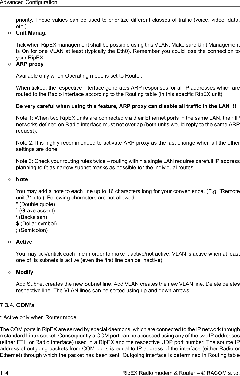
![according to the destination IP. The default UDP port numbers are COM1 = 8881, COM2 = 8882. Ifnecessary they may be changed using CLI, nevertheless it is recommended to stick to the default valuesbecause of dependencies between different settings (e.g. Protocols) in the network.ImportantUDP port settings is valid only in Router mode. In Bridge mode all packets received by COMport are broadcasted to all COM ports on all RipEXes within the network.Fig. 7.7: Menu COMTypeList box: possible valuesDefault = RS232COM1 is always RS232, COM2 can be configured to either RS232 or RS485.ImportantThe settings of Data rate, Data bits, Parity and Stop bits of COM port and connected devicemust match.Baud rate [bps]List box: standard series of rates from 300 to 115200 bpsDefault = 19200Select Baud rate from the list box: 300 to 115200 bps rates are available.Serial ports use two-level (binary) signaling, so the data rate in bits per second is equal to the symbolrate in baudsData bitsList box: 8, 7Default = 8The number of data bits in each character.ParityList box: None, Odd, Even115© RACOM s.r.o. – RipEX Radio modem & RouterAdvanced Configuration](https://usermanual.wiki/Racom/RIPEX-215/User-Guide-2641538-Page-115.png)
![Default = NoneWikipedia: Parity is a method of detecting errors in transmission. When parity is used with a serialport, an extra data bit is sent with each data character, arranged so that the number of 1-bits in eachcharacter, including the parity bit, is always odd or always even. If a byte is received with the wrongnumber of 1s, then it must have been corrupted. However, an even number of errors can pass theparity check.Stop bitsList box: possible valuesDefault = 1Wikipedia: Stop bits sent at the end of every character allow the receiving signal hardware to detectthe end of a character and to resynchronise with the character stream.Idle [bytes]Default = 5 [0 - 2000]This parameter defines the maximum gap (in bytes) in the received data stream. If the gap exceedsthe value set, the link is considered idle, the received frame is closed and forwarded to the network.MRU [bytes]Default = 1600 [1 - 1600]MRU (Maximum Reception Unit) — an incoming frame is closed at this size even if the stream of bytescontinues. Consequently, a permanent data stream coming to a COM results in a sequence of MRU-sized frames sent over the network.NoteVery long frames (>800 bytes) require good signal conditions on the Radio channeland the probability of a collision increases rapidly with the length of the frames. Hence1.if your application can work with smaller MTU, it is recommended to use values in 200– 400 bytes range.2. This MRU and the MTU in Radio settings are independent. However MTU should begreater or equal to MRU.Flow controlList box: None, RTS/CTSDefault = NoneRTS/CTS (Request To Send / Clear To Send) hardware flow control (handshake) between the DTE(Data Terminal Equipment) and RipEX (DCE - Data Communications Equipment) can be enabled inorder to pause and resume the transmission of data. If RX buffer of RipEX is full, the CTS goes down.Note: RTS/CTS Flow control requires a 5-wire connection to the COM port.Protocol*List box: possible valuesDefault = NoneEach SCADA protocol used on serial interface is more or less unique. The COM port daemon performsconversion to standard UDP datagrams used in RipEX Radio network. Each protocol has its individualRipEX Radio modem & Router – © RACOM s.r.o.116Advanced Configuration](https://usermanual.wiki/Racom/RIPEX-215/User-Guide-2641538-Page-116.png)
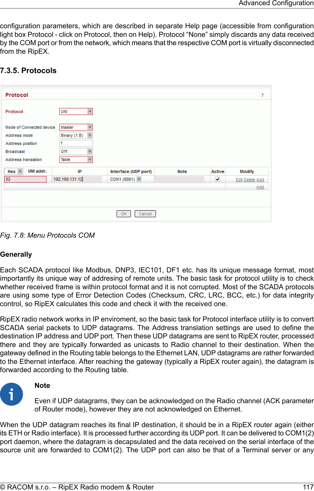
![SlaveBroadcast accept•Max gap timeout [ms]Default = 30The longest time gap for which a frame can be interrupted and still received successfully as oneframe. It should not be set below 10ms, while 15–40 ms should be OK for a typical Cactus protocoldevice.ComliComli is a serial polling-type communication protocol used by Master-Slave application.When RipEX radio network run in Router mode, more Comli Masters can be used within one Radionetwork and one Slave can be polled by more Masters.Broadcasts packets are not used, so the configuration is using only some parameters describedCommon parameters.Mode of Connected deviceMasterAddress translationTableMaskSlaveDF1Only the full duplex mode of DF1 is supported. Each frame in the Allen-Bradley DF1 protocol containsthe source and destination addresses in its header, so there is no difference between Master and Slavein the Full duplex mode in terms of RipEX configuration.•Block control modeList box: BCC, CRCDefault = BCCAccording to the DF1 specification, either BCC or CRC for Block control mode (data integrity) canbe used.•BroadcastAccording to the DF1 specification, packets for the destination address 0xFF are consideredbroadcasts. Hence when Broadcast is On, packets with this destination are handled as broadcasts.Address translationTableMask•Advanced parameters○ACK LocallyList box: Off, OnDefault = OnIf "On", ACK frames (0x1006)are not transferred over-the-air.When the RipEX receives a data frame from the connected device, it generates the ACK frame(0x1006) locally. When the RipEX receives the data frame from the Radio channel, it sends theRipEX Radio modem & Router – © RACOM s.r.o.122Advanced Configuration](https://usermanual.wiki/Racom/RIPEX-215/User-Guide-2641538-Page-122.png)
![Broadcast from Master station is generated when address byte is 0x00.■SINAUTThe sequence of Address byte and Control byte in the frame is changed-over.Broadcast from Master station is generated when address byte is 0x00.ITT FlygtITT Flygt is a serial polling-type communication protocol used in Master-Slave applications.ITT Flygt protocol configuration uses all parameters described in Common parameters.Mode of Connected deviceMasterBroadcastNote: There is not a possibility to set the Broadcast address, since ITTFlygt broadcast messages always have the address 0xFFFF. Hence whenthe Broadcast is On, packets with this destination are handled as broad-casts.•First Slave AddressDefault = 1Slave addresses are not defined in the ITT Flygt protocol. HoweverSlave addresses have to be defined in the RipEX network. This is theFirst Slave address in decimal format.•Number of SlavesDefault = 1Since the ITT Flygt protocol Master (centre) polls the Slaves (remotes)one by one without any addressing, number of slaves has to be defined.Address translationTableMaskSlaveBroadcast accept•Wait timeout [ms]Default = 5000An ITT Flygt Slave sometimes sends the WAIT COMMAND (0x13) to its Master. The RipEX doesnot accept the next WAIT COMMAND (discards it), till the Wait timeout does not expire. The Re-commended value is in the 1-10 seconds range.ModbusModbus RTU is a serial polling-type communication protocol used by Master-Slave application.When RipEX radio network run in Router mode, more Modbus Masters can be used within one Radionetwork and one Slave can be polled by more Masters.Modbus protocol configuration uses all parameters described in Common parameters.Mode of Connected deviceMasterRipEX Radio modem & Router – © RACOM s.r.o.124Advanced Configuration](https://usermanual.wiki/Racom/RIPEX-215/User-Guide-2641538-Page-124.png)
![slave is out of order, the central RipEX stops local answering to RB packets from the master for therespective slave.•RB Net period [s]Default = 10The RipEX responds to the RB packets locally and in the set RB period the RB packets are trans-ferred over the network.•RB Net timeout [s]Default = 10 (maximum=8190)Whenever an RB packet is sent over the network, the set RB Net timeout starts. When the RB re-sponse from the remote unit (slave) is not received within the timeout, i.e. the respective slave isout of order, the central RipEX stops the local answering to RB packets from the master for the re-spective slave.Address translationTableMaskSlaveSlave•Local simulation RBList box: Off, OnDefault = OffThe RP570 Slave expects to receive RB packets from the Master. When the Local simulation RBon the Master is On, the RB packets are transferred over the Radio channel only in the RB Netperiod (see Master settings). The Local simulation RB has to be set the same (On or Off) on allsites in the network, i.e. on the master as well as all slaves.If On, the RipEX generates RB packets locally and transmits them over the COM interface in theRB Request period and expects the RB response for each RB packet from the RP570 Slave withinthe RB Response timeout. When the RipEX does not receive the response(s) from the RP570 slave,the RipEX does not respond to the RB packet from the Master which it receives over the Radiochannel.•RB Request period [ms]Default = 200 (maximum=8190)RipEX sends locally RB packets to the connected RTU in the set period.•RB Response timeout [ms]Default = 500 (maximum=8190)The RipEX expects a response to the RB packet within the set timeout. If it is not received, theRipEX does not respond to RB packets from the Master received over the Radio channel.•RTU address (Hex)Default = 01Active only when the Local simulation RB is On. The connected RTU’s address is supposed to befilled in. This address (0x00-0xFF) is used in the RB packets generated locally in the RipEX andtransmitted over the COM.RipEX Radio modem & Router – © RACOM s.r.o.126Advanced Configuration](https://usermanual.wiki/Racom/RIPEX-215/User-Guide-2641538-Page-126.png)
![Siemens 3964(R)The 3964 protocol is utilized by the Siemens Company as a Point-to-Point connection between twocontrollers. Meanwhile it has developed into an industry standard that can be found on many devicesas a universal communications interface. 3964R is the same as 3964, in addition it only uses BCC(Block Check Character). 3964(R) handles only the link layer (L2 in OSI model), hence RipEX uses asimilar way to read “SCADA address” as in UNI protocol.There is a handshake STX(0x02) – DLE(Ox10) on the start of communication and DLE+ETX – DLEon the end. This handshake is performed by RipEX locally, it is not transferred over the RipEX network.Communication goes as follows:LocalRTU->STX->LocalRipexLocalRipex->DLE->LocalRTULocalRTU->DATA+DLE+ETX+BCC->LocalRipexLocalRipex->DATA->RemoteRipex*LocalRipex->DLE->LocalRTURemoteRipex->STX->RemoteRTURemoteRTU->DLE->RemoteRipexRemoteRipex->DATA+DLE+ETX+BCC->RemoteRTURemoteRTU->DLE->RemoteRipex* only this packet is transferred over the RipEX network, all the other ones are handled locally.Underlined parameters are described in Common parameters.Mode of Connected deviceMaster•Address modeList box: Binary (1 B), Binary (2B LSB first). Binary (2B MSB first).Default = Binary (1 B)RipEX reads the Protocol address in the format and length set (in Bytes).•Address positionSpecify the sequence number of the byte, where the Protocol addressstarts.Note 1: 3964(R) protocol is using escape sequence (control sequence)for DLE(0x10). I.e. when 0x10 is in user data, 0x1010 is sent instead.When address position is calculated, the bytes added by escape se-quence algorithm are not taken into account.Note 2: The first byte in the packet has the sequence number 1, not 0.BroadcastAddress translationTableMaskSlaveBroadcast accept•DLE timeout [ms]127© RACOM s.r.o. – RipEX Radio modem & RouterAdvanced Configuration](https://usermanual.wiki/Racom/RIPEX-215/User-Guide-2641538-Page-127.png)
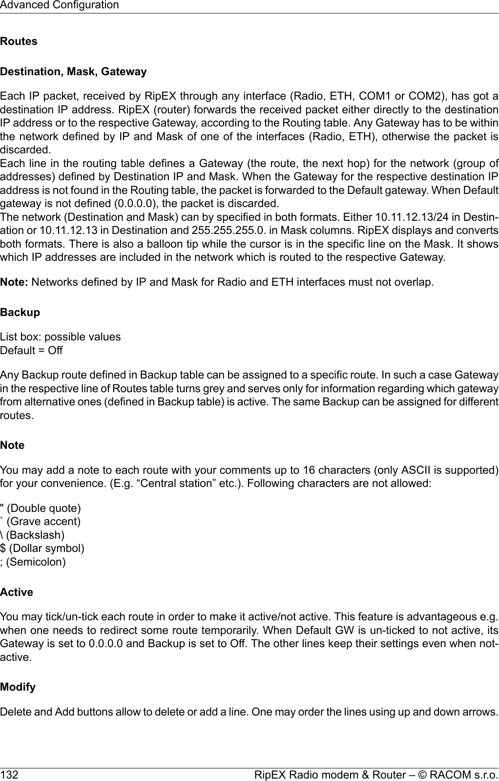
![Default = 1000 (min. 300, max. 8190)RipEX expects a response (DLE) from the connected device (RTU) within the set timeout. If it isnot received, RipEX repeats the frame according to the “Retries” setting.•Retries [No]Default = 3 (min. 0, max. 7)When DLE timeout is „On“, and DLE packet is not received from the connected device (RTU)within the set DLE timeout, RipEX retransmits the frame. The number of possible retries is specified.•PriorityList box: Low, HighDefault = LowWhen the equipment sends STX and receives STX instead of DLE, there is a collision, bothequipments want to start communication. In such a case, one unit has to have a priority. If the Pri-ority is High, RipEX waits for DLE. When it is Low, RipEX send DLE.Note: Obviously, two pieces of equipment which are communicating together must be set so thatone has High priority and the other has Low.•BCCList box: On, OffDefault = OnBCC (Block Check Character) is a control byte used for data integrity control, it makes the reliabilityhigher. BCC is used by 3964R, 3964 does not use it.RipEX checks (calculates itself) this byte while receiving a packet on COM. RipEX transmits DLE(accepts the frame) only when the check result is OK. BCC byte is not transferred over the RipEXnetwork, it is calculated locally in the end RipEX and appended to the received data.SLIPSLIP (Serial Line Internet Protocol) allows the Internet Protocol3(IP), normally used on Ethernet4, tobe used over a serial line5. SLIP modifies a standard IP packet by prepending and appending a specialSLIP END character to it, which allows packets to be distinguished as separate. SLIP requires a COMport configuration of 8 data bits, no parity6and flow control7. SLIP does not provide error detection8,being reliant on other high-layer protocols for this. A SLIP connection needs to have its IP address9configuration set each time before it is established.•Local IPIP address assigned to COM port (local point of SLIP protocol) used for p-t-p communication withConnected device. It has to be within the subnet defined by Peer IP and Peer IP mask.•Peer IPThis is IP address of Connected device (remote point of SLIP protocol) on the other end of RS232.•Peer IP maskPeer IP and Peer IP mask defines Subnet, which is routed into SLIP on respective COM.3http://dictionary.reference.com/browse/Internet%20Protocol4http://dictionary.reference.com/browse/Ethernet5http://dictionary.reference.com/browse/serial%20line6http://dictionary.reference.com/browse/parity7http://dictionary.reference.com/browse/hardware%20flow%20control8http://dictionary.reference.com/browse/error%20detection9http://dictionary.reference.com/browse/IP%20addressRipEX Radio modem & Router – © RACOM s.r.o.128Advanced Configuration](https://usermanual.wiki/Racom/RIPEX-215/User-Guide-2641538-Page-128.png)
![BackupRipEX is capable to test path between two RipEX IP addresses (even behind a repeater or LAN). Whenthe connection fails, RipEX automatically uses alternative gateway(s) defined in the Alternative pathscolumn with the priority according to the line sequence. The system always tries to use the route withthe highest priority, e.g. automatically switches back when the failed route starts to work.Hello packets are used for path testing. Each direction (back and forth) is tested independently, i.e. therouting can be non-symmetrical. Data in the transmitted Hello packet carry the information about receivedHello packets from the counterpart (Peer IP). The path is evaluated as the good one, when Hellopackets from counterpart (carried the info, that counterpart successfully received „my” Hello packets)are received. i.e. each side decides itself which outbound route (gateway) will be used.Backup path status is displayed: Up – green background, Down – red background, Unknown – yellowbackground, Currently used – bold.•NameYou can name Backup path as per your choice. The name can be up to 16 characters long for yourconvenience. (E.g. “Remote unit #1 etc.). Following characters are not allowed:" (Double quote)` (Grave accent)\ (Backslash)$ (Dollar symbol); (Semicolon)•Hysteresis [s]Alterative path is kept for the time set in order to avoid chaotic switching among different paths underunstable conditions.•SNMP TrapWhen ticked, SNMP Trap is sent whenever there is a change in the path status: Up, Down, Unknown,Currently used.•Peer IPIP address of the RipEX (either its Radio or Ethernet interface) on the remote end of the Backuppath (Hello packet is sent there). Only RipEX IP of Radio or the main Ethernet interface can beused, no Subnets.Note: Do not forget to set correct routing to „Peer IP“ for Hello packets.•GatewayMore Gateways (alternatives) can be defined for one Backup path. When the path using the first(highest priority) Gateway fails, the next one (defined on the next line) is automatically used. Gatewaydisplayed in Bold is currently used.•PolicyPolicy defines the conditions for switching to the alternative gateway.•ParametersList box: Default, Manual,Default = Default•Default – Default (recommended) values are set and can not be edited.•Manual – Values can be set manually.○Hello packet period [s]Default = 60 sec, [Max=3600]When the set period expires, the next Hello packet is transmitted. To avoid the collisions, thereis a jitter of approx. 5%.○Hello packet success rate [%]133© RACOM s.r.o. – RipEX Radio modem & RouterAdvanced Configuration](https://usermanual.wiki/Racom/RIPEX-215/User-Guide-2641538-Page-133.png)
![List box: possible valuesDefault = 87.5When a lower percentage of Hello packets than set has been delivered to the counterpart, theunit switches to the next alternative gateway in the line. (The info about successfully deliveredoutbound Hello packets are carried by received Hello packets)○RSS [-dBm]Default = Off [255= Off]Hello packets carry the info about average RSS (saved in respective Statistic table) on eachradio hop on its way. When any RSS on the way is lower than the set one, the unit switches tothe next alternative gateway in the line. Each individual packet is evaluated.○Lower priority paths checkingList box: On/OffDefault = OnIf On, all alternative routes are checked, including the lower priority ones (Hello packets aretransmitted). Advantage – if active route fails, system switches only to functional alternative.Disadvantage – when e.g. GSM for backup is used, Hello packets used for testing are charged.Routes with a higher priority than the active one are always tested.Note 1: the number of Backup paths is not limited. The number of Alternative routes is min.2 and max.16 (active ones). There can be more than 16 Alternative routes defined, only active ones are checked.Note 2: When Optimization (Settings/Radio/Optimization) is “On”, UDP packets with both source anddestination port 8886 are not transferred over the network, they are discarded in end RipEX. UDPpackets with source port 8903 are not optimized, even if Optimization is “On”.Note 3: When SW key Backup routes or Master key expires, Backup path configuration is lost.Buttons•Apply - applies and saves the changes.•Cancel - restores original values.•Find - finds (highlights the respective line in the table) the route for a specific IP address if exists.•Check routing - highlights duplicate routes for specific IP if they exist.•Backup status - refresh the status of backup routes (Good, Failure, Unknown, Currently used)RipEX Radio modem & Router – © RACOM s.r.o.134Advanced Configuration](https://usermanual.wiki/Racom/RIPEX-215/User-Guide-2641538-Page-134.png)
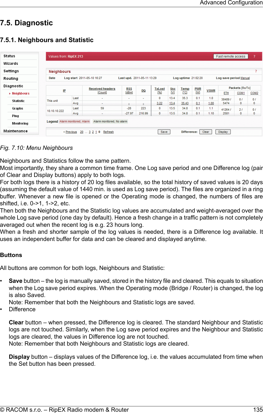
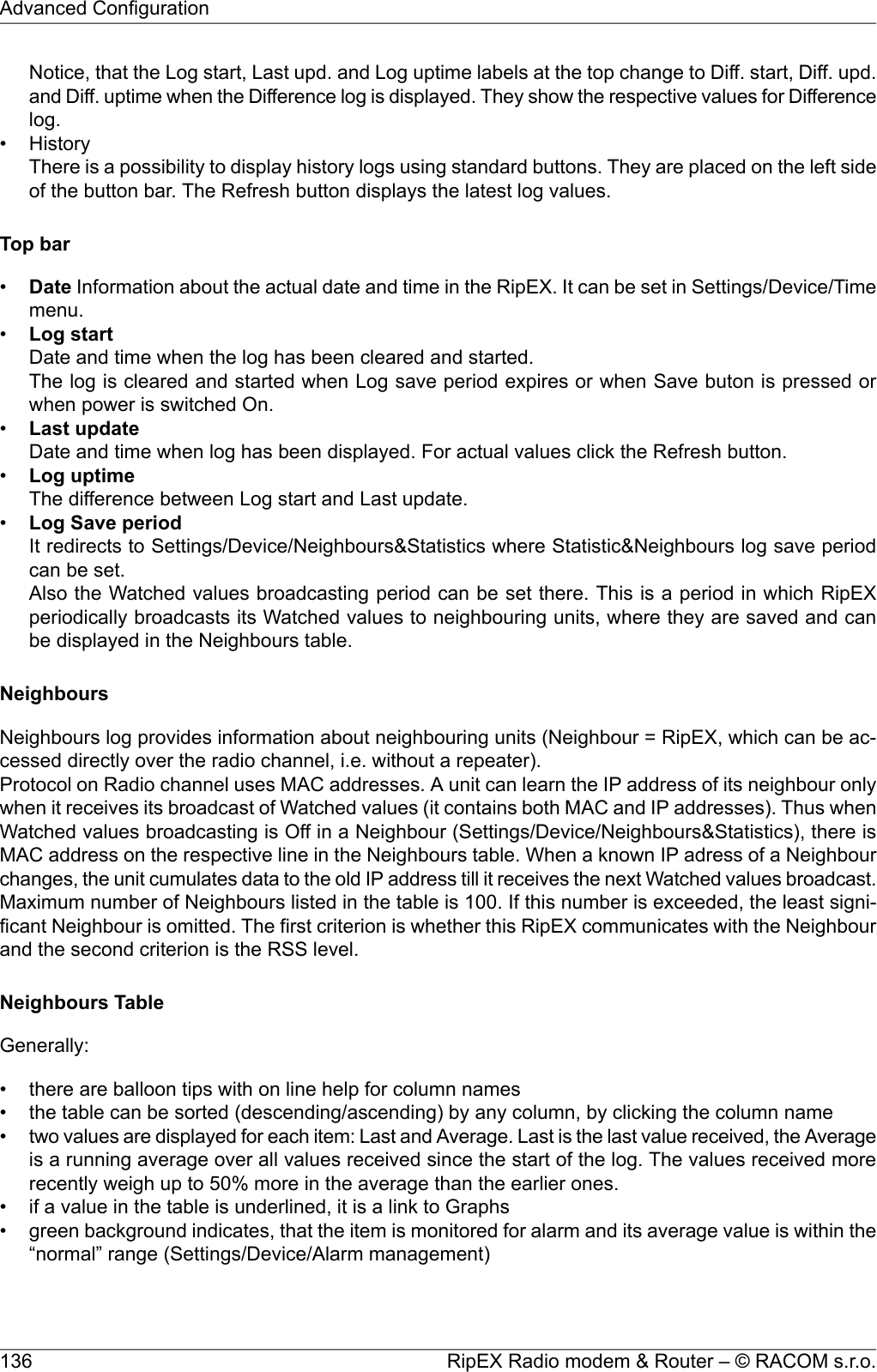
![• red background indicates, that the item is monitored for alarm and its average value is in the alarmrange (Settings/Device/Alarm management)• when the value of RSS, DQ, Ucc, Temp, PWR, VSWR is not known, N/A is displayed. These N/Avalues are not displayed in Graphs•Ucc, Temp, PWR, VSWR are refreshed every 1s. The other values in both, Neighbours and Statisticstables are refreshed every 20s• IP addresses:○Bridge modeDue to broadcast pattern of traffic in Radio channel, all frames generated by user application(s)cumulate in one line in the Neighbour table. When diagnostic or service frames (e.g. Watchedvalues) are transmitted in the network, they are listed in separate lines, distinguished by IP ad-dress of their respective Ethernet interfaces.○Router modeMAC addresses of Radio interface are used for link layer communication on Radio channel.When RipEX knows the IP address corresponding with the MAC address (the IP has been thedestination IP of a packet transferred), IP address is displayed. If the IP address is not known,the MAC address is displayed.The first three columns are logged by the receiving RipEX itself.○Received headers [Count]Total number of frame headers received from the respective RipEX.○RSS [dBm]Received Signal Strength.○DQData Quality of received frames. The DQ value is about proportional to BER (bit error ratio) andabout independent of the data rate and modulation used. Consequently when data rate is lowered,the DQ value increases and the other way round. Judging the DQ values requires experience,rule-of-thumb figures are as followsvalues: DQ below 100 means the link is unusable, aroundt125 short packets starthould getting through, about 160 and above can be considered “good”values.The remaining columns contain values broadcasted by neighbouring units in their Watched valuesbroadcasting periods(Settings/Device/Neighbours&Statistics).○TxLost [%]The probability of a transmitted frame being lost (100 * Lost frames / All transmitted frames).This value is broadcasted only when Router mode is used and ACK is On.○Ucc [V]Power voltage measured on power input.○Temp [°C]Temperature inside of the RipEX.○PWR [W]The actual value of Radio output power measured by RipEX itself.○VSWRVoltage Standing Wave Ratio (1.0=best, 1.0–1.8=acceptable, >2.5=indicates a serious problemin antenna or feeder)○Packets [Rx/Tx]The total number of packets received from / transmitted to ETH, COM1, COM2 interfaces.Can be used for interface activity diagnostic.137© RACOM s.r.o. – RipEX Radio modem & RouterAdvanced Configuration](https://usermanual.wiki/Racom/RIPEX-215/User-Guide-2641538-Page-137.png)
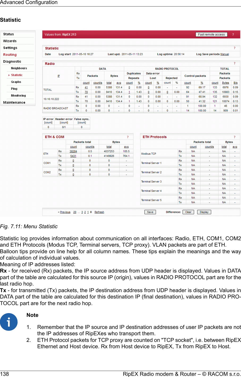
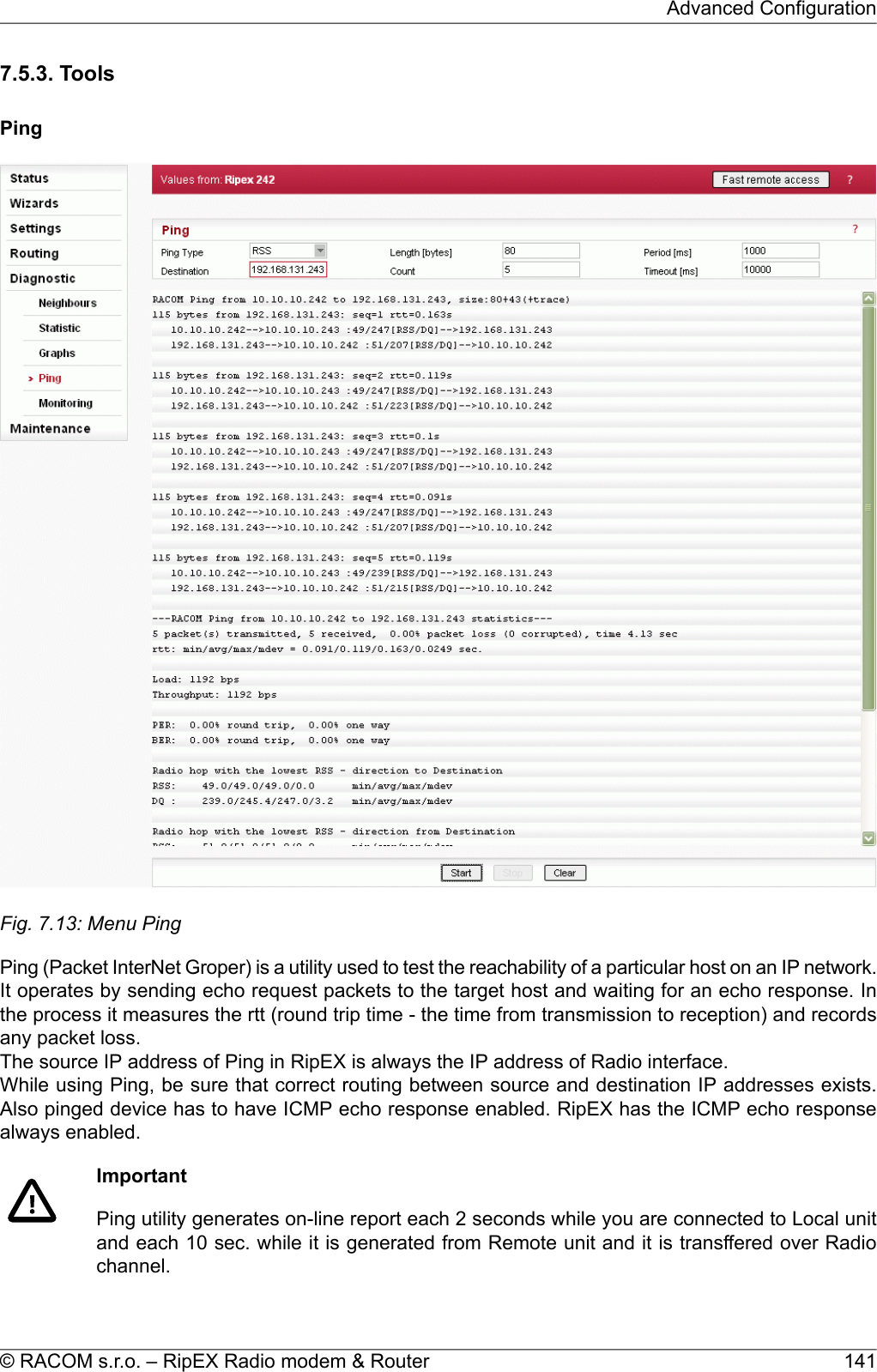
![■Ping TypeList box: ICMP, RSSDefault = RSS○ICMPThis is a standard ICMP (Internet Control Message Protocol) ping. It can be used against eitherRipEX or any device connected to RipEX Radio network.○RSSRSS Ping Type uses a special UDP packets and provides extension report which includes:• RSS and DQ information for each radio hop for each individual ping•RSS and DQ statistic (average, min., max.) for radio hop with the lowest RSS in both directions• Histogram of rtt of pings divided to 5 intervals• Load and Throughput• PER (Packet Error Rate)• BER (Bit Error Rate)■DestinationDefault = 127.0.0.1Destination IP address■Length [bytes]Default = 80The length of user data, the range from 8 to 4096 Byte. Some overhead to this Length is alwaysadded like these:ICMP - 28 bytesRSS - 43 bytes for IP+UDP+RACOM header + 8 bytes (Trace-RSS and DQ) per each radio hop +4 bytes (marking in server)RSS ping can not be longer than 3/4 MTU.■CountDefault = 5Number of pings to be transmitted. The allowed range is from 1 to 1024.■Period [ms]Default = 1000When this Period expires, the next Ping is transmitted. The range is from 1000 (1 sec.) to 3600000(1 hour).■Timeout [ms]Default = 10000Timeout from 1000 (1 sec.) to 3600000 (1 hour).When ping (the response) is not received within this timeout, it is counted as lost.■ReportA short report is generated in run-time for each individual ping packet. When the Ping utility isstopped, an overall statistic report is displayed.○ICMPStandard Linux ping reports are provided:•Run-time report:"88 bytes from 192.168.131.243: icmp_req=1 ttl=63 time=360 ms"88 bytes = total packet lenght192.168.131.243 = destination IPicmp_req = ping sequence numberttl = time to live, max. number of hops (passing through router) of the packet in the networkRipEX Radio modem & Router – © RACOM s.r.o.142Advanced Configuration](https://usermanual.wiki/Racom/RIPEX-215/User-Guide-2641538-Page-142.png)
![time = rtt (round trip time), the time from transmission of ICMP echo request to reception ofICMP echo response•Statistic report:"5 packets transmitted, 5 received, 0% packet loss, time 4002ms""rtt min/avg/max/mdev = 327.229/377.519/462.590/45.516 ms"time = total time of ping utility (From Start to Stop buttons)rtt min/avg/max/mdev = round trip time, minimal/average/maximal/standard deviation○RSS•Run-time report:"131 bytes from 192.168.131.243: seq=1 rtt=0.805s""10.10.10.241-->10.10.10.242 :56/209[RSS/DQ]-->10.10.10.243:51/225[RSS/DQ]-->192.168.131.243""192.168.131.243-->10.10.10.242 :46/214[RSS/DQ]-->10.10.10.241 :57/213[RSS/DQ]-->10.10.10.241"131 bytes = RSS packet size (RACOM header + data + trace)10.10.10.242 = repeater IP192.168.131.243 = destination IPseq = ping sequence numberrtt = round trip time, the time from transmission to reception•Statistic report:"5 packet(s) transmitted, 5 received, 0.00% packet loss (0 corrupted), time 4.48 sec""rtt: min/avg/max/mdev = 0.371/0.483/0.805/0.166 sec."corrupted = number of packets which have been received (UDP header is OK) neverthelesstheir data have been corrupted (CRC over data is not OK)time = the total time of ping utility (From Start to Stop buttons)rtt min/avg/max/mdev = round trip time, minimal/average/maximal/standard deviation"Load: 1098 bps""Throughput: 1098 bps"Load = the load generated by Ping utilityThroughput = the througput provided by Radio network"PER: 0.00% round trip, 0.00% one-way""BER: 0.00% round trip, 0.00% one-way"PER - Packet Error Rate, i.e. the probability of a packet being lost. It is calculated for boththe whole round trip and a one-way trip.BER - Bit Error Rate, the probability of one bit received with incorrect value. Only packets,no bits can be lost in packet radio network. When a single bit is received wrong, the wholepacket is lost. The BER is calculated from the PER based on this assumption."Radio hop with lowest RSS – direction to Destination""RSS: 56.0/56.8/58.0/0.7 min/avg/max/mdev""DQ : 208.0/219.0/232.0/9.4 min/avg/max/mdev""Radio hop with lowest RSS – direction from Destination""RSS: 56.0/56.4/57.0/0.5 min/avg/max/mdev""DQ : 208.0/216.2/223.0/5.3 min/avg/max/mdev"There is RSS (Received Signal Strenght) and DQ (Data Quality) information from the radiohop with lowest RSS, separately for both directions (To and From the destination RipEX).The mdev values for both the RSS and DQ are provided, giving idea on signal homogeneity.The lower values are recorded, the more reliable the link should be. The “Homogenity” showsthe jitter of RSS values from individual pings.143© RACOM s.r.o. – RipEX Radio modem & RouterAdvanced Configuration](https://usermanual.wiki/Racom/RIPEX-215/User-Guide-2641538-Page-143.png)
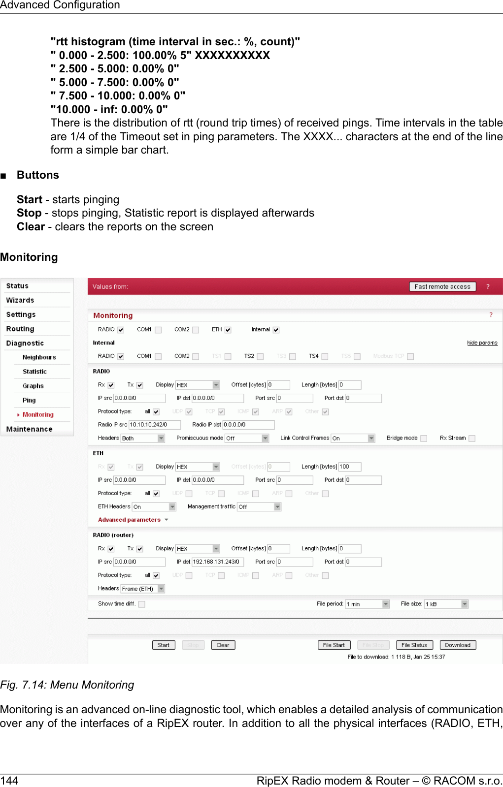
![COM1, COM2), some internal interfaces between software modules can be monitored when such ad-vanced diagnostics is needed.Monitoring output can be viewed on-line or saved to a file in the RipEX (e.g. a remote RipEX) anddownloaded later.Description of internal interfaces can be found below.■InterfacesTick boxes:RADIO, COM1, COM2, ETH, InternalWhen ticked, the setting for the respective interface(s) is enabled. When the "Internal" interface isticked, another set of interface tick-boxes appears as follows:Internal:RADIO, COM1, COM2, TS1, TS2, TS3, TS4, TS5, Modbus TCP, TCP proxyWhen ticked, the setting for the respective internal interface(s) is enabled (see the description below).■Common parameters for all interfaces:○Rx TxTick boxes.When ticked, packets (frames, messages) coming in the respective direction are monitored. Apacket is considered a Tx one when it comes out from the respective software module (e.g.RADIO or Terminal Server) and vice versa. When an external interface (e.g. COM:phy) ismonitored, the Tx also means packets being transmitted from the RipEX over the respectiveinterface (Rx means "received"). Understanding the directions over the internal interfaces maynot be that straightforward, please consult the diagram below for clarification.Please note the separate monitoring of Rx or Tx frames is not possible at the ETH interface.○DisplayList box: HEX, HEX+ASCII, ASCIIDefault = HEXThe format of monitoring output.○Offset [bytes]Default = 0Number of bytes from the beginning of packet/frame, which will not be displayed. The Lengthof bytes will be displayed starting from the immediately next byte.This feature is not available at the ETH interface.○Length [bytes]Default = 100Number of bytes, which will be displayed from each packet/frame.Example: Offset=2, Length=4 means, that bytes from the 3rd byte to the 6th (inclusive) will bedisplayed:Data (HEX): 01AB3798A28593CD6B96Monitoring output: ... 3798A285 ...■Filter parameters for IP/ARP packets(available for RADIO, ETH and Internal RADIO (router), COMn(router), TSn(router), ModbusTCP(router), TCP proxy (TCP), TCP proxy(router)):○IP srcIP source address range in the following format: aaa.bbb.ccc.ddd/mask145© RACOM s.r.o. – RipEX Radio modem & RouterAdvanced Configuration](https://usermanual.wiki/Racom/RIPEX-215/User-Guide-2641538-Page-145.png)
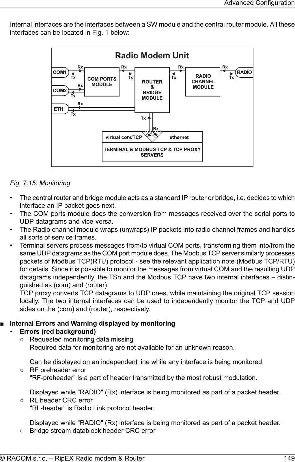
!["Bridge stream DB-header" is header of Data block transmitted while Operating mode isBridge and Frame closing (COM's) is Stream.Displayed while "RADIO" (Rx) interface is monitored as part of a packet header.○ Data CRC errorData CRC error.Displayed while "RADIO" (Rx) interface is monitored as part of a packet header.•Warnings (yellow background)○ Record sequence problem – reconfiguration?There is a problem in sequence of records. The system may have to be reconfigured withother Settings or Routing pages.Can be displayed on an independent line while any interface is being monitored.○ Record sequence problem. Some records may be lost.There is a problem in sequence of records for an unknown reason. One or more recordshave been lost.Can be displayed on an independent line while any interface is being monitored.○ [x] missing record(s) detected'x' (replaced by specific number) records are missing.Can be displayed on an independent line while any interface is being monitored.○ Monitoring restarted. Some records may be lost.Monitoring system has been restarted e.g. because of monitoring configuration change.Some records may be lost.Can be displayed on an independent line while any interface is being monitored.○ ETH monitoring terminated. Invalid tcpdump parameters?Monitoring of ETH interface has been stopped. Probably because of unsupported or wrong'tcpdump' syntax in Monitoring/ETH/Advanced parameters/User rule.Can be displayed on an independent line while ETH interface is being monitored○ Interface not ready!RF interface is not ready. May happen when system is booting, after reconfiguration, afterradio part recalibration made automatically after some time etc. The packet is discarded.Displayed while "Internal-RADIO" (Tx) interface is being monitored as part of a packetheader.○ RF interface not ready!Monitoring of ETH interface has been stopped. Probably because of unsupported or wrong'tcpdump' syntax in Monitoring/ETH/Advanced parameters/User rule.Can be displayed on an independent line while ETH interface is being monitored○ Interface not ready - high radio board temperature!The transmitting is blocked because radio board has reached a temperature higher than 95°C.Displayed while "RADIO" (Tx) interface is being monitored as part of a packet header.○ RF interface not ready - high radio board temperature!The transmitting is blocked because radio board has reached a temperature higher than 95°C.RipEX Radio modem & Router – © RACOM s.r.o.150Advanced Configuration](https://usermanual.wiki/Racom/RIPEX-215/User-Guide-2641538-Page-150.png)
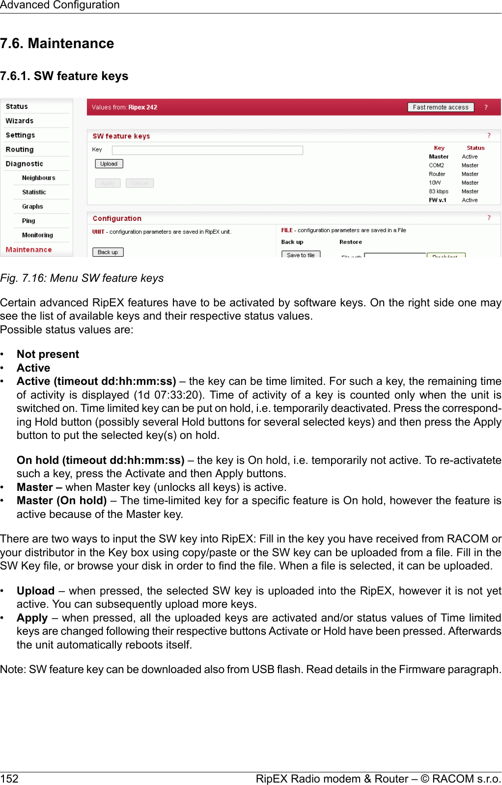
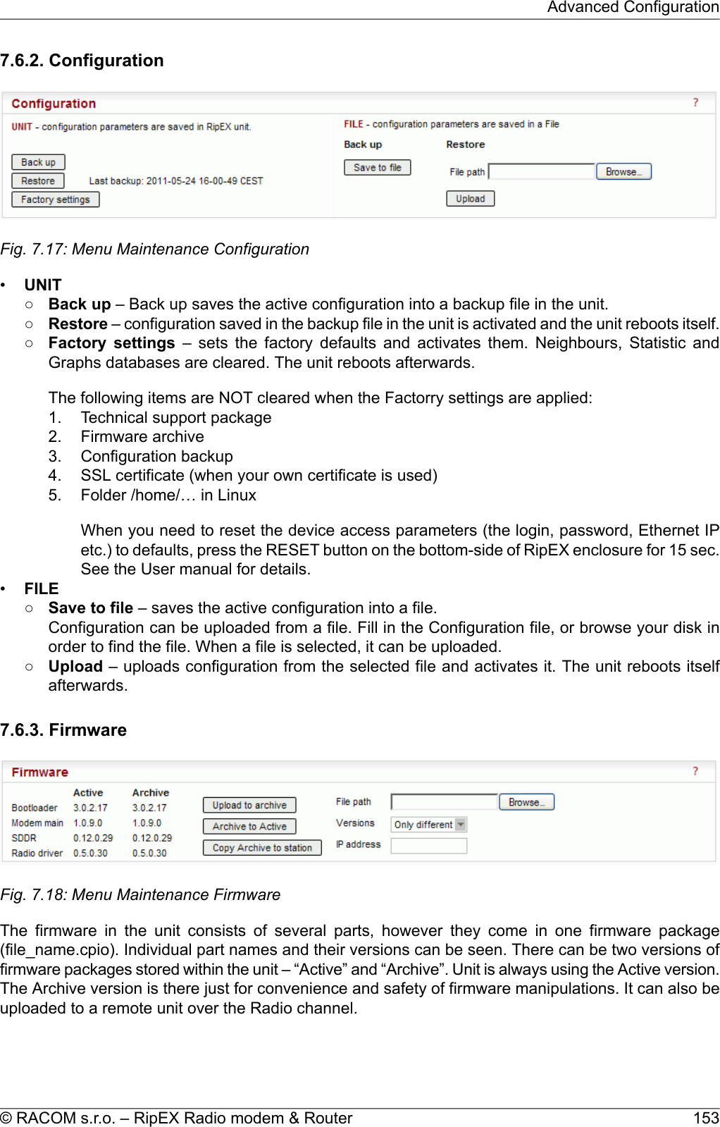
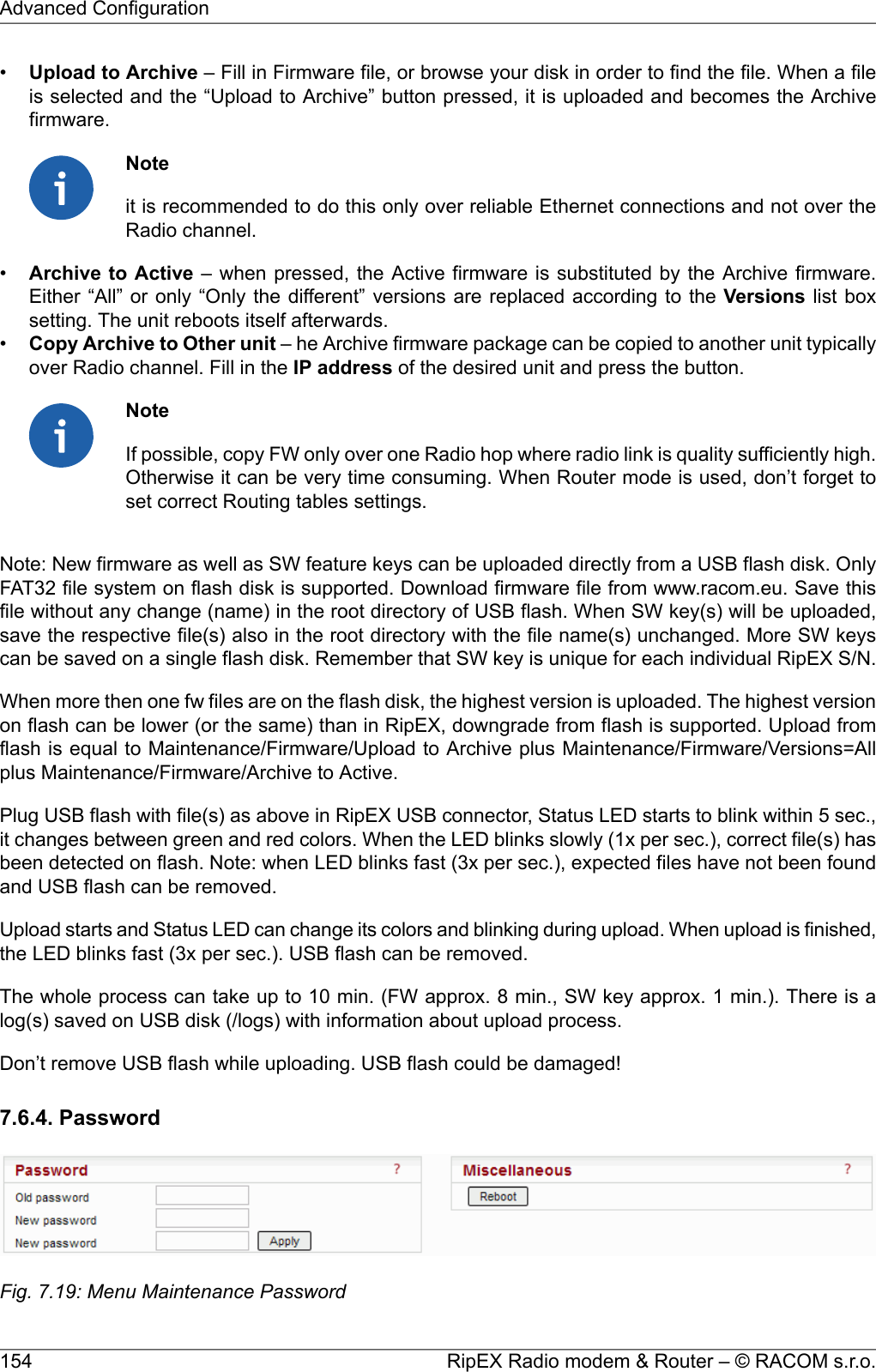
![It is highly recommended to change default password (admin) even if the user name remains alwaysthe same (admin). When the Apply button is pressed, the unit reboots.7.6.5. Miscellaneous•Reboot – when pressed, the unit correctly shuts down and starts again (performs the cold startwhich equals to a power cycle). The reboot time is approx. 25 sec.•BRC Radio MAC – when pressed, an ARP reply packet is broadcasted over the Radio channel.When e.g. a RipEX unit has been replaced by a spare one with the same Radio IP, but differentRadio MAC address, the neighbouring RipEXes update their ARP tables only after their respectivetimeout expires. Forced transmission of an ARP reply restores the communication with the neigboursimmediatelly.Note: The ARP reply packet is automatically transmitted after every boot, hence the manual invocationshould not be necessary. Nevertheless broadcasting an extra ARP reply following any IP or MAC addresschange is a good and recommended practice.7.6.6. SSL certificateIt is possible to download your own SSL certificate into RipEX for https communication used for webconfiguration. 2048 bits certificate is supported and recommended, however the 512 or 1024 bits certi-ficates can also be used. SSL certificate may have one or two files. Both options are supported.•Certificate fileFill in the Certificate file, or browse your disk in order to find the file.•Key fileWhen your SSL certificate consists of two files, fill in the Key file, or browse your disk in order to findthe file.When file(s) is selected, it can be uploaded.•Upload – when pressed, the selected Certificate is uploaded into the RipEX, however it is not activeyet.•Apply – when pressed, the uploaded certificate is activated. Afterwards the unit automatically rebootsitself.•Default – when pressed, the default RACOM SSL certificate is uploaded. To be activated, Applybutton has to be executed.7.6.7. RF transmission testIt is intended to be used for laboratory measurements or antenna testing.•TypeList box: Carrier, Random dataCarrier – only unmodulated carrier is transmittedRandom data – modulated random data is transmittedDefault = Carrier•Period [s]Default = 15 s (possible values 1s – 50s)During this time period RipEX transmits after Start button is executed.155© RACOM s.r.o. – RipEX Radio modem & RouterAdvanced Configuration](https://usermanual.wiki/Racom/RIPEX-215/User-Guide-2641538-Page-155.png)
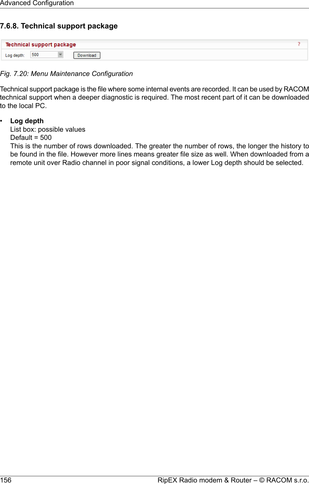
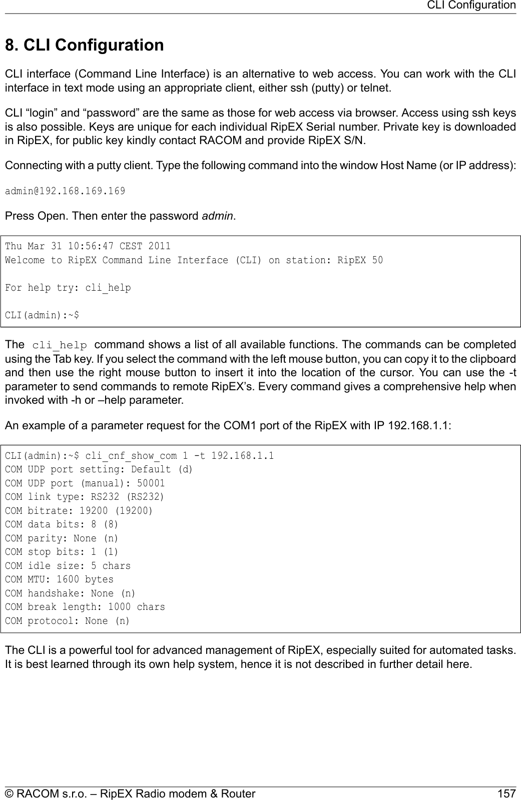
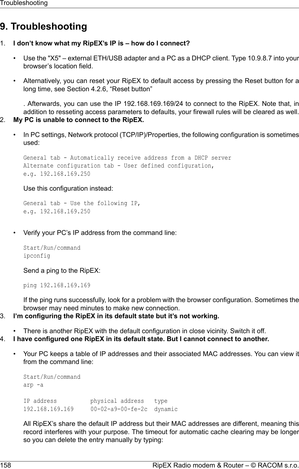
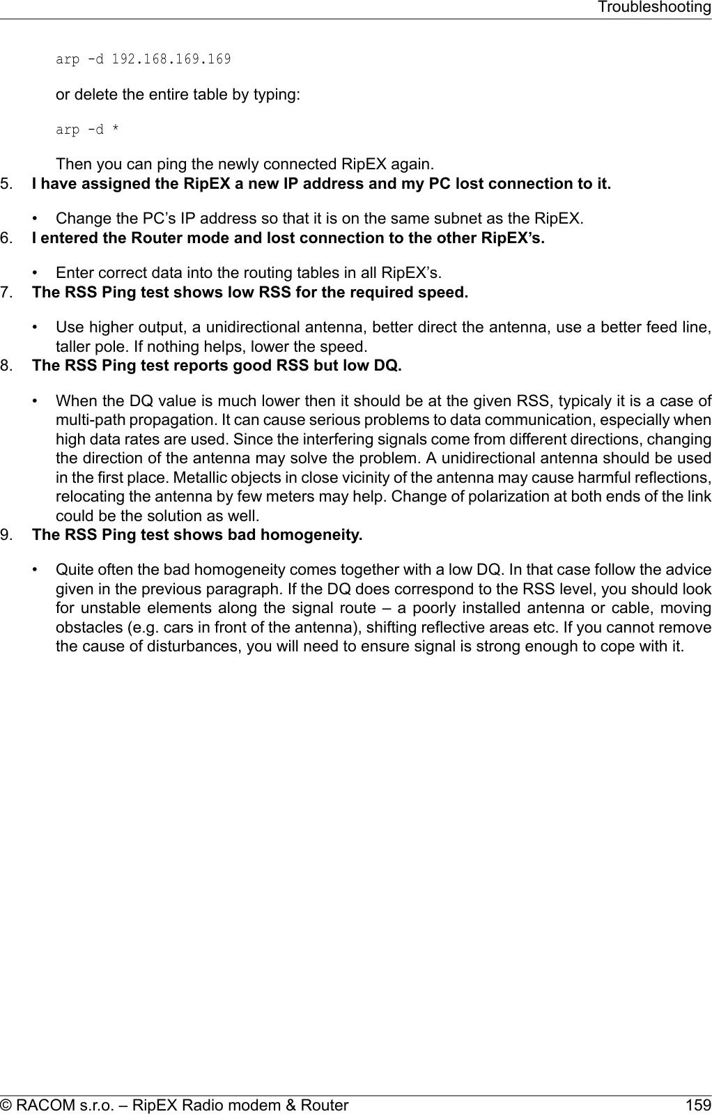
![10. Safety, environment, licensing10.1. FrequencyThe radio modem must be operated only in accordance with the valid frequency license issued by na-tional frequency authority and all radio parametres have to be set exactly as listed.ImportantUse of frequencies between 406.0 and 406.1 MHz is worldwide-allocated only for Interna-tional Satellite Search and Rescue System. These frequencies are used for distress beaconsand are incessantly monitored by the ground and satellite Cospas-Sarsat system. Otheruse of these frequencies is forbidden.10.2. Safety distanceSafety distances with respect to the US health limits of the electromagnetic field intensityare in Minimum Safety Distance tables below, calculated for different antennas andRipEX power levels. The distances were calculated according to EN 50 385 andEN 50 383 and apply to the far-field region only. Whenever the result is comparable orsmaller than the actual size of the respective antenna, the field intensity is even smallerthan the far-field based calculation and the safety limit is never exceeded. For the outputpower 0.2 W or lower the safety limit is not exceeded at any distance and any of theantennas.The minimal safe distance is typically ensured by the antenna position on a mast. When special install-ation is required, the conditions of the standard EN 50385: 2002 have to be met. The distance betweenthe persons and antenna shown in the table bellow comply with all applicable standards for humanexposure of general public to RF electromagnetic fields.Tab. 10.1: Minimum Safety Distance 160 MHz160 MHz/2 m band – 10 W RF powerDist. where the FCC limits are met forGain G[–]Gain G[dBi]Antenna descriptionAntennacodeGeneral Population/ Controlled Expos-ure [cm]General Population/ Uncontrolled Ex-posure [cm]901902.94.6single dipoleOV160.11202705.87.6stacked double dipoleOV160.21302806.38.03 element directional YagiSA160.321046017.812.55 element directional YagiSA160.5160 MHz/2 m band – 5 W RF powerDist. where the FCC limits are met forGain G[–]Gain G[dBi]Antenna descriptionAntennacodeGeneral Population/ Controlled Expos-ure [cm]General Population/ Uncontrolled Ex-posure [cm]601402.94.6single dipoleOV160.1RipEX Radio modem & Router – © RACOM s.r.o.160Safety, environment, licensing](https://usermanual.wiki/Racom/RIPEX-215/User-Guide-2641538-Page-160.png)
![160 MHz/2 m band – 5 W RF power901905.87.6stacked double dipoleOV160.2902006.38.03 element directional YagiSA160.315033017.812.55 element directional YagiSA160.5160 MHz/2 m band – 4 W RF powerDist. where the FCC limits are met forGain G[–]Gain G[dBi]Antenna descriptionAntennacodeGeneral Population/ Controlled Expos-ure [cm]General Population/ Uncontrolled Ex-posure [cm]601202.94.6single dipoleOV160.1801705.87.6stacked double dipoleOV160.2801806.38.03 element directional YagiSA160.313029017.812.55 element directional YagiSA160.5160 MHz/2 m band – 3 W RF powerDist. where the FCC limits are met forGain G[–]Gain G[dBi]Antenna descriptionAntennacodeGeneral Population/ Controlled Expos-ure [cm]General Population/ Uncontrolled Ex-posure [cm]451102.94.6single dipoleOV160.1701505.87.6stacked double dipoleOV160.2701506.38.03 element directional YagiSA160.312026017.812.55 element directional YagiSA160.5160 MHz/2 m band – 2 W RF powerDist. where the FCC limits are met forGain G[–]Gain G[dBi]Antenna descriptionAntennacodeGeneral Population/ Controlled Expos-ure [cm]General Population/ Uncontrolled Ex-posure [cm]40902.94.6single dipoleOV160.1601205.87.6stacked double dipoleOV160.2601306.38.03 element directional YagiSA160.310021017.812.55 element directional YagiSA160.5160 MHz/2 m band – 1 W RF powerDist. where the FCC limits are met forGain G[–]Gain G[dBi]Antenna descriptionAntennacodeGeneral Population/ Controlled Expos-ure [cm]General Population/ Uncontrolled Ex-posure [cm]30602.94.6single dipoleOV160.140905.87.6stacked double dipoleOV160.240906.38.03 element directional YagiSA160.3161© RACOM s.r.o. – RipEX Radio modem & RouterSafety, environment, licensing](https://usermanual.wiki/Racom/RIPEX-215/User-Guide-2641538-Page-161.png)
![160 MHz/2 m band – 1 W RF power7015017.812.55 element directional YagiSA160.5Tab. 10.2: Minimum Safety Distance 216–220 MHz216–220 MHz – 10 W RF powerDist. where the FCC limits are met forGain G[–]Gain G[dBi]Antenna descriptionAntennacodeGeneral Population/ Controlled Expos-ure [cm]General Population/ Uncontrolled Ex-posure [cm]651352.94.6single dipoleOV200.1901955.87.6stacked double dipoleOV200.2901955.87.63 element directional YagiSA200.3Tab. 10.3: Minimum Safety Distance 300–400 MHz300–400 MHz/70 cm band – 10 W RF powerDist. where the FCC limits are met forGain G[–]Gain G[dBi]Antenna descriptionAntennacodeGeneral Population/ Controlled Expos-ure [cm]General Population/ Uncontrolled Ex-posure [cm]601302.94.6single dipoleOV380.1801805.87.6stacked double dipoleOV380.2801805.87.63 element directional YagiSA380.3902007.48.75 element directional YagiSA380.514031017.812.59 element directional YagiSA380.9300–400 MHz/70 cm band – 5 W RF powerDist. where the FCC limits are met forGain G[–]Gain G[dBi]Antenna descriptionAntennacodeGeneral Population/ Controlled Expos-ure [cm]General Population/ Uncontrolled Ex-posure [cm]40902.94.6single dipoleOV380.1601305.87.6stacked double dipoleOV380.2601305.87.63 element directional YagiSA380.3701407.48.75 element directional YagiSA380.510022017.812.59 element directional YagiSA380.9300–400 MHz/70 cm band – 4 W RF powerDist. where the FCC limits are met forGain G[–]Gain G[dBi]Antenna descriptionAntennacodeGeneral Population/ Controlled Expos-ure [cm]General Population/ Uncontrolled Ex-posure [cm]35802.94.6single dipoleOV380.1501105.87.6stacked double dipoleOV380.2RipEX Radio modem & Router – © RACOM s.r.o.162Safety, environment, licensing](https://usermanual.wiki/Racom/RIPEX-215/User-Guide-2641538-Page-162.png)
![300–400 MHz/70 cm band – 4 W RF power501105.87.63 element directional YagiSA380.3601307.48.75 element directional YagiSA380.59020017.812.59 element directional YagiSA380.9300–400 MHz/70 cm band – 3 W RF powerDist. where the FCC limits are met forGain G[–]Gain G[dBi]Antenna descriptionAntennacodeGeneral Population/ Controlled Expos-ure [cm]General Population/ Uncontrolled Ex-posure [cm]30702.94.6single dipoleOV380.1451005.87.6stacked double dipoleOV380.2451005.87.63 element directional YagiSA380.3501107.48.75 element directional YagiSA380.58017017.812.59 element directional YagiSA380.9300–400 MHz/70 cm band – 2 W RF powerDist. where the FCC limits are met forGain G[–]Gain G[dBi]Antenna descriptionAntennacodeGeneral Population/ Controlled Expos-ure [cm]General Population/ Uncontrolled Ex-posure [cm]25602.94.6single dipoleOV380.135805.87.6stacked double dipoleOV380.235805.87.63 element directional YagiSA380.340907.48.75 element directional YagiSA380.57014017.812.59 element directional YagiSA380.9300–400 MHz/70 cm band – 1 W RF powerDist. where the FCC limits are met forGain G[–]Gain G[dBi]Antenna descriptionAntennacodeGeneral Population/ Controlled Expos-ure [cm]General Population/ Uncontrolled Ex-posure [cm]20402.94.6single dipoleOV380.125605.87.6stacked double dipoleOV380.225605.87.63 element directional YagiSA380.330707.48.75 element directional YagiSA380.55010017.812.59 element directional YagiSA380.9300–400 MHz/70 cm band – 0.5 W RF powerDist. where the FCC limits are met forGain G[–]Gain G[dBi]Antenna descriptionAntennacodeGeneral Population/ Controlled Expos-ure [cm]General Population/ Uncontrolled Ex-posure [cm]163© RACOM s.r.o. – RipEX Radio modem & RouterSafety, environment, licensing](https://usermanual.wiki/Racom/RIPEX-215/User-Guide-2641538-Page-163.png)
![300–400 MHz/70 cm band – 0.5 W RF power15302.94.6single dipoleOV380.120405.87.6stacked double dipoleOV380.220405.87.63 element directional YagiSA380.320457.48.75 element directional YagiSA380.5307017.812.59 element directional YagiSA380.9Tab. 10.4: Minimum Safety Distance 928–960 MHz928–960 MHz – 8 W RF powerDist. where the FCC limits are met forGain G[–]Gain G[dBi]Antenna descriptionAntennacodeGeneral Population/ Controlled Expos-ure [cm]General Population/ Uncontrolled Ex-posure [cm]30.869.02.924.65single dipoleOV900.148.9109.37.338.655 element directional YagiSA900.592.1205.926.014.1512 element directional YagiSA900.1210.3. High temperatureIf the RipEX is operated in an environment where the ambient temperature exceeds55 °C, the RipEX must be installed within a restricted access location to prevent humancontact with the enclosure heatsink.10.4. RoHS and WEEE complianceThe RipEX is fully compliant with the European Commission‟s RoHS (Restriction of Certain HazardousSubstances in Electrical and Electronic Equipment) and WEEE (Waste Electrical and ElectronicEquipment) environmental directives.Restriction of hazardous substances (RoHS)The RoHS Directive prohibits the sale in the European Union of electronic equipment containing thesehazardous substances: lead, cadmium, mercury, hexavalent chromium, polybrominated biphenyls(PBBs), and polybrominated diphenyl ethers (PBDEs).End-of-life recycling programme (WEEE)The WEEE Directive concerns the recovery, reuse, and recycling of electronic andelectrical equipment. Under the Directive, used equipment must be marked, collectedseparately, and disposed of properly. Racom has instigated a programme to managethe reuse, recycling, and recovery of waste in an environmentally safe manner usingprocesses that comply with the WEEE Directive (EU Waste Electrical and ElectronicEquipment 2002/96/EC).Battery Disposal—This product may contain a battery. Batteries must be disposed of properly, andmay not be disposed of as unsorted municipal waste in the European Union. See the product docu-RipEX Radio modem & Router – © RACOM s.r.o.164Safety, environment, licensing](https://usermanual.wiki/Racom/RIPEX-215/User-Guide-2641538-Page-164.png)