ROTRONIC AFP1 Air Flow Probe User Manual
ROTRONIC AG Air Flow Probe Users Manual
UserManual.wiki
>
ROTRONIC
>
AFP1 User Manual
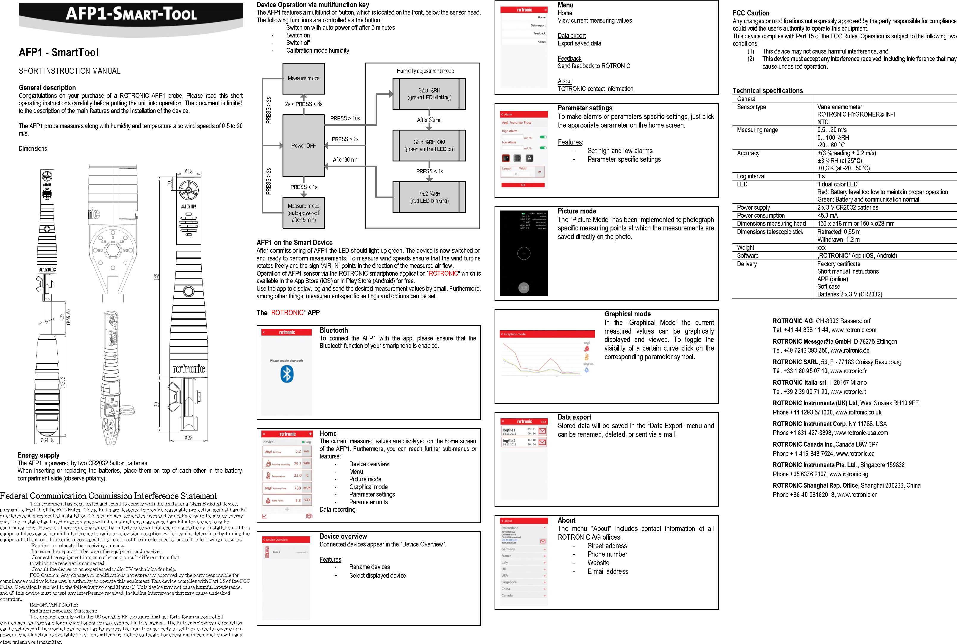
Users Manual
Navigation menu
Upload a User Manual
Namespaces
Wiki Guide
HTML
PDF
Info
Views
User Manual
Discussion / Help
Navigation