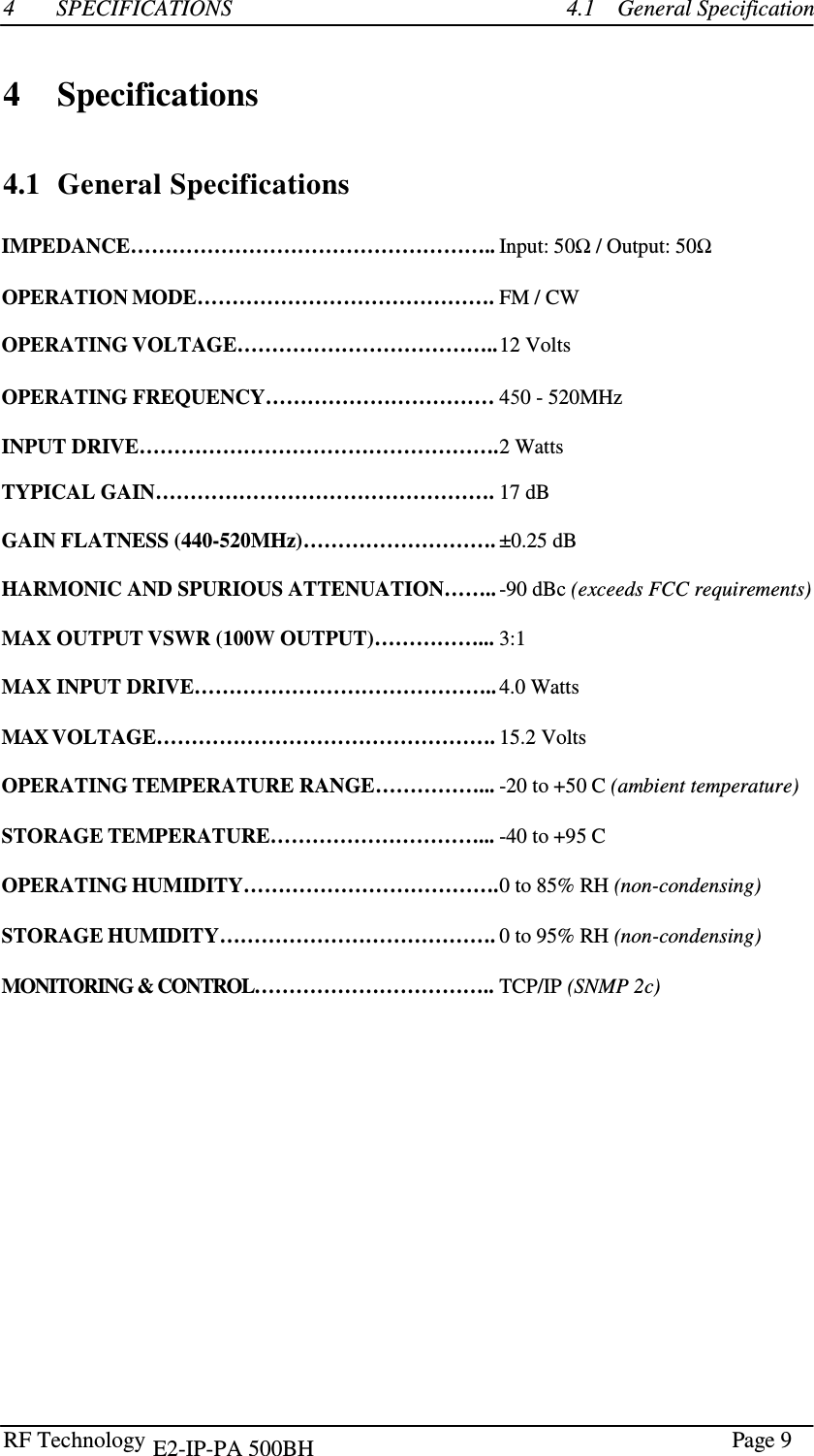
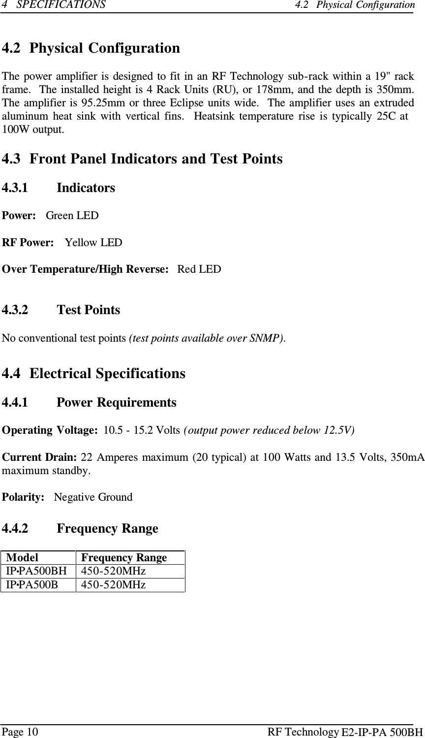
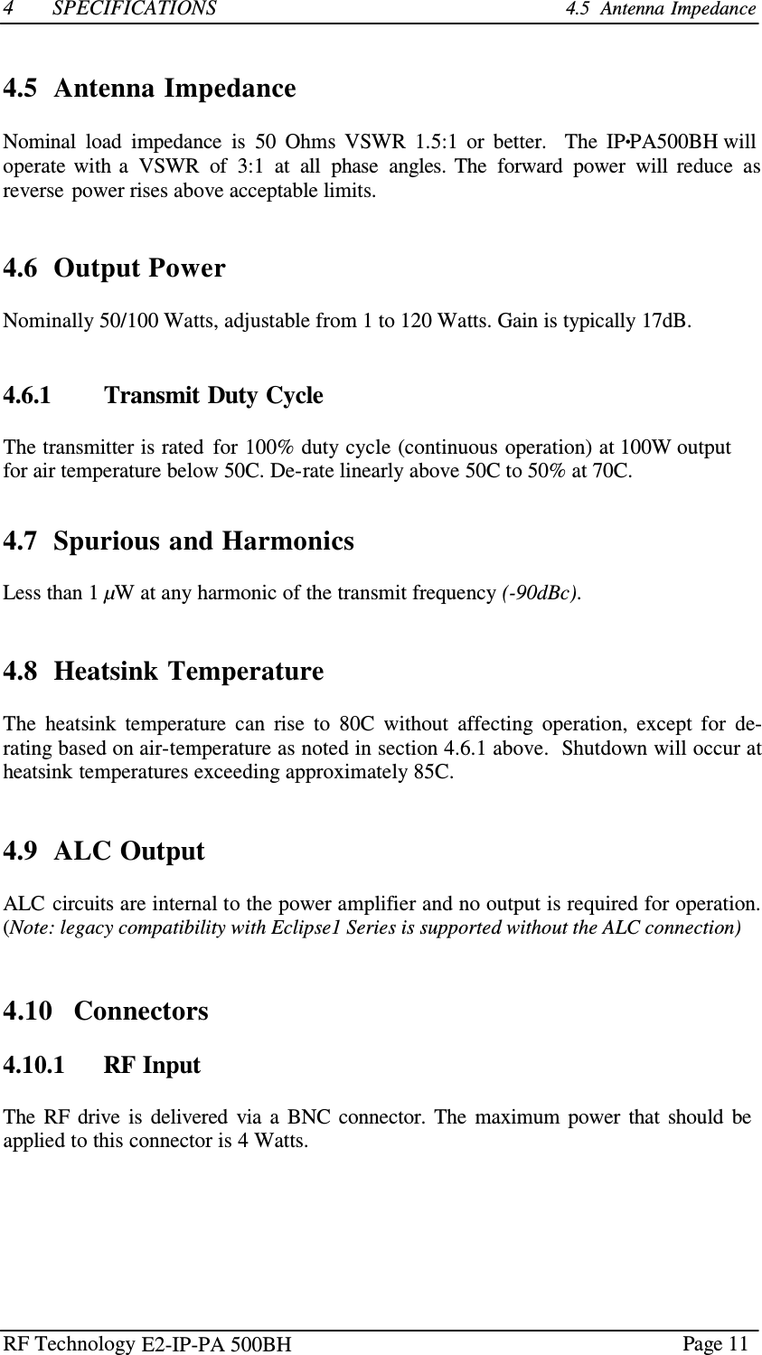
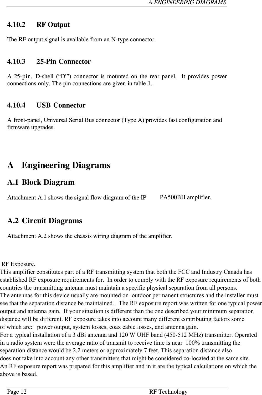
RF Technology E2-IP-PA500BH UHF BASE STATION AMPLIFIER User Manual manual IP PA500BH rev0

RF Technology Pty Ltd UHF BASE STATION AMPLIFIER manual IP PA500BH rev0

User Manual

             Eclipse2 September 2012 sales@rftechnology.com.au            E2-IP-·PA500BH Amplifier  Operation and Maintenance Manual                             This manual is produced by RF Technology Pty. Ltd. 46/7 Sefton Road, Thornleigh, 2120, Australia Copyright © 2012 RF Technology Pty. Ltd.
RF Technology      Page 2   CONTENTS  CONTENTS    Contents     1  Operating Instructions 1.1  Installation  4 4  1.1.1  Sub-rack Wiring Guidelines  4  1.2 Front Panel Indicators  5  1.3 Internal Adjustments  5  1.4 Amplifier I/O Connections  5  1.4.1  RF Input  6  1.4.2  RF Output  6  1.4.3  25 Pin Connector  6  1.4.4 RJ45 Ethernet Connector 6   2  Circuit Description 2.1  Amplifiers  6 6  2.2  Power Splitter / Combiners  7  2.3 Directional Coupler 7  2.4 Low Pass Filter 7  2.5 Power Control Circuits 7  2.6 RF Output Indicator 8  2.7 Over Temperature Protection  8   3  Field Alignment Procedures  8  3.1  Output Power Level  8  3.2 Tuning Procedure  8   4  Specifications 4.1  General Specifications  9 9  4.2  Physical Configuration 10 4.3 Front Panel Indicators and Test Points 10 4.3.1  Indicators 10 4.3.2  Test Points 4.4  Electrical Specifications 1010 4.4.1  Power Requirements 10 4.4.2  Frequency Range 10 4.5 Antenna Impedance  11 4.6  Output Power 4.6.1  Transmit Duty Cycle 1111 4.7  Spurious and Harmonics  11 4.8 Heatsink Temperature 11 4.9 ALC Output  11 4.10  Connectors 11 4.10.1  RF Input  11 4.10.2  RF Output 12 4.10.3  25-Pin Connector 12 4.10.4  USB Connector 12 E2-IP-PA 500BH
RF Technology    E2-IP-PA 500BH Page 3  CONTENTS  CONTENTS     A       Engineering Diagrams                                                         Attachment A.1             Functional Diagrams                                           1 A.2             Wiring Diagrams                                                  2
Page 4 RF Technology    1  OPERATING INSTRUCTIONS          1.1   Installation    WARNING    Changes or modifications not expressly approved by RF Technology could void your authority to operate this equipment.   Specifications may vary from  those given  in  this  document    in  accordance  with requirements  of  local  authorities.   RF  Technology equipment  is  subject  to  continual  improvement  and RF  Technology   reserves  the  right  to  change performance and specification without further notice.    1    Operating Instructions  The  IP•PA500BH  is  part  of  the  Eclipse2  range  of  modular  base  station  equipment.   It is  a broadband Solid State Internet Protocol RF Power Amplifier (SS•IP•PA) capable of delivering over 100 Watts in the UHF frequency range.   It is designed to complement the Eclipse2 Software Defined Radio (SDR), and mounts in a standard Eclipse sub-rack.  1.1  Installation  There  are  no  front  panel  controls.    In  normal  circumstances  no  alignment  or  setup  is required.    If  mounted  in  a  sub-rack  that  has  not  previously  been  wired  for  a  power amplifier, the rack connector  must be wired according to the  guidelines in section 1.1.1 below.    1.1.1        Sub-rack Wiring Guidelines  When  installing  an  Eclipse  Power  Amplifier  in  an  Eclipse  sub-rack,  observe  the following guidelines for sub-rack installation:  The   sub-rack   power   supply   must   be   capable   of   delivering   the   full   current requirements  for  all  modules  fitted  in  the  sub-rack,  typically  20  Amperes  for  a 100W basestation/amplifier.  Owing  to  the  current  drain,  power  supply  lines  should  be  cabled  to  the  power amplifier  separately  and  using  heavy  gauge  wire  to  minimise  voltage  drop  and interference via the power supply of other modules in the rack. E2-IP-PA 500BH
RF Technology    • Page 5  1  OPERATING INSTRUCTIONS  1.3   Internal Adjustments  1.2  Front Panel Indicators   PWR LED  The  power  (PWR)  LED  shows  that  the  dc  supply  is  connected  to  the amplifier.  RFO LED  The  RF  output  (RFO)  LED  indicates  that  the  amplifier  is being  driven and there is forward RF power present at the output.   ALARM LED  The  alarm  (ALARM)  LED  illuminates if  the  internal  temperature  rises   above  safe  limits  or  high  reverse  power  is  present,  output  power  is automatically reduced in order to protect the amplifier.      1.3 Internal Adjustments  All internal adjustments are factory set and should not need to be changed under normal conditions. A  possible exception  to  this  is  the  RF  output  power  level  which  may  need to be changed to comply with local licensing requirements.         WARNING  Ensure  that  the  power  setting  complies  with  the requirements  of  your  licensing  authority.  Failure  to  do so  may  result  in  penalties  being  imposed  by  the licensing authority.       Output Power The  output  power  is  set  by  RV1.  This  is  nominally  set  to  100  Watts (+50dBm),  but  may  be  set  to  any  value  between  1  and  120  Watts depending  upon  local  regulations  in  the  destination  country,  and  the model of power amplifier.      1.4  Amplifier I/O Connections  The IP•PA500BH has four connectors on the rear panel.   E2-IP-PA 500BH
Page 6 RF Technology    2   CIRCUIT DESCRIPTION  1.4.1   RF Input  The  RF  drive  is  delivered  via  the  BNC  connector. Input drive level is 2 Watts,  the absolute  maximum  power  that should be applied to this connector is 4 Watts.   1.4.2   RF Output  The RF output signal is available from an N-type connector. The input/output impedance is 50 ohms.  1.4.3       25 Pin Connector  The  25-pin  “D”  connector  provides  connection  to  ground  and  dc  power.  The  pin connections  are  given  in  table  1.       1.4.4  RJ45 Ethernet Connector  The  RJ45  connector  is  used  to  monitor  and  configure  a  range  of  parameters  remotely using the Internet Protocol over Ethernet.     Pins Function 1, 2, 3, 4, 14, 15, 16, 17 Positive supply 9, 10, 11, 12, 13, 22, 23, 24, 25 Ground (negative supply)  Table 1:   Pin connections for the 25 pin “D” connector on the rear panel      2     Circuit Description  The following descriptions should be read as an aid to understanding the diagrams shown in figures A.1 and A.2.    2.1   Amplifiers  The RF power amplification is provided by two RF MOSFET modules, U15 and U16. Module  technology  is  used  in  this  amplifier  to  guarantee  superior  reliability,  this technology  has  been  field  proven  in  tens  of  millions  of  radios  over  the  past  25  years.  Each  module  is  rated  at  60  watts  output.    The  input  and  output  impedances  are internally matched  to 50 Ohms.   The 50W models have only has module fitted.   E2-IP-PA 500BH
RF Technology    Page 7  2  CIRCUIT DESCRIPTION 2.2   Power Splitter / Combiners    No trimmer  capacitors or  inductors  are  used  for  input/output  matching,  the  broadband design  means no re-adjustment is  required  even if the  frequency is  changed from  one end  of  the  band  to the other.  The  dc  supply  is  fed  to  the  amplifiers  through  resistors  R166  and  R167.   This  allows the current of each amplifier to be monitored.    2.2  Power Splitter / Combiners  In  the  100W  models,  a   zero-degree  broadband  splitter  and  zero-degree  hybrid power combiner is used to parallel the two amplifier stages. This configuration provides a very wide bandwidth and better balance compared with lower cost 90-degree hybrids.    2.3  Directional  Coupler  The  forward  and  reverse  power  components  are  measured  through  an  asymmetric stripline  directional  coupler.  The  output  of  the  coupled  lines  measured  by  two temperature and frequency  compensated detectors.    2.4  Low Pass Filter  A low pass filter consisting reduces the harmonic components to less than -90dBc. The filter uses shielded lumped elements to obtain the required harmonic attenuation.    2.5  Power Control Circuits  The  forward  and  reverse  voltages  from  the  directional  coupler  are  amplified  and combined in the ALC error amplifier.  The Error amplifier compares the detected voltages with the dc reference voltages from output power trimpot RV1 and reverse power trimpot RV2. The amplified difference is used to control the output power of the RF MOSFET Modules. E2-IP-PA 500BH
Page 8  RF Technology    2   CIRCUIT DESCRIPTION 3.   Field alignment procedure    Equipment Type Key Specifications Power Supply  13.8Vdc,  25A RF Source 2 Watt (eg. Eclipse2 Basestation) RF Load / Attenuator 50Ω, 100W, SWR<1.2:1 RF Power Meter eg. calibrated detector and voltmeter Short Circuit  N-type, 0Ω, 100W Short   Table 2:  Standard test equipment for the IP•PA500BH Power Amplifier    2.6  RF Output Indicator  The forward power voltage is compared with a pre-set dc reference voltage by  U23.   The output  of  U23  is  used  to  turn  on  the  RFO  LED. The reference voltage is set to turn on the led when output power is between 1-120 Watts.     2.7  Over Temperature Protection   Thermistors  RT1  and  RT2  are  mounted  to  the  case  of  RF module  U15 and U16.   If either module  case temperature  rises  above  85  Celsius  the  resistance  of  RT1 or RT2 increases  and  Q25 or Q26  is  turned ON.  This causes the TEMP LED to come on and also reduces the dc reference voltage to the output  power  error  amplifier  U22.  The  output  power  will  then  be  reduced  by  the amplifiers ALC circuits and the modules are kept within safe operating limits.   3    Field Alignment Procedures    3.1  Output Power Level and Reverse Power Limit  1.   Set the unit up on a bench with the standard test equipment listed in table 2.  2.   Set *RV1 fully counter-clockwise and *RV2 fully clockwise.  3.   Set the Eclipse2 basestation to the desired operating frequency.  4.   Adjust RV1 for the desired output power.  5.   Disconnect power and swap load with the N-type short.  6.   Set *RV2 both fully counter-clockwise.  7.   Apply Power and adjust *RV2 for maximum reverse power (Typically 25Watts).   3.2  Tuning Procedure  No further Tuning or Adjustment is required.   *(Note: RV1 and RV2 may be replaced with fixed value resistors R279, R153, R154, R155 and R156) E2-IP-PA 500BH
RF Technology      Page 9  4  SPECIFICATIONS  4.1    General Specification    4    Specifications    4.1  General Specifications  IMPEDANCE…………………………………………….. Input: 50Ω / Output: 50Ω  OPERATION MODE……………………………………. FM / CW  OPERATING VOLTAGE……………………………….. 12 Volts  OPERATING FREQUENCY…………………………… 450 - 520MHz   INPUT DRIVE……………………………………………. 2 Watts  TYPICAL GAIN…………………………………………. 17 dB  GAIN FLATNESS (440-520MHz)………………………. ±0.25 dB HARMONIC AND SPURIOUS ATTENUATION…….. -90 dBc (exceeds FCC requirements)  MAX OUTPUT VSWR (100W OUTPUT)……………... 3:1  MAX INPUT DRIVE…………………………………….. 4.0 Watts  MAX VOLTAGE…………………………………………. 15.2 Volts   OPERATING TEMPERATURE RANGE……………... -20 to +50 C (ambient temperature)  STORAGE TEMPERATURE…………………………... -40 to +95 C  OPERATING HUMIDITY………………………………. 0 to 85% RH (non-condensing)  STORAGE HUMIDITY…………………………………. 0 to 95% RH (non-condensing)  MONITORING & CONTROL…………………………….. TCP/IP (SNMP 2c)   E2-IP-PA 500BH
Page 10 RF Technology    4   SPECIFICATIONS 4.2   Physical Configuration    4.2  Physical Configuration  The power amplifier is designed to fit in an RF Technology sub-rack within a 19" rack frame.   The installed height is 4 Rack Units (RU), or 178mm, and the depth is 350mm. The amplifier is 95.25mm or  three Eclipse units wide.   The amplifier  uses an extruded aluminum  heat  sink  with  vertical  fins.   Heatsink  temperature  rise  is  typically  25C at 100W output.  4.3  Front Panel Indicators and Test Points  4.3.1        Indicators  Power:   Green LED  RF Power:    Yellow LED  Over Temperature/High Reverse:   Red LED    4.3.2        Test Points  No conventional test points (test points available over SNMP).   4.4  Electrical Specifications  4.4.1        Power Requirements  Operating Voltage:  10.5 - 15.2 Volts (output power reduced below 12.5V)  Current Drain: 22 Amperes maximum (20 typical) at 100 Watts and 13.5 Volts, 350mA maximum standby.  Polarity:   Negative Ground   4.4.2        Frequency Range  Model Frequency Range IP•PA500BH 450-520MHz IP•PA500B 450-520MHz E2-IP-PA 500BH
RF Technology    Page 11  4  SPECIFICATIONS 4.5  Antenna Impedance    4.5  Antenna Impedance  Nominal  load  impedance  is  50  Ohms  VSWR  1.5:1  or  better.    The  IP•PA500BH will operate  with a  VSWR  of  3:1  at  all  phase  angles.  The  forward  power  will  reduce  as reverse  power rises above acceptable limits.    4.6  Output Power  Nominally 50/100 Watts, adjustable from 1 to 120 Watts. Gain is typically 17dB.    4.6.1        Transmit Duty Cycle  The transmitter is rated  for 100% duty cycle (continuous operation) at 100W output for air temperature below 50C. De-rate linearly above 50C to 50% at 70C.   4.7  Spurious and Harmonics  Less than 1 µW at any harmonic of the transmit frequency (-90dBc).    4.8  Heatsink Temperature  The  heatsink  temperature  can  rise  to  80C  without  affecting  operation,  except  for  de- rating based on air-temperature as noted in section 4.6.1 above.  Shutdown will occur at heatsink temperatures exceeding approximately 85C.    4.9  ALC Output  ALC circuits are internal to the power amplifier and no output is required for operation. (Note: legacy compatibility with Eclipse1 Series is supported without the ALC connection)    4.10   Connectors  4.10.1      RF Input  The  RF  drive  is  delivered  via  a  BNC  connector.  The  maximum  power  that  should  be applied to this connector is 4 Watts. E2-IP-PA 500BH
Page 12  RF Technology     A ENGINEERING DIAGRAMS    4.10.2   RF Output  The RF output signal is available from an N-type connector.    4.10.3   25-Pin Connector  A  25-pin,  D-shell  (“D”')  connector  is  mounted  on  the  rear  panel.   It  provides  power connections only. The pin connections are given in table 1.    4.10.4   USB Connector  A front-panel, Universal Serial Bus connector (Type A) provides fast configuration and firmware upgrades.       A  Engineering Diagrams  A.1  Block Diagram  Attachment A.1 shows the signal flow diagram of the IP•PA500BH amplifier.     A.2  Circuit Diagrams  Attachment A.2 shows the chassis wiring diagram of the amplifier.       RF Exposure.  This amplifier constitutes part of a RF transmitting system that both the FCC and Industry Canada has established RF exposure requirements for.  In order to comply with the RF exposure requirements of both countries the transmitting antenna must maintain a specific physical separation from all persons. The antennas for this device usually are mounted on  outdoor permanent structures and the installer must see that the separation distance be maintained.   The RF exposure report was written for one typical power output and antenna gain.  If your situation is different than the one described your minimum separationdistance will be different. RF exposure takes into account many different contributing factors some of which are:   power output, system losses, coax cable losses, and antenna gain.  For a typical installation of a 3 dBi antenna and 120 W UHF band (450-512 MHz) transmitter. Operated  in a radio system were the average ratio of transmit to receive time is near  100% transmitting the separation distance would be 2.2 meters or approximately 7 feet. This separation distance also does not take into account any other transmitters that might be considered co-located at the same site. An RF exposure report was prepared for this amplifier and in it are the typical calculations on which the above is based.          E2-IP-PA 500BH

Navigation menu