RF Controls ITCSA104 RF ID Signal Acquisition & Source Location unit ITCS104 User Manual 11001 011 REV0v92

RF Controls, LLC RF ID Signal Acquisition & Source Location unit ITCS104 11001 011 REV0v92

Contents

User Manual 3

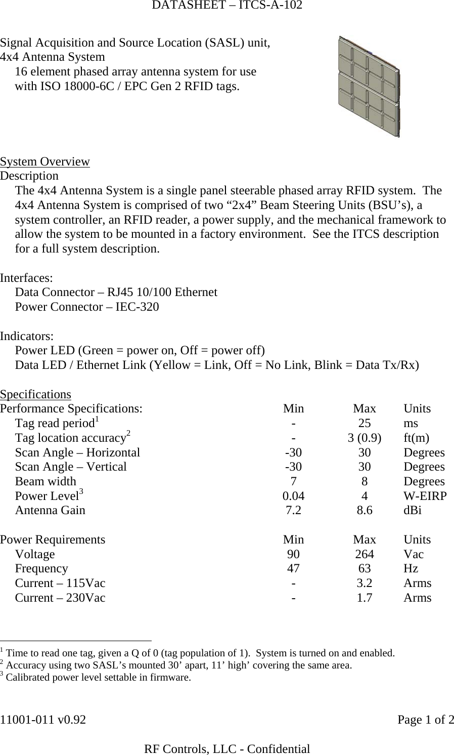
DATASHEET – ITCS-A-102    11001-011 v0.92    Page 1 of 2   RF Controls, LLC - Confidential Signal Acquisition and Source Location (SASL) unit, 4x4 Antenna System   16 element phased array antenna system for use with ISO 18000-6C / EPC Gen 2 RFID tags.   System Overview Description   The 4x4 Antenna System is a single panel steerable phased array RFID system.  The 4x4 Antenna System is comprised of two “2x4” Beam Steering Units (BSU’s), a system controller, an RFID reader, a power supply, and the mechanical framework to allow the system to be mounted in a factory environment.  See the ITCS description for a full system description.  Interfaces:   Data Connector – RJ45 10/100 Ethernet   Power Connector – IEC-320    Indicators:   Power LED (Green = power on, Off = power off)   Data LED / Ethernet Link (Yellow = Link, Off = No Link, Blink = Data Tx/Rx)  Specifications Performance Specifications:  Min  Max  Units   Tag read period1 - 25 ms   Tag location accuracy2 - 3 (0.9) ft(m)   Scan Angle – Horizontal  -30  30  Degrees   Scan Angle – Vertical  -30  30  Degrees  Beam width  7  8  Degrees  Power Level3 0.04 4 W-EIRP  Antenna Gain  7.2  8.6  dBi         Power Requirements  Min  Max  Units  Voltage  90  264  Vac  Frequency  47  63  Hz   Current – 115Vac  -  3.2  Arms   Current – 230Vac  -  1.7  Arms                                                          1 Time to read one tag, given a Q of 0 (tag population of 1).  System is turned on and enabled. 2 Accuracy using two SASL’s mounted 30’ apart, 11’ high’ covering the same area. 3 Calibrated power level settable in firmware.
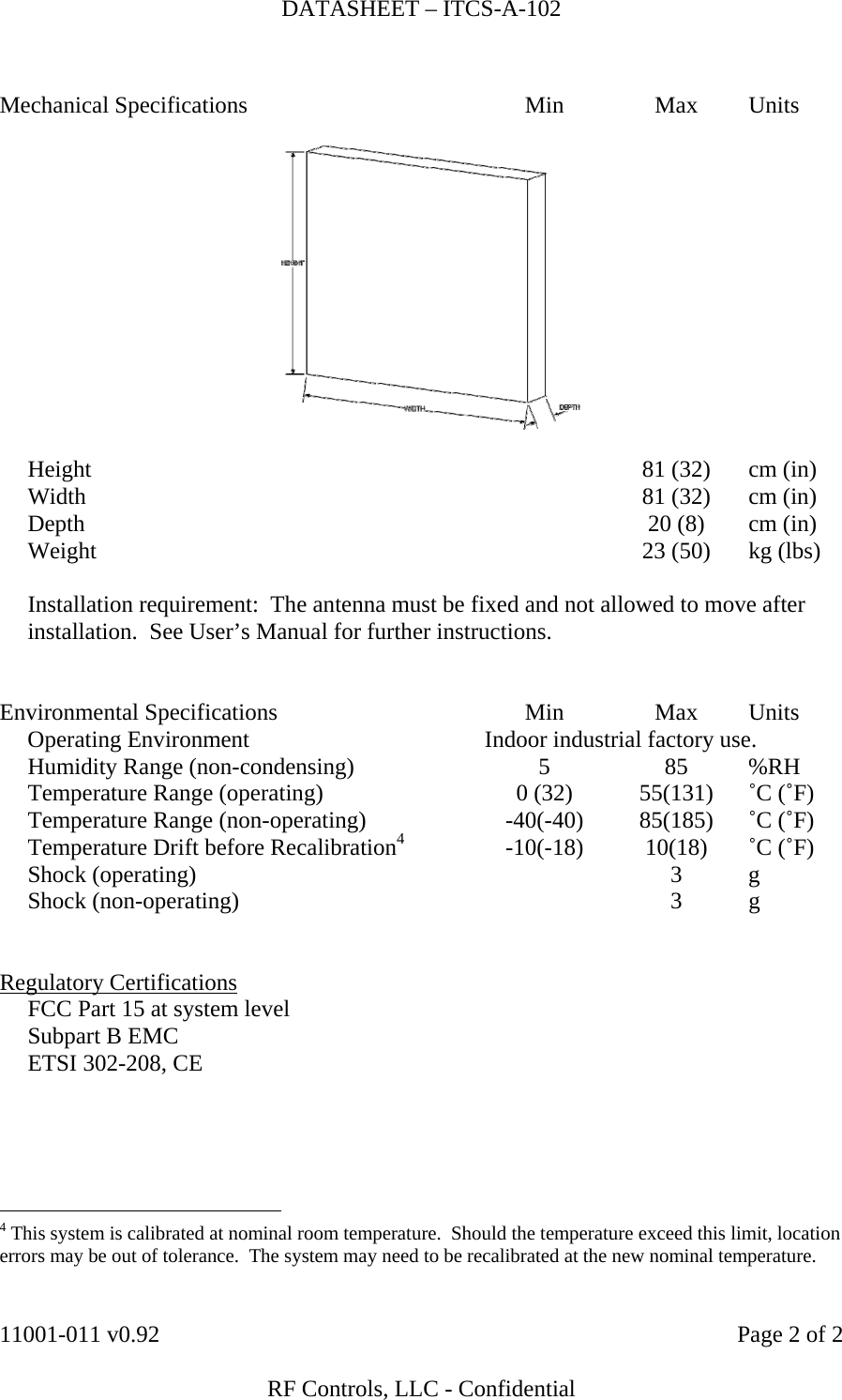
DATASHEET – ITCS-A-102    11001-011 v0.92    Page 2 of 2   RF Controls, LLC - Confidential  Mechanical Specifications  Min  Max  Units       Height    81 (32)  cm (in)   Width    81 (32)  cm (in)   Depth    20 (8)  cm (in)   Weight    23 (50)  kg (lbs)           Installation requirement:  The antenna must be fixed and not allowed to move after installation.  See User’s Manual for further instructions.   Environmental Specifications  Min  Max  Units  Operating Environment  Indoor industrial factory use.   Humidity Range (non-condensing)  5  85  %RH   Temperature Range (operating)  0 (32)  55(131)  ˚C (˚F)   Temperature Range (non-operating)  -40(-40)  85(185)  ˚C (˚F)   Temperature Drift before Recalibration4 -10(-18) 10(18) ˚C (˚F)  Shock (operating)    3  g  Shock (non-operating)    3  g          Regulatory Certifications   FCC Part 15 at system level   Subpart B EMC   ETSI 302-208, CE                                                   4 This system is calibrated at nominal room temperature.  Should the temperature exceed this limit, location errors may be out of tolerance.  The system may need to be recalibrated at the new nominal temperature.

Navigation menu