RF Controls ITCSA100 RF ID Signal Acquisition & Source Location Unit User Manual SASL Installation Guide 0v93
RF Controls, LLC RF ID Signal Acquisition & Source Location Unit SASL Installation Guide 0v93
Contents
- 1. User Manual 1 of 3
- 2. User Manual 2 of 3
- 3. User Manual 3 of 3
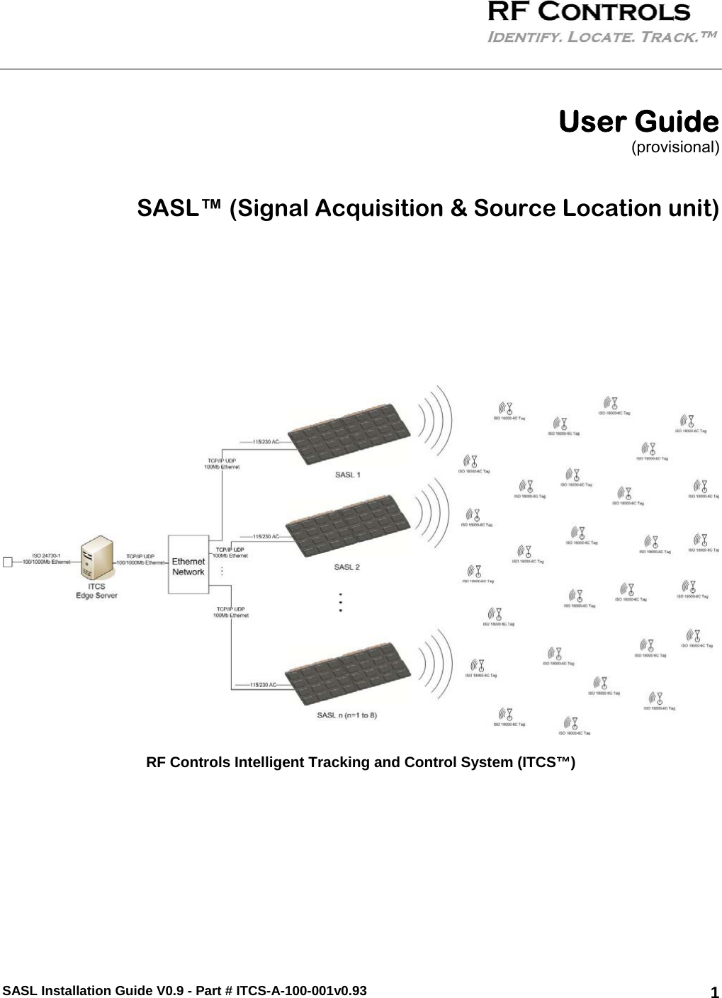
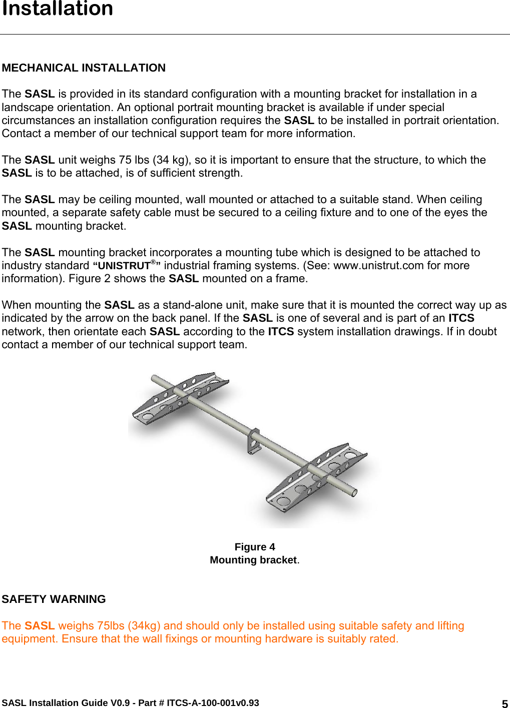
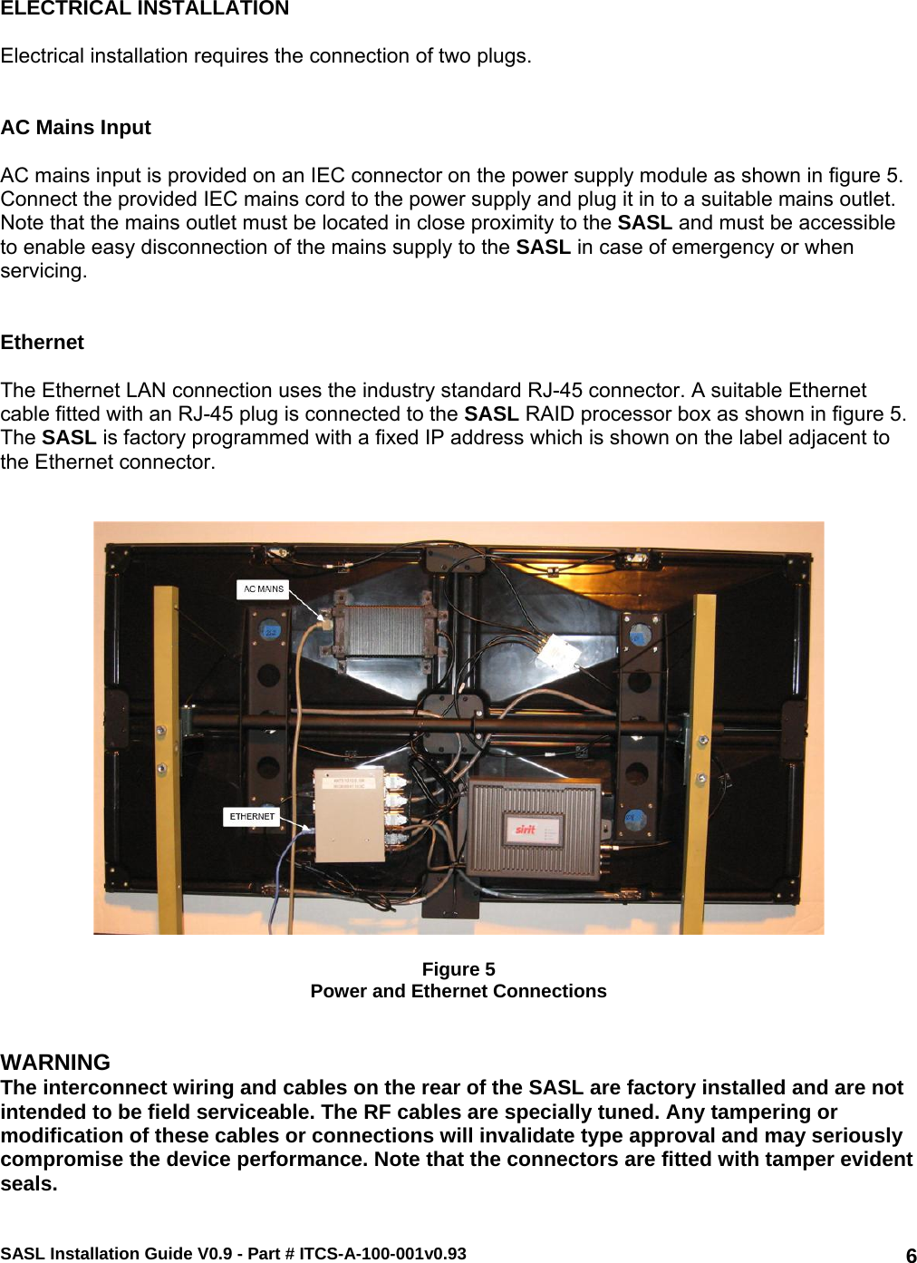
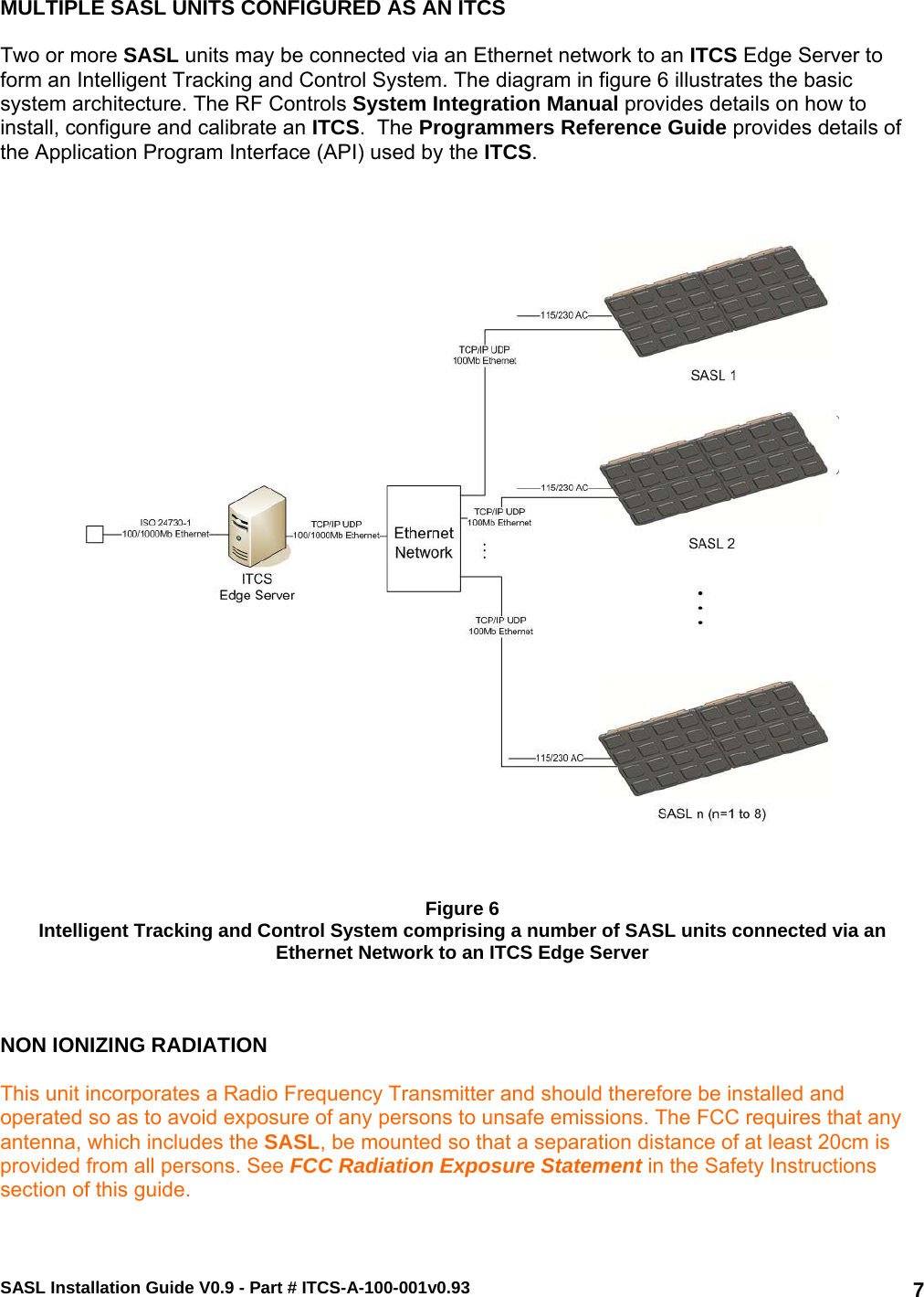
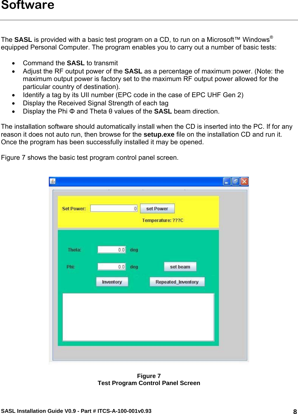
User Manual 1 of 3