RF Concepts PA06 User Manual Preliminary

RF Concepts LLC Preliminary

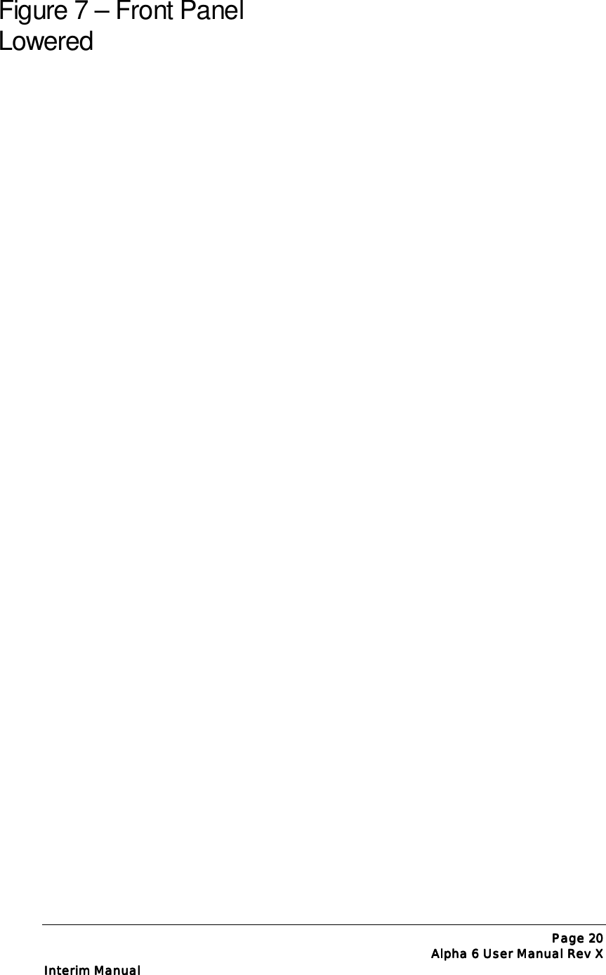
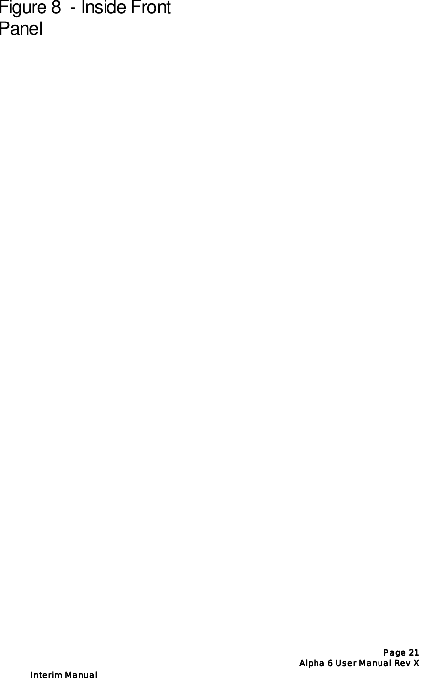
Preliminary User Manual

INTERIM MANUAL Page iiiiAlpha 6 User Manual Rev XAlpha 6 User Manual Rev XAlpha 6 User Manual Rev XAlpha 6 User Manual Rev XAAAALPHA LPHA LPHA LPHA 6666OOOOPERATING PERATING PERATING PERATING MMMMANUALANUALANUALANUALPRELIMINARY DRAFTPRELIMINARY DRAFTPRELIMINARY DRAFTPRELIMINARY DRAFTALPHA/POWERby CrossLink, Inc. RFPower for Communications and Industry6185 Arapahoe Road,Boulder, Colorado 80303-1401(303) 473-9232 * FAX (303) 473-9660
ALPHA POWER PRODUCTSALPHA 6Operating ManualDISCLAIMERInformation in this document is subject to changewithout notice.  Information provided by CrossLinkInc.® is believed to be correct and reliable.  However,no responsibility is assumed by CrossLink Inc., unlessotherwise expressly taken.  Companies, names, anddata used as examples are fictitious, unless otherwisenoted.No part of this document may be reproduced ortransmitted in any form or by any means, graphic,electronic, or mechanical, for any purpose without theexpress permission of CrossLink, Inc.  CrossLink, Inc.may have patents or pending patents, trademarks,copyrights, or other property rights covering thesubject matter in this document.  The furnishings ofthis document does not give you license to thesepatents, trademarks, copyrights, or other intellectualproperty, except as expressly written in any licenseagreement form CrossLink Inc.6185 Arapahoe Road • Boulder, CO 80303Phone 303.473.9232 • Fax 303.473.9660Read this entire manual and all other publicationspertaining to the work to be performed before youinstall, operate, or maintain this equipment.  Practiceall product safety instructions and precautions.CrossLink, Inc. provides information on its productsand associated hazards, but it assumes noresponsibility for the after-sale operation of theequipment or the safety practices of the Owner orUser.  See Warranty and Notices Appendix.©Copyright 2001 by CrossLink Inc.All rights reserved.
Page Page Page Page 2222Revision 1.0Revision 1.0Revision 1.0Revision 1.0Table of ContentsOWNER ASSISTANCE.................................................................................................................................4EQUIPMENT SHIPPED.................................................................................................................................4SAFETY:  INSTALLATION AND OPERATION ...............................................................................................5BEFORE INSTALLING YOUR ALPHA 6........................................................................................................ 6AC POWER SOURCE..................................................................................................................................7ANTENNA..................................................................................................................................................7COAX AND CONNECTORS..........................................................................................................................8AIR FLOW..................................................................................................................................................8RF SAF ETY................................................................................................................................................8TRANSFORMER INSTALLATION (SEE FIGURES 2-4) ................................................................................... 9INSPECTION OF TUBE & CHIMN EY ............................................................................................................9AC PRIMARY CONNECTIONS & AMPLIFIER GRO UNDING .......................................................................10POWER CORD CONNECTIONS — WARNING!.....................................................................................10RF GROUNDING ......................................................................................................................................11COAXIAL CABLE TYPES & CONNECTORS ............................................................................................... 13T/R CONTROL CABLE .............................................................................................................................13FIGURE 5:  ALPHA 6 REAR PAN EL ........................................................................................................ 144.1 Control Functions.........................................................................................................................154.2 Tune-up .........................................................................................................................................15Grid Current .......................................................................................................................................16ALC .....................................................................................................................................................16Tune-up Procedure .............................................................................................................................164.3  Reflected Power Protection ...................................................................................................174.4  Automatic Level Control (ALC) .............................................................................................18FIGURE 6 – INSIDE TOP VIEW ................................................................................................................. 19FIGURE 7 – FRONT PAN EL  LOWERED...................................................................................................... 20FIGURE 8  - INSIDE FRONT PANEL...........................................................................................................21OPERATING AND MAINTENANCE NOTES...................................................................................22TUBES.................................................................................................................................................22INTERLOCKS .....................................................................................................................................22FUSES.................................................................................................................................................23PLATE OVERCURRENT RELAY .......................................................................................................23FIGURE 9 - REAR PANEL CONNECTIONS .................................................................................................25TROUBLESHOOTING HINTS ............................................................................................................26DESIGN AND CIRCUIT OVERVIEW................................................................................................28RF Amplifier Section (See Figure 6, 13).............................................................................................28Power Supplies (Figures 6, 9, 12) ......................................................................................................28SAFETY.................................................................................................................................................29ALPHA PRODUCTS WARRANTY.....................................................................................................30
INTERIM MANUAL Alpha 6 User Manual Rev XAlpha 6 User Manual Rev XAlpha 6 User Manual Rev XAlpha 6 User Manual Rev XIntroductionIMPORTANTCritical precaution during installation of your Alpha 6:While the cover is removed to install the power transformer, make sure that the tubeis properly installed as described below.  Failure to do this may cause severedamage or destruction of the tube. Such damage is not covered under warranty.General Description of the ALPHA 6 AmplifierThe ALPHA 6 is a self-contained 6m VHF Linear power amplifier capable of continuousoperation at 1500 watts peak power output on SSB, keyed CW, SSTV, RTTY, digitalmodes or FM, with no time limit.  If periods of “continuous-key-down” carrier operationwill exceed 5 minutes, or if the amplifier is to be operated from 50 Hz mains, the optionalauxiliary cooling fan available from CrossLink must be installed to avoid possible damagenot covered by the warranty.All shipped, units delivered within the USA and its territories are manually tunable to coverthe entire 6m amateur band from 50-54 MHz.Specifications, ALPHA 6Frequency Coverage:  Amateur band 50-54 MHz.Power Output:  1500 watts peak all modes, including SSB, CW and continuous ormodulated carrier.  Carrier operation (e.g., A0, RTTY or FM) for more than 5 minutes at ornear maximum rated power requires use of the auxiliary cooling fan accessory.Drive Power:  50 to 60 watts nominal for rated output.Power Gain:  Nominally 14 dB, a power increase of 25 times.Input Impedance:  50 ohms nominal, unbalanced; VSWR <2:1.This manual provides allinformation necessary to install and operate the ALPHA 6.  Schematic diagrams areavailable on request, at no charge to owners.Section1
INTERIM MANUAL Page 4444   Alpha 6 User Manual Rev X   Alpha 6 User Manual Rev X   Alpha 6 User Manual Rev X   Alpha 6 User Manual Rev XOutput Impedance:   50 ohms unbalanced.Maximum Load VSWR:   2:1 at full rated power output.VSWR Trip:   Automatic standby when reflected power >250 watts.Intermodulation Distortion:   30 dB below rated output.Harmonic Output:  <-60 dBc.Tubes:   One Svetlana 4CX1600B ceramic-metal tetrode.Cooling:   Full-cabinet, ducted forced air using cushion-mounted centrifugal blower.Automatic Level Control (ALC):   Negative from 0, adjustable.Primary Power:   190-250 or 90-130 VAC nominal, 50-60 Hz, fused at 20 amperes.Power Transformer:   3+ kVA with strip-wound Hipersil core.Protective Functions:   Grid and screen current limiting; trip to standby (automatic reset) for excessive VSWR or average plate current, RF arc, severe mistuning; AC off trip for HV fault; primary and step-start fuses; cover AC interlock and HV crowbar switches; AC inrush-current limiting (Step-start).Status Indicators:   STANDBY, WAIT (initial turn-on time delay), OPERATE and FAULT LEDs.Metering:   Dedicated, full-time LED bargraphs display forward and reflected rf power; grid current LEDs; LED bargraph selectable among plate voltage, plate current, and tune-up functions.Size:   7.5” H x 17” W x 16.5” D (19x43x39cm) excluding controls, feet, and connectors.Weight:  66lb. (30kg) net, 75lb (34kg) ship; two cartons.Note:  CrossLink reserves the right to change design and/or specifications without priornotice or obligation.Owner AssistanceAssistance is available from CrossLink Alpha Technical Support at 303.473.9232  x.141,by fax at 303.473.9660, or by email at alpha-service@crosslinkinc.com.Equipment ShippedThe Alpha 6 ships in two heavy-duty cardboard cartons.  One carton holds the powertransformer and weighs 43 pounds; the second carton contains the amplifier and weighs 42pounds.
INTERIM MANUAL Page 5555   Alpha 6 User Manual Rev X   Alpha 6 User Manual Rev X   Alpha 6 User Manual Rev X   Alpha 6 User Manual Rev XSafety:  Installation and OperationThe Alpha 6 is designed to meet international safety standards and FCC regulations.However, one should always remember that the equipment works with high voltages thatare LETHAL!This operating manual holds information, cautions and warnings that must be followed toensure safe installation and operation. Read Section 1 before attempting to unpack oroperate the amplifier. Failure to perform procedures properly may result in amplifierdamage, fire hazard, or electric shock.Warnings:! Never open the amplifier case without unplugging the unit from the wall outlet.! Never stick objects into holes in the case.! Never touch an antenna during transmission.CAUTIONCAUTIONCAUTIONCAUTION –  –  –  – READ THE MANUAL CAREFULLY BEFORE INSTALLINGYOUR  6.The ALPHA 6 is extremely easy to install and operate, but failure to carry out eachprocedure exactly as described in the manual is likely to lead to amplifier damagewhich is not covered under warranty.  Damage to other station equipment  may alsoresult.
INTERIM MANUAL Page 6666   Alpha 6 User Manual Rev X   Alpha 6 User Manual Rev X   Alpha 6 User Manual Rev X   Alpha 6 User Manual Rev XBefore Installing Your Alpha 61. Be careful not to twist or warp thechassis when handling the amplifierwith its cover removed.  Never liftthe chassis by a corner, especiallywhen the transformer is in place.Never apply A-C power without thetransformer properly and fullyinstalled.2. When installing or removing thetransformer, move carefully andfollow the instructions in this manualexactly.  Insure that all connectorsare properly mated and fully seated.Don’t force them!  Tuck the liftinghandle out of the way so theinterlock can close.3. Insure that the tube is solidly seatedin its socket with the red siliconerubber chimney firmly seated againstthe chassis.4. Connect the green conductor in theAlpha 6 power cord only to thepower source neutral or ground.Connecting the green wire to a“hot” line is almost certain to causeimmediate damage.  Triple checkyour wiring before plugging in!5. Make sure the primary power tap isconnected to the tap closest to youractual AC voltage.  See manualsection 4.6. Solidly bond all station equipmentchassis together.  Heavy braid, suchas the outer conductor of RG-8/Ucoaxial cable, is recommended forthe purpose.  This is important forpersonal and equipment safety aswell as to avoid RF feedback.7. Never install cover screws longerthan ¼”.  Longer screws maypenetrate internal boards or wiringand cause severe damage.  Makesure each screw hole in the cover isaligned with its correspondingcaptive nut in the chassis beforeinserting screws.
INTERIM MANUAL Page 7777   Alpha 6 User Manual Rev X   Alpha 6 User Manual Rev X   Alpha 6 User Manual Rev X   Alpha 6 User Manual Rev XStation EngineeringConsiderationsThe 6 is capable of dramatically improving the performance of your amateur station. It isimportant that you observe good engineering practices to achieve all the benefits of such astation in a safe and reliable manner. This section gives a few hints for important things to lookfor, but it is recommended that the user also consult a good source of general information suchas “The Radio Amateur’s Handbook” by the ARRL, especially if this is the first high-poweramplifier you have used.AC Power SourceIf you do not have a 220V ac outlet in your shack, you will need to get a licensed electricalcontractor to install one. A minimum of a 20 amp capacity is required. Select a location forthe outlet as close as possible to where you expect to operate the 6. If you are not sure, orcontemplate moving the amplifier, it may be cheaper to get a second outlet installed at thesame time. Ask your contractor for two or three matching plugs while he is there, as thereare several styles of connector available. Ask the contractor to measure the voltage andrecord it, so you can set the line voltage tap on the Alpha 6 appropriately.  If he can, ask himto tell you the line voltage with a 10 Amp current draw, and use this value for setting thetransformer tap.AntennaMany antennas which are suitable for general use are unsuited for operation with a full 1500watts of power. At this power level in a 50 Ohm circuit, the RMS current is 5.5 Amps andthe peak RF voltage is 387 Volts. With a 2:1 SWR, these values double: 11 Amps and 775Volts. The voltage and current at various points in or on your antenna can actually be manytimes these values.On a simple dipole with sharp wire ends, corona (localized ionization) can easily occur.Corona can (and has!) lead to fire in nearby objects. Traps in beams and verticals can heatup significantly during high power operation. Instances of melting or flashover of traps haveoccurred in many installations where insufficient thought has been given to their ratings.If an antenna has been up for a long period of time, it may be worth taking it down forinspection prior to full power operation. If any insulators are cracked or show signs of
InterimManual Page 8888Revision XRevision XRevision XRevision X“tracking”, replace them. Doubling-up on insulators is also easy to do, and may saveproblems. If there is any chance of people or objects coming close to the antenna, take stepsto move it higher, or place barriers so that this cannot happen.Check the SWR of your antenna. If you have a favorite part of any band you use most often,consider adjusting the antenna for minimum SWR in this part of the band.Coax and ConnectorsThe importance of a well constructed feedline system cannot be overstated. After all, thepurpose of the amplifier is to provide (coax and connectors continued)   approximately 2 Sunits (12+ dB) of improvement in your radiated signal. All too often installations areencountered where cheap/poor/under-rated/old coax and connectors are probablyresponsible for one S unit of degradation. This means you could have bought a 375 Wattamplifier and achieved the same radiated signal by buying good quality feedlinecomponents! Use the lowest loss 50 Ohm coaxial cable you can get your hands on. Usenew, clean connectors installed per the manufacturers recommendations. Clean theconnectors after soldering them, and before mating them with the amplifier. Make sure anyexcess solder is removed from the connector, likewise any fragments of braid etc. Never useold coax, which may have had moisture penetrate under the jacket. Run the coax in straightlines as much as possible. Support it frequently using non-compressive clips so it does nothang and stretch under its own weight. Avoid sharp bends (most manufacturers will specifya minimum bend radius for their product). Make sure the transition from feedline to antennais waterproof. Provide for disconnection of the feedline when not in use.Air Flow It is critical that the 6 air flow is unrestricted in any way. Keep the top of the amplifier clearof any restrictions. If you are mounting the amplifier in a console, make sure that theexhaust air is properly and fully removed from the console. Poorly designed consoles canresult in outlet air being drawn back into the amplifier air intake and recirculated, gettinghotter and hotter, resulting in degraded amplifier performance or even failure. If you aredesigning your own console, consider putting in additional fans and/or ducting to deal withwaste heat. Try to minimize the possibility of dust or other contamination getting drawn intoor falling on the amplifier.RF SafetyThe FCC requires users to check their installations for compliance with published values forallowable exposure to RF fields. This information is available in ARRL publications, FCCPrinted rules, and on the web. CrossLink strongly recommends that this be done for anyinstallation, both fixed and at an expedition or contest site.If you have any questions regarding engineering your 6 into your amateur radio station, donot hesitate to call CrossLink Alpha Technical Support.
Page Page Page Page 9999Alpha 6 User Manual Rev XAlpha 6 User Manual Rev XAlpha 6 User Manual Rev XAlpha 6 User Manual Rev XInterim ManualInterim ManualInterim ManualInterim ManualPREPARING THE ALPHA 6 FOROPERATIONTransformer Installation (See Figures 2-4)Remove the amplifier top cover to install the transformer.  Only one possible transformerorientation allows mating all its connectors without straining leads. Lift the transformer highenough to clear the right side chassis lip and move it sideways into the chassis.  USECAUTION--PROCEED SLOWLY to avoid damaging wires or components.  Fromunderneath, insert the supplied bolts with washers through the clearance holes in the chassisand into the nuts in the transformer base. CAUTION!  Mate transformer connectorscarefully and gently to insure that all connector pins engage correctly and fully.Inspection of Tube & ChimneyWhile the top cover is removed, make sure tube is firmly seated in its socket, rubber exhaustchimney is fully and correctly installed, and anode connector is tightly clamped to tube.The silicone rubber chimney installed on the 4CX1600B tube is an absolutely essential partof the cooling system. Make sure the chimney is straight and fully installed so that thebottom of the chimney is firmly against the tube deck and completely covers the airflowopenings in the deck. Tube cooling air must exit only through the tube anode fins;  it mustnot be allowed to escape outside them.  Failure to ensure proper cooling airflow may resultin tube damage or destruction which is not covered under warranty.Section2
Page Page Page Page 10101010Alpha 6 User Manual Rev XAlpha 6 User Manual Rev XAlpha 6 User Manual Rev XAlpha 6 User Manual Rev XInterim ManualInterim ManualInterim ManualInterim ManualAC Primary Connections & Amplifier GroundingPrimary voltage taps are selected at the terminal strip numbered “1” to “7” and located onthe mains board mounted on the chassis center divider, left of the transformer. Terminalnumber 1 is closest to the rear panel of the amplifier.  Connect the two wires labeled “A”and “B” for the line voltage to be used, as shown in the following table. The two shortjumper wires supplied are not used on 190-250V, but must be connected as shown foroperation on 90-130V mains.PRIMARY “A” Terminal “B” Terminal Blower* Jumpers230-250V 4 ** 2** 4 & 2** Not used210-230V 4 3 4 & 3 for 190 - 250V190-210V 5 3 4 & 3 operation110-130V 4 6 4 & 7 1 - 2, 6 - 790-110V 5 6 4 & 7 1 - 3  6 - 7* The blower wires are the 2 black wires marked “4” and “x”,  (4 to terminal4, X to 2, 3,or 7 per table).  Optional external muffin fan has 2 black wires, one is connected withblower wire 4 and the other to the same terminal as blower wire X (2,3,or 7 per table)** Factory settings.NOTE: If you intend to operate the amplifier on any of the 90 - 130V settings, the twolower fuses on the rear panel (2 amp) will have to be changed to 5 amp to allow for theincreased in-rush current.NOTE: Do not operate amplifier without all cover screws installed. Do not operateamplifier without a good RF ground connection on the rear panel ground terminal.Power Cord Connections — WARNING!To avoid the hazard of a potentially fatal electric shock and/or severe damage to theALPHA 6 and other equipment, always use an AC plug which is appropriate for theprimary mains voltage, current rating and configuration.  NEVER use 120V-type plugs andpower receptacles for 190-250V circuits.ALWAYS use grounding type AC connectors which conform to local codes and ensure thatthe green wire in the Alpha 6 power cable is wired only to  the AC mains safety ground (orto neutral, as may be necessary with a 240V circuit configured 120V-N-120V without aseparate ground, commonly found in the US).
Page Page Page Page 11111111Alpha 6 User Manual Rev XAlpha 6 User Manual Rev XAlpha 6 User Manual Rev XAlpha 6 User Manual Rev XInterim ManualInterim ManualInterim ManualInterim ManualThe green conductor in the power cord is wired to the ALPHA 6 chassis.  It MUST beconnected only to the power source safety ground or neutral.  The black and white powercord wires connect to the two “hot” wires of the AC source; either wire may be connectedto either side of the line.  For best results use a dedicated 200-240V branch circuit of #10AWG copper wire or equivalent, rated at 20A, to feed the amplifier.Important information concerning operation from 90-130V mainsElectrical power equipment will draw twice as much primary current from 120Vmains as from 240V mains.  Therefore, operating the ALPHA 6 on a typical120V/20A household circuit without exceeding the 20A circuit rating will limitmaximum peak power output to about 600-1000 watts.  Maximum possible RFoutput power for any particular primary AC voltage and current capacity may beestimated as:Po max = (Vline x Iline) / 2.3.For example, if the Alpha 6 operates from a circuit which is capable of delivering115V AC at a maximum current of 20A, (with no other loads connected to thecircuit), maximum peak RF output possible without tripping the 20A breaker (orfuse) is approximately:Po max = (115V x 20A) / 2.3 = 2300/2.3 = 1000 watts.If the same circuit also supplies a transceiver drawing peak line current of 5A and alamp drawing 1A, only 20-5-1 = 14A is available for the amplifier and maximumpossible output is about:Po max = (115V x 14A) /2.3 = 1610/2.3 = 700W.RF GroundingA ground stud with wing nut is provided on the rear of the chassis.  Connection should bemade from this stud to a good RF earth ground, such as a copper water pipe or driven rod,via heavy copper braid or strap.  CAUTION:  When using any high power amplifier, failureto connect ALL station equipment to a good common ground may allow RF feedback toleak into the transceiver and cause severe signal distortion.Replacing the Amplifier CoverUse only the 6-32 screws supplied with the amplifier and do not tighten any of the screwsuntil all are started.BlowerRemove blower motor shipping hardware from rear chassis wall. Save the two 10-32 bolts,
Page Page Page Page 12121212Alpha 6 User Manual Rev XAlpha 6 User Manual Rev XAlpha 6 User Manual Rev XAlpha 6 User Manual Rev XInterim ManualInterim ManualInterim ManualInterim Manualfiber washers, and rubber shim; reinstall this hardware whenever the chassis is transported.NOTE: For heavy-duty use or 50 Hz operation, the optional auxiliary fan must be installed.Figures 2 – 4 ALPHA 6 Transformer Installation to be added here.
Page Page Page Page 13131313Alpha 6 User Manual Rev XAlpha 6 User Manual Rev XAlpha 6 User Manual Rev XAlpha 6 User Manual Rev XInterim ManualInterim ManualInterim ManualInterim ManualAmplifier/Station Interconnections (See fig. 5)Coaxial Cable Types & ConnectorsConnect the transceiver RF output to the ALPHA 6 RF INPUT with 50 ohm coaxial cable- RG-58C/U orequivalent.  A 6 ft. cable is supplied for this purpose.  Coaxial cable from the 6 RF OUTPUT to antennashould be RG-8A/U, RG-213/U, or equivalent high quality type with a type N male plug on the amplifierend.  RG8X cable is not recommended.T/R Control CableThe Alpha 6 has a full break-in vacuum relay QSK system requiring only the normal interconnectionwhen used with a modern QSK transceiver.  The Alpha 6 requires a contact closure (short circuit) ontransmit from its RELAY jack center pin to chassis.  This function is supplied by the transceiver, usuallyfrom a dedicated relay that is normally open in receive and closed in transmit.  Shielded wire should beused for the T/R control cable.  The Alpha 6 end must be fitted with a common phono (RCA-type) plugand the other end with a connector suitable for the transceiver.  The T/R relay contact must close beforeapplication of RF drive. The Alpha 6 protection circuitry prevents “hot-switching” with RF drive applied.Modern transceivers have the proper time delay between keyup and the start of the transmitted signal toallow the Alpha 6 to follow the CW keying. If a T/R timing problem is suspected, connect the CW keyerto the RELAY jack on the Alpha 6, and connect a cable from KEY OUT on the amplifier to the keyinginput of the transmitter.ALCThe use of external ALC is not normally needed or recommended when the ALPHA 6 is used withmodern transceivers.  However, the Alpha 6 does generate a negative-going ALC control voltage that canbe fed back to most transceivers if required, to minimize the possibility of overdriving the amplifier.  Thisexternal ALC voltage is available at the amplifier’s rear panel ALC jack via a common phono connector.Alpha 6 grid current exceeding about 1mA will initiate ALC and light the green GRID LED.  About 5-10mA yields full ALC output-nominally -10 Vdc - and the red GRID LED lights.  If the exciter requires alower ALC voltage, the Alpha 6 ALC potentiometer may be set accordingly.  While driving the amplifier,adjust the ALC pot to limit maximum transceiver output as desired.  We recommend contacting CrossLinkcustomer service before attempting to use external ALC with the Alpha 6.Section3
Page Page Page Page 14141414Alpha 6 User Manual Rev XAlpha 6 User Manual Rev XAlpha 6 User Manual Rev XAlpha 6 User Manual Rev XInterim ManualInterim ManualInterim ManualInterim ManualFigure 5:  ALPHA 6 Rear PanelTo be labeled
Page Page Page Page 15151515Alpha 6 User Manual Rev XAlpha 6 User Manual Rev XAlpha 6 User Manual Rev XAlpha 6 User Manual Rev XInterim ManualInterim ManualInterim ManualInterim ManualOperation(Refer to Figures.    )4.1 Control Functions(See front cover photo)TUNE - Sets output tank circuit to resonance.  Higher frequencies tend to tune toward the“0” end of the dial scale, while lower frequencies tend to tune further toward the “100” end.LOAD - Sets amplifier plate loading and determines the power level at which bestefficiency and linearity are achieved.  In general, loading is heavier at greater scale settings.Higher frequencies tend to load more toward the “100” end of the dial scale and lowerfrequencies toward the “0” end.POWER - Press ON to apply primary AC power to the amplifier or to reset power if theplate overcurrent relay has tripped.  Press OFF to remove primary AC power.OPR/STBY - Operate places the amplifier in-line.  With the Alpha 6 off, in StandBy, or inwarm-up with the WAIT LED lighted, the amplifier is bypassed and the exciter isconnected directly to the antenna.Metering LEDs & Bargraphs - Separate bargraphs provide instantaneous full-time displayof peak values.RF OUTPUT and REFLECTED POWER:  Red and green “GRID” LEDs indicate,respectively, that normal peak drive has been reached and the onset of overdrive andflattopping.A switch-selected bargraph monitors three additional functions:TUNE:  Permits a simple and safe tune-up procedure to be performed at low output power.See section 4.2 below.IP:  Plate current, 1.5 amperes full scale (approximately 75 mA per segment).HV:  Plate voltage, 3000 VDC full scale (150 V per segment).4.2 Tune-upThe objective of tune-up is to adjust the amplifier (and the drive applied to it) to obtainoptimum efficiency and linearity at the desired output power.  Any linear amplifier must beadjusted for optimum efficiency and linearity at a specific power level. If operation athigher power is then attempted without appropriate readjustment, the result will beflattopping, “splatter,” and (usually) excessive amplifier grid current.  If operated at a muchSection4
Page Page Page Page 16161616Alpha 6 User Manual Rev XAlpha 6 User Manual Rev XAlpha 6 User Manual Rev XAlpha 6 User Manual Rev XInterim ManualInterim ManualInterim ManualInterim Manuallower power level than it has been adjusted for, the amplifier’s efficiency decreasesconsiderably.Grid CurrentThe ALPHA 6 operates in Class AB1 when delivering maximum output power consistentwith excellent linearity.  A small amount of grid current flows and the green GRID MINLED lights as drive approaches the optimum level. The green GRID LED should flicker onsome SSB voice peaks, and light under CW/SSTV/RTTY carrier conditions. As overdriveapproaches, grid current increases rapidly and the red GRID MAX LED lights.  Atmaximum output and efficiency, the red LED lights dimly; full illumination of the red LEDindicates overdrive and must be avoided.  If the red LED lights before the desired value ofplate current and/or power output is reached, readjust amplifier loading before continuing.On SSB, optimum output consistent with good linearity occurs when the green GRID LEDlights on most voice peaks and the red LED flickers dimly only on the highest peaks.Excessive grid current results from overdrive and/or inadequate loading. The solution is toreduce drive, and/or increase amplifier loading.  The 6’s 4CX800A/GU74b tubes are wellprotected and these adjustments tend to be less critical than in many other amplifiers.ALCThe Alpha 6 grid current limiting circuits provide substantial tube protection againstpossible damage.  The ALC voltage generated by the Alpha 6 cannot control the amplifieritself and is not applied internally.  If ALC control is required, a connection must be madefrom the Alpha 6 to the transceiver ALC input.  (See Sections 3 and 4.4)Tune-up ProcedureNOTE:  The forward and reflected power LED bargraphs and GRID LEDs are peak-responding.BEFORE INITIAL TUNE-UP, MAKE SURE A SUITABLE ANTENNA OR 50 OHMDUMMY LOAD IS CONNECTED TO THE ALPHA 6. Leave the amplifier off or instandby and apply exciter power to make a forward vs. reflected power check.  If reflectedpower is less than ten percent of forward power, the VSWR is lower than 2:1 and it is safeto proceed with tuneup.1. Turning on the amplifier.∙ Place the OPR-STBY switch in STBY (standby).∙ Rotate the multimeter selector switch to HV.∙ Depress POWER/ON.If any of the following does NOT occur, depress POWER/OFF switch immediately andinvestigate before proceeding:∙ The blower starts (note air exhausting above tubes).∙ The multimeter bargraph automatically displays HV;  it should indicate approximately2.8 KV.∙ The WAIT LED is lighted
Page Page Page Page 17171717Alpha 6 User Manual Rev XAlpha 6 User Manual Rev XAlpha 6 User Manual Rev XAlpha 6 User Manual Rev XInterim ManualInterim ManualInterim ManualInterim ManualIMPORTANT:  EXHAUST AIR MUST BE DETECTABLE FROM THE TOPVENTS:  If it is not, TURN OFF the amplifier immediately and verify that the exhaustchimneys are properly positioned over the tubes.  When the warm up delay is complete(about 150 seconds), the WAIT LED will extinguish.  The ALPHA 6 is now “ready”. 2. Tuning Up for Operation at 1,500 Watts RF OutputPreset TUNE, and LOAD controls to the nominal positions given in TABLE I, below.TABLE I - Preliminary Tuneup SettingsFrequency (MHz) Tune Load50 TBD TBD51 TBD TBD52 TBD TBD53 TBD TBD54 TBD TBDNOTE:  Final TUNE and LOAD settings will vary with the operating frequency,antenna characteristics, and power level.3.  Reduce transceiver carrier output control to ZERO.4.  Press OPR (operate) on OPR-STBY switch.  OPR LED should light.5.  Select TUNE function of the multimeter bargragh.IF AT ANY TIME IN THE FOLLOWING PROCEDURE THE AMPLIFIER FAILSTO RESPOND AS DESCRIBED, REMOVE DRIVE IMMEDIATELY!6.  Switch transceiver to CW and increase its carrier output to approximately 15 watts(6 output approx. 300-500 watts).NOTE!  If more than about 25 W drive is applied while the 6 is substantially mistuned,the 6 will switch to STBY.  If the amplifier is returned to receive (key-up) it willautomatically reset to OPR in about 4 seconds.7.  Adjust TUNE control to deflect the TUNE LED maximum leftward.8.  Adjust LOAD control to place the illuminated TUNE LED below the “V” mark onthe TUNE scale.9.  Repeat steps 6 and 7 above.10. Increase excitation until 6 output is about 1500 watts.11. Repeat steps 6 and 7 at least twice.12. Touch up TUNE for maximum power output.The ALPHA 6 is now correctly tuned to deliver 1500 watts RF output on SSB, CW,FSK, SSTV and FM.  The TUNE LED normally fluctuates during modulation orkeying.  Illumination of the first red LED on the RF OUTPUT bargraph indicatesoutput has exceeded 1500 watts.To operate at reduced power in any mode, simply decrease drive (i.e., transceiverpower out put).4.3  Reflected Power ProtectionWhile operating, check the bargraph to ensure that reflected power remains below about165 watts peak (2:1 VSWR when amplifier output is 1,500 watts).  Fluctuating reflectedpower may indicate a problem in the feedline or antenna.  If reflected power exceeds 250watts the 6 will automatically switch to standby.  The FAULT LED will illuminate,
Page Page Page Page 18181818Alpha 6 User Manual Rev XAlpha 6 User Manual Rev XAlpha 6 User Manual Rev XAlpha 6 User Manual Rev XInterim ManualInterim ManualInterim ManualInterim Manualindicating that the 6 protection system has tripped it to STBY.  Such faults resetautomatically if the transceiver is returned to receive for approximately 4 seconds.4.4  Automatic Level Control (ALC)If external ALC is used, amplifier grid current peaks greater than approximately 3mA willinitiate ALC.  At grid current of 5-10 mA, ALC output is nominally -10V.  If the transceiverrequires less ALC voltage, adjust the rear panel ALC potentiometer counterclockwise untilsmooth ALC action results.  Increase the exciter RF output until the red GRID LED justilluminates on voice peaks.A VOM can be used to measure ALC voltage while the pot is adjusted for suitable peakALC voltage.  Many Kenwood and Yaesu transceivers work well with -8 and -10 VDCmaximum.  Icom transceivers generally require lower peak voltage, typically -2 to -3 VDC.
INTERIM MANUAL Alpha 6 User Manual Rev XAlpha 6 User Manual Rev XAlpha 6 User Manual Rev XAlpha 6 User Manual Rev XFigure 6 – Inside Top View
Page Page Page Page 20202020Alpha 6 User Manual Rev XAlpha 6 User Manual Rev XAlpha 6 User Manual Rev XAlpha 6 User Manual Rev XInterim ManualInterim ManualInterim ManualInterim ManualFigure 7 – Front PanelLowered
Page Page Page Page 21212121Alpha 6 User Manual Rev XAlpha 6 User Manual Rev XAlpha 6 User Manual Rev XAlpha 6 User Manual Rev XInterim ManualInterim ManualInterim ManualInterim ManualFigure 8  - Inside FrontPanel
Page Page Page Page 22222222Alpha 6 User Manual Rev XAlpha 6 User Manual Rev XAlpha 6 User Manual Rev XAlpha 6 User Manual Rev XInterim ManualInterim ManualInterim ManualInterim ManualOPERATING AND MAINTENANCE NOTESTUBESThe 4CX1600B tube used in the ALPHA 6 is very rugged and normally operates with alarge margin of safety.  It should provide outstanding service for many years if not damagedby abuse - especially overdrive or blockage of cooling airflow.  Allow at least twelve inches(31 cm) unobstructed clearance around the air intake and exhaust areas.  Stackingequipment is not recommended.Never allow key-down plate current to exceed 1.5 amperes for more than one or twoseconds.  If you do and a plate current trip occurs, it will automatically reset in about 4seconds if the amplifier is returned to receive (key-up).  Never allow the red GRID LED tostay brightly illuminated for more than a second.Frequent on-off AC power cycling may shorten tube life.  It’s better to leave equipment instandby for several hours than to cycle power repeatedly on-off-on-off over the sameperiod.INTERLOCKSThe ALPHA 6 is equipped with a cover interlock switch intended to remove primary powerfrom the amplifier, and a crowbar  to short-circuit the high voltage to chassis whenever thecover is lifted.  These interlocks are designed to protect against dangerous electric shockresulting from accidental contact with potentially lethal voltages inside the amplifier.WARNING!       WARNING!       WARNING!       WARNING!       WARNING!ALWAYS DISCONNECT THE AC LINE CORD FROM THE POWERSOURCE BEFORE REMOVING THE TOP COVER FROM THE 6 FOR ANYREASON!Cover interlocks are intended only as back-up protection against accidents.  Never dependon them!  Always disconnect the power cord from the AC mains before removing thecover!  Interlock switches should never be disabled for any reason except by a skilled andexperienced technician.Section5
Page Page Page Page 23232323Alpha 6 User Manual Rev XAlpha 6 User Manual Rev XAlpha 6 User Manual Rev XAlpha 6 User Manual Rev XInterim ManualInterim ManualInterim ManualInterim ManualFUSESNever replace any fuse with one of a different type or greater current rating.  Blowing ofone or both primary line fuses indicates that the maximum safe average power capability ofthe amplifier has been substantially exceeded or that an equipment failure has occurred.USE ONLY 20 AMP, 250 VOLT RATED FUSES.Slow-blow fuses F3 and F4, located above the primary line fuses, may prevent damage tothe step-start resistors and HV rectifiers in the event of abnormal turn-on conditions or HVfaults.  If the AC interlock is defeated and primary power is applied while the HV crowbaris closed, the step-start fuses normally will blow.DAMAGE RESULTING FROM USE OF A FUSE OF INCORRECT SIZE OR TYPEWILL NOT BE COVERED UNDER WARRANTY AND MAY VOID THEWARRANTY.PLATE OVERCURRENT RELAYThis relay will quickly turn off the amplifier in the event of grossly excessive plate currentor fault in the high voltage circuitry.  The relay will not prevent tube or other damage due toeither short or long term overdrive or improper tuning.  It is the operator’s responsibility toensure safe tuning, drive, and general operating conditions.  Should the overcurrent relaytrip and remove AC power from the amplifier, determine and correct the cause of the tripbefore turning the 6 on again.IDLING PLATE CURRENT AND ELECTRONIC BIAS CONTROL (EBS)Idling plate current of the ALPHA 6 is approximately 350 to 400 mA during transmission.A detector senses RF drive, and reduces plate current to 30-50 mA during pauses in speechand key-up intervals, thus substantially reducing average power supply loading, heatgeneration, and wasted energy.ARC & MISTUNING PROTECTIONALPHA/POWER’s exclusive circuit senses the beginning of any RF arc in, for example, aTUNE or LOAD variable capacitor and automatically switches the 6 to standby within afew milliseconds.  This system has virtually eliminated RF arc damage in current ALPHAamplifiers. The system similarly detects severe mis-tuning of the 6, and if drive exceedsabout 25 watts switches the amplifier to standby.  The 25 watt input trip threshold permitssafe tuneup at low power levels using the TUNE indicator, without aggravating andunnecessary trip-outs.PREVENTIVE MAINTENANCEThe amplifier interior, particularly high voltage areas, should be cleaned with a vacuumcleaner and a soft bristle brush frequently enough to prevent visible accumulation of dust.In extremely dusty conditions it may be advisable to secure a thin air filter of the type usedfor window air conditioners across the air intake on the rear panel.  The ALPHA accessorycooling fan also should be installed to insure adequate cooling airflow.
Page Page Page Page 24242424Alpha 6 User Manual Rev XAlpha 6 User Manual Rev XAlpha 6 User Manual Rev XAlpha 6 User Manual Rev XInterim ManualInterim ManualInterim ManualInterim ManualThere are no user-accessible lubrication points in the amplifier.  Do not apply oil or greaseto any of the components.  The exterior of the ALPHA 6 may be cleaned with a mildhousehold liquid detergent such as Formula 409 or Fantastik.  Do not use chemical solvents,as these may severely damage the front panel or cabinet finish.  Never use an abrasivecleaner.
Page Page Page Page 25252525Alpha 6 User Manual Rev XAlpha 6 User Manual Rev XAlpha 6 User Manual Rev XAlpha 6 User Manual Rev XInterim ManualInterim ManualInterim ManualInterim ManualFigure 9 - Rear Panel Connections
INTERIM MANUAL Alpha 6 User Manual Rev XAlpha 6 User Manual Rev XAlpha 6 User Manual Rev XAlpha 6 User Manual Rev XTROUBLESHOOTING HINTSA)  6 will not turn on; nothing happens when ON switch is pushed.1)  External AC wiring, fuse or circuit breaker may be open.2)  Amplifier cover not in place;  cover safety interlock open.3)  Fuse F1-F4 open or missing;  check fuses with an ohmmeter.4)  Step-start resistor R4 or R5 open.B)  Amplifier turns on but no HV is indicated by the multimeter LED bargraph.1)  Multimeter selector switch in wrong position, e.g., Ip.2)  Possible HV circuit fault.3)  HV sampling resistor in power supply damaged.4)  Transformer plugged into power supply incorrectly.C)  Amplifier turns on but no multimeter indications;  other LED bargraphs are operative.1)  Low voltage power supply problem.2)  Defect or damage on control board.D)  Amplifier turns on but time delay will not complete;  WAIT LED does not turn off.1)  Defect or damage in timing circuitry on control board.E)  Amplifier turns on, time delay completes but amplifier will not transmit.1)  Open T/R control line from transceiver to RELAY jack.F)  Amplifier transmits but red GRID LED often lights.1)  Amplifier overdriven or underloaded;  reduce transceiver output and /or increase amplifier loading.2)  Load VSWR (reflected power) exceeds 200W.3)  Exciter output poorly controlled.  External ALC may help.G)  Amplifier operates but green GRID LED will not light and plate current is low;  transceiver does not seem to be able to drive amplifier to its rated RF Section6
Page Page Page Page 27272727Alpha 6 User Manual Rev XAlpha 6 User Manual Rev XAlpha 6 User Manual Rev XAlpha 6 User Manual Rev XInterim ManualInterim ManualInterim ManualInterim Manualoutput power level.1)  External ALC control  voltage to transceiver excessive (see section 4.4, Automatic Level Control).2)  Input rf load resistor or bias circuitry damaged.3)  Possible damaged or defective tube(s).H)  Receive signals disappear or are severely attenuated when switching from STBY to OPR.1)  RELAY (T/R) control cable from transceiver is shorted.2)  Transceiver locked in transmitI)  Plate current indicated when amplifier is in STBY or receive.1)  4CX1600B tube heater-to-cathode leakage or short.2)  Tube bias supply or T/R bias switch faulty.J)  Distorted SSB signal;  possible severe television interference.1)  Excessive RF drive from transceiver and/or insufficient amplifier loading.2)  Coaxial connector, coax feedline, antenna feedpoint balun, tuner, or antenna trap arcing on voice peaks.3)  RF feedback from antenna into transceiver via the transceiver power cord, microphone or key cable, or other unshielded station patch cables.4)  Poor station RF ground.K)  Low frequency audio hum on transmitted signal.1)  Defective microphone cord (especially, broken ground lead).2)  Dynamic (magnetic) microphone located within about two feet of 6 power transformer. All dynamic microphones pick up some magnetically-coupled hum from the external field of nearby power transformers. In cases where objectionable hum is experienced while using the 6 and popular microphones such as the Heil series, the problem usually can be resolved by keeping the microphone at least 18 to 24 inches from the front of the amplifier and ensuring that transceiver mike gain,speech processing, and internal drive (ALC) levels are not adjusted to exceed 10 dB. In rare cases it may be necessary to use a ceramic or condenser type microphone.
Page Page Page Page 28282828Alpha 6 User Manual Rev XAlpha 6 User Manual Rev XAlpha 6 User Manual Rev XAlpha 6 User Manual Rev XInterim ManualInterim ManualInterim ManualInterim ManualDESIGN AND CIRCUIT OVERVIEWRF Amplifier Section (See Figure 6, 13)Two 4CX800A/GU74b tubes are employed in a grounded-cathode, grid-driven circuit.  Excellentlinearity is achieved by operating the tubes as tetrodes with normal control grid (G1), screen grid(G2), and plate (anode) DC voltages.  Drive voltage required under these conditions is low enoughto permit using an untuned input loaded by non-inductive 50 ohm resistor R1.  A simple network(C7, C8, K2, L1 in Figure 13) compensates for tube and wiring reactances on the highest-frequency bands, yielding extremely low input VSWR across the entire HF range.RF negative feedback provided by un-bypassed cathode resistors R4 and R13 stabilizes amplifierpower gain at the desired level of about 14 dB and further enhances linearity.  Protection of tubesand other components against damage due to internal tube flash-over is provided by a gas-discharge surge suppressor, GT1, connected from the screen grids to ground, as well as D1 and R3on the screen/filament board.The Alpha 6 RF output network is a conventional pi-L except that plate RF choke L4 is switchedby a relay to optimize performance across all nine 1.8-29.7 MHz amateur bands.  Two-sectionTUNE and LOAD capacitors C22 and C32 are switched to provide an “electrical vernier” forsmooth, easy and accurately-resettable tuneup “by the numbers” on all bands.Power Supplies (Figures 6, 9, 12)Transformer T1 supplies all raw AC voltages required.  Step-start resistors R4 and R5 in serieswith the primary of T1 limit inrush current to a safe level and are shorted out by relay K2 shortlyafter turn-on.  NOTE: For heavy-duty use or 50 Hz operation, the optional auxiliary fan must beinstalled.The high voltage full-wave bridge rectifier (Figure 9) consists of a molded block HV rectifierassembly. Bridge D1-D4 provides rectified DC for the screen grids, while D5-D8 and associatedcomponents make up the regulated bias supply.Figure 12 shows HV filter capacitor bank C2-C10 and the monitoring points for HV and IP.  K1 isSection7
Page Page Page Page 29292929Alpha 6 User Manual Rev XAlpha 6 User Manual Rev XAlpha 6 User Manual Rev XAlpha 6 User Manual Rev XInterim ManualInterim ManualInterim ManualInterim Manualthe plate overcurrent relay.  MOSFET Q12 and associated components provide regulated screengrid voltage for the tubes and also limit maximum screen current to a safe value.  Q12 is mountedon the rear of the 6 front subpanel for heat sinking.Control Circuits (Figure 7)Control and monitoring circuits are grouped on the Control Board, which is physically located onthe front of the 6 subpanel. Generally, monitoring and protective functions are clustered on page 1of the schematic; warm-up, status indicators, and keying/switching functions are on page 2.Front Panel Displays (Figure 8)The Display Board, located on the rear side of the 6 front panel, incorporates all indicator LEDsand their associated driver chips.  The RF forward (output) power bargraph is at top right, reflectedpower bargraph center right, multimeter bottom right, and the individual indicator LEDs at bottomleft.Output RF Wattmeter Detector Board - See Figure 14.Multimeter Selector Switch Wiring - See Figure 11.Switch Matrix Board - See Figure 10.SAFETYThere are lethal voltages in the Alpha 6 amplifier.  Special precautions must be taken to allow for the safecompletion of these modifications.1) Always unplug the amplifier from the 240 vac mains before opening the case and doing any work onyour 6.2) The high voltage crowbar activates when the cover is removed and should eliminate any residual highvoltage within the amplifier but it is always prudent to short the high voltage to ground in the area of thetube plates or the plate RF choke with an insulated screw driver as an extra precaution.3) Do not attempt to test the modifications with the cover removed since the built-in interlocks will notallow the amplifier to be energized.4) Do not defeat the interlocks as a means of testing the amplifier with the cover removed.  Proper operationof the amplifier requires that the cover be in place for shielding the digital circuitry from the radiated RFsignal.
INTERIM MANUAL Page 30303030Alpha 6 User Manual Rev Alpha 6 User Manual Rev Alpha 6 User Manual Rev Alpha 6 User Manual Rev XXXXALPHA Products WarrantyCROSSLINK INC. warrants as follows each new amateur radio product of its manufacure, sold andused in the United States, Its Possessions, and Canada.1. Workmanship and all components except rf power tubes are warranted for FOUR Years fromdate of original purchase if used exclusively in licensed amateur radio service.  WARRANTY IS VOIDEDBY ILLEGAL SALE OR USE OF EQUIPMENT (e.g. US sale of export models).2. Eimac power tubes are warranted by their manufacturer, CrossLink Inc. will assist owners in securingwarranty service if requested.Svetlana power tubes are warranted by CrossLink for one year from date of original purchase.3. Warranty does not apply to repair of damage resulting from improper maintenance or repair,misuse, neglect, abuse, or improper installation, nor to units not operated in accordance with specificationsand instructions furnished by CrossLink, nor to units repaired or altered by persons not authorized byCrossLink,, nor in cases where the serial number has been removed, altered, or defaced.4. If a malfunction is suspected, before attempting repairs or returning equipment to CrossLink orthe selling dealer for service, the owner shall contact CrossLink or the selling dealer factory servicedepartment, providing model and serial number plus details of equipment hookup, accessory equipmentused, operating conditions, and abnormalities observed.  CrossLink will furnish a new part in exchange forany covered defective part or, if it is determined that factory service is required, will authorize returntofactory.  Equipment authorized for return shall be shipped to CrossLink fully prepaid and insured viaUnited Parcel Service or air express.  USING ONLY FACTORY APPROVED PACKING; REMOVEPOWER TRANSFORMER BEFORE SHIPPING ANY UNIT WHICH WAS ORIGINALLY SHIPPEDFROM THE FACTORY WITH TRANSFORMER REMOVED.  All shipping charges are theresponsibility of the owner.5. In order to receive service under this warranty, the owner must either (a) have returned acompleted warranty registration form to CrossLink within 30 days of original purchase OR (b) provideproof of ownership as well as proof of the original date of sale by CrossLink or by an authorized CrossLinkdealer.6. No person is authorized to assume for CrossLink any liability in connection with our products,other than as set forth in this warranty.  CrossLink reserves the right to change its products as it deemsdesirable, without obligating itself to make such changes available for previously manufactured products.UNDER PROVISIONS OF THE FEDERAL MAGNUSON –MOSS WARRANTY ACT, THISWARRANTY POLICY IS CLASSIFIED AS A LIMITED WARRANTY.CrossLink Inc.303.473.9232 x. 151 Sales &  Serivce303.473.9660 faxwww.crosslinkinc.com6185 Arapahoe Road, Boulder CO 80303
INTERIM MANUAL Page 31313131Alpha 6 User Manual Rev Alpha 6 User Manual Rev Alpha 6 User Manual Rev Alpha 6 User Manual Rev XXXX

Navigation menu