Quake Global 96XXCS Q4000 / QPRO Satellite Module User Manual 1135 4713G GREEN Users Guide to Q4000 QPRO
Quake Global Inc. Q4000 / QPRO Satellite Module 1135 4713G GREEN Users Guide to Q4000 QPRO
UserManual.wiki
>
Quake Global
>
96XXCS User Manual
>
Full Manual part 6
Contents
1.
Datasheet QPRO
2.
Full Manual part 2
3.
Full Manual part 3
4.
Full Manual part 5
5.
Full Manual part 7
6.
Datasheet Q4000
7.
Full Manual part 1
8.
Full Manual part 4
9.
Full Manual part 6
Full Manual part 6
Navigation menu
Upload a User Manual
Namespaces
Wiki Guide
HTML
PDF
Info
Views
User Manual
Discussion / Help
Navigation
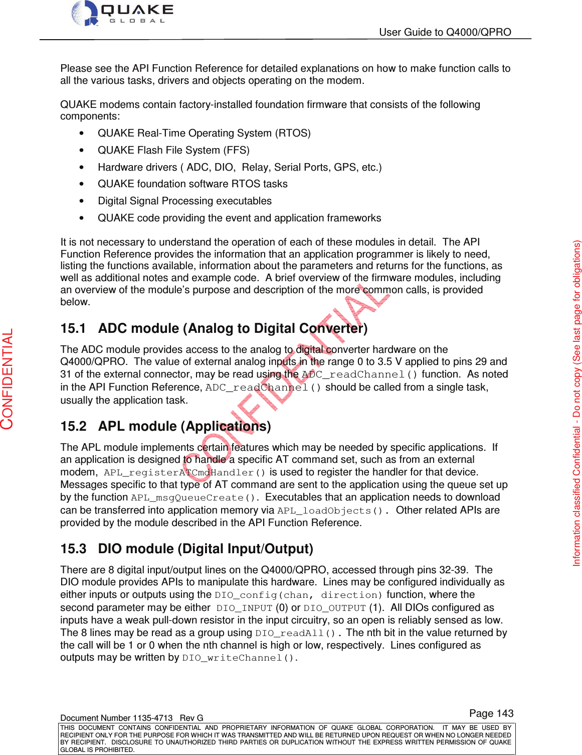
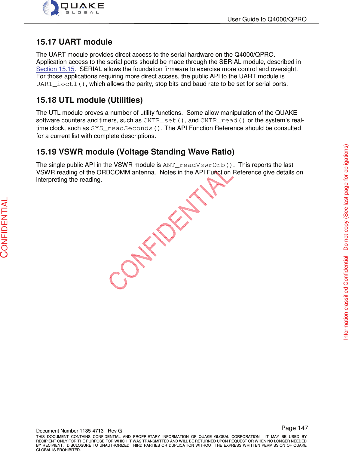
![User Guide to Q4000/QPRO Document Number 1135-4713 Rev G THIS DOCUMENT CONTAINS CONFIDENTIAL AND PROPRIETARY INFORMATION OF QUAKE GLOBAL CORPORATION. IT MAY BE USED BY RECIPIENT ONLY FOR THE PURPOSE FOR WHICH IT WAS TRANSMITTED AND WILL BE RETURNED UPON REQUEST OR WHEN NO LONGER NEEDED BY RECIPIENT. DISCLOSURE TO UNAUTHORIZED THIRD PARTIES OR DUPLICATION WITHOUT THE EXPRESS WRITTEN PERMISSION OF QUAKE GLOBAL IS PROHIBITED. Page 140 CONFIDENTIAL Information classified Confidential - Do not copy (See last page for obligations) 14.25 SPEED_ALARM A GPS measurement completed and a speed violation occurred. The parameter [0-15] indicates which Sensor Table was used. 14.26 TIMER This occurs when a software timer expires. The parameter [0-39] indicates which timer expired. Timers may be set, examined and read using function calls such as TIMER_set(), TIMER_clear(), TIMER_checkWakeup(), TIMER_setDuration() and TIMER_getRemaining(). Note that in making calls to the timer utilities, a particular timer must be selected. It is important to select a timer with the appropriate type for the intended use. The types and properties of all timers are shown in Table 14-1. Table 14-1: Timer types and properties TimerNumbersTimer TypeDescription / Notes0 - 9VolatileValue and status of these timers are lost when the modem powers down. These timers should be used for general purpose timing requirements. On power-up, all Volatile timers are set to disabled.10 - 19Non-VolatileValue and status of these timers are stored in NVM. This type of timer is used when timing data relating to an event or action must be maintained during power off. When a Non-Volatile timer expires, it does not cause a wake up of the modem, but does cause a timer event to be sent to the application on the next power on.20 - 29Wake-UpWake-up timers are like nonvolatile timers, except that when a power down is called, the Real-Time Clock (RTC) is programmed to wake up at the timer expiration time (if this time is less than the specified power down interval).30 - 39Time-Of-DayThese timers are identical to Wake-Up timers, except that the duration of the timer is specified as an absolute time of day rather than relative to the current time. Time-Of-Day Timers always expire within 24 hours.14.27 TIME_SYNC The time has been received from a source such as a satellite or GSM and the real-time clock has been updated to the new time. Parameter one is the value of the change and should be converted to a signed 32 value to ensure negative adjustments are accounted for.](https://usermanual.wiki/Quake-Global/96XXCS.Full-Manual-part-6/User-Guide-1626637-Page-1.png)
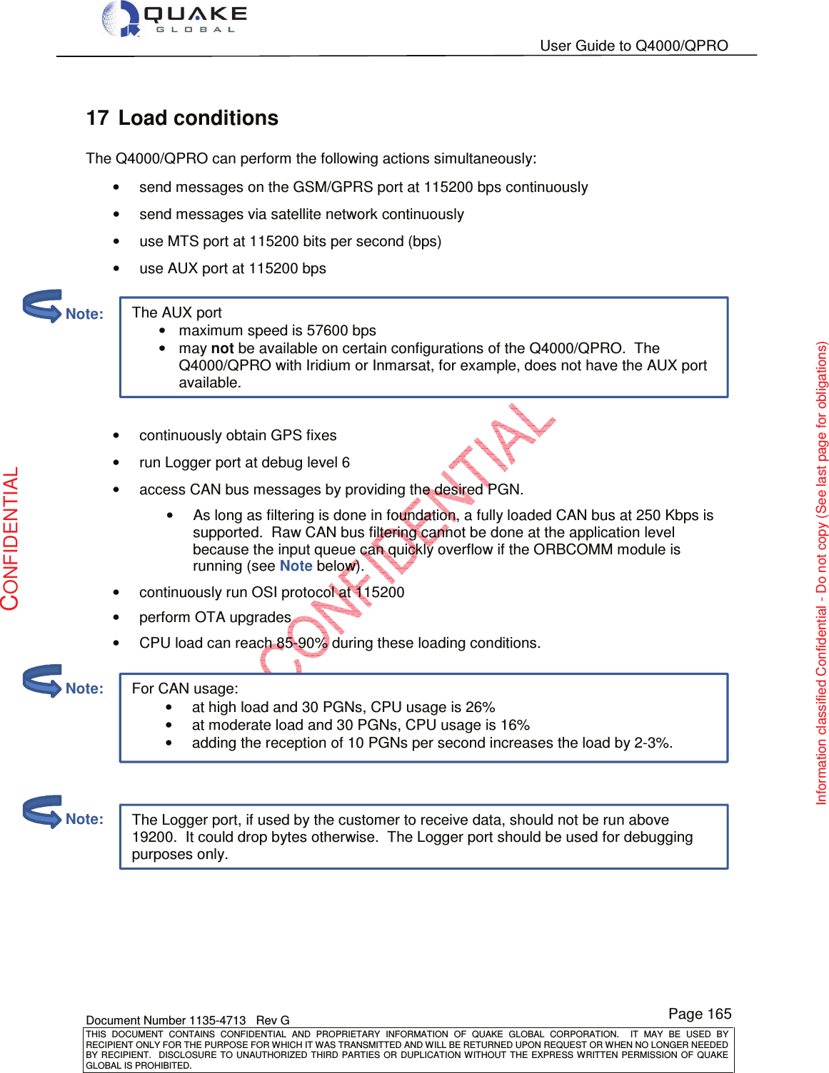
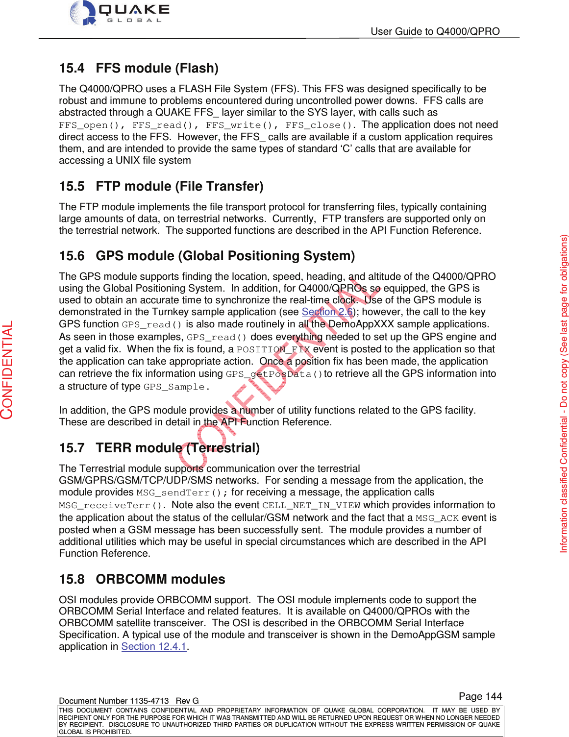
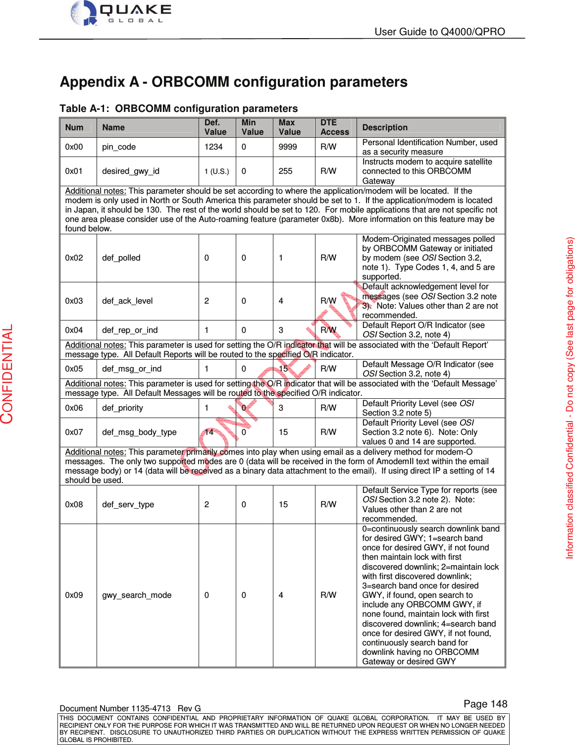
![User Guide to Q4000/QPRO Document Number 1135-4713 Rev G THIS DOCUMENT CONTAINS CONFIDENTIAL AND PROPRIETARY INFORMATION OF QUAKE GLOBAL CORPORATION. IT MAY BE USED BY RECIPIENT ONLY FOR THE PURPOSE FOR WHICH IT WAS TRANSMITTED AND WILL BE RETURNED UPON REQUEST OR WHEN NO LONGER NEEDED BY RECIPIENT. DISCLOSURE TO UNAUTHORIZED THIRD PARTIES OR DUPLICATION WITHOUT THE EXPRESS WRITTEN PERMISSION OF QUAKE GLOBAL IS PROHIBITED. Page 141 CONFIDENTIAL Information classified Confidential - Do not copy (See last page for obligations) 14.28 USER_CMD An Over-The-Air command was received. The parameter [0-255] indicates which action to take. This is currently supported for ORBCOMM and GSM/GPRS networks. When a USER_CMD is sent, byte 0 of the data represents how many user commands will be sent. This is based on User Data Bytes 1-4 content in conjunction with User Byte 0’s value. For example, using: USER DATA BYTES 0 1 2 3 4 Example. 1: If the data bytes sent were 0x01 0xFF 0x00 0x00 0x00 • One USER_CMD event would be sent to the application. • It would be USER_CMD 255. • Notice that User Data Bytes 2-4 have no meaning. Example. 2: If the data bytes sent were 0x02 0xFF 0x00 0x00 0x00 • Two USER_CMD events would be sent to the application. • They would be USER_CMD 255 and USER_CMD 0. • In this case User Data Bytes 3 and 4 have no meaning. Example. 3: If the data bytes sent were 0x03 0x01 0x02 0x03 0x00 • Three USER_CMD events would be sent to the application. • They would be USER_CMD 0, USER_CMD 1 and USER_CMD 3. • In this case User Byte 4 has no meaning. Example. 4: If the data bytes sent were 0x04 0x01 0x02 0x03 0x0A • Four USER_CMD events would be sent to the application. • They would be USER_CMD 1, USER_CMD 2, USER_CMD 3, and USER_CMD 10.](https://usermanual.wiki/Quake-Global/96XXCS.Full-Manual-part-6/User-Guide-1626637-Page-2.png)
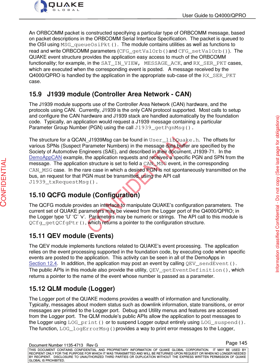
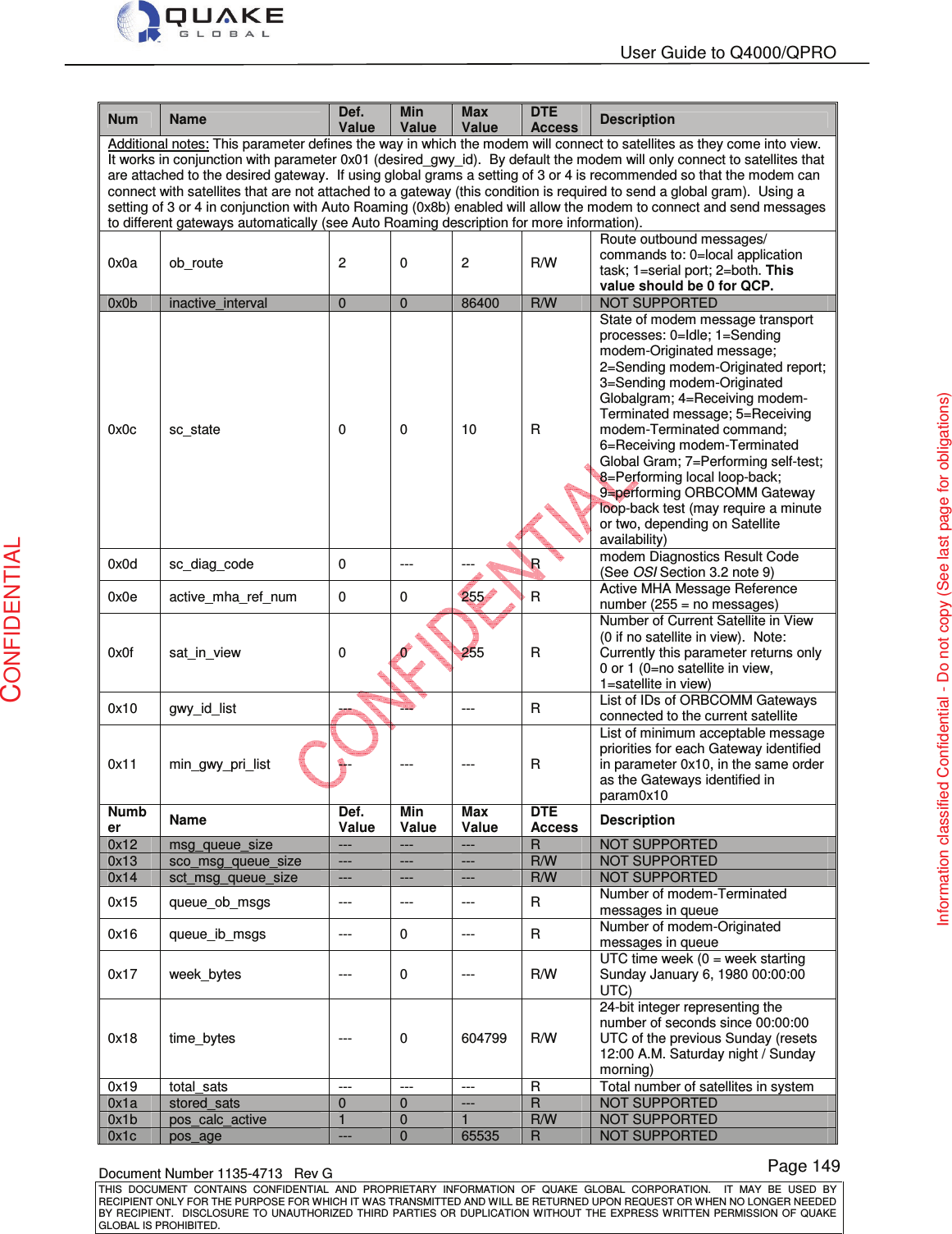
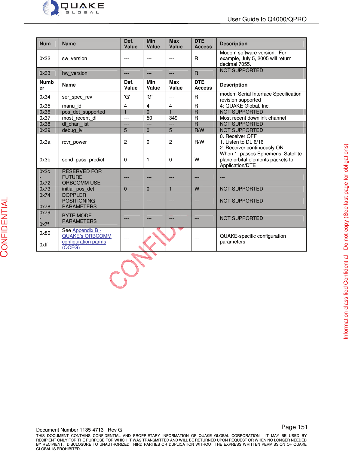
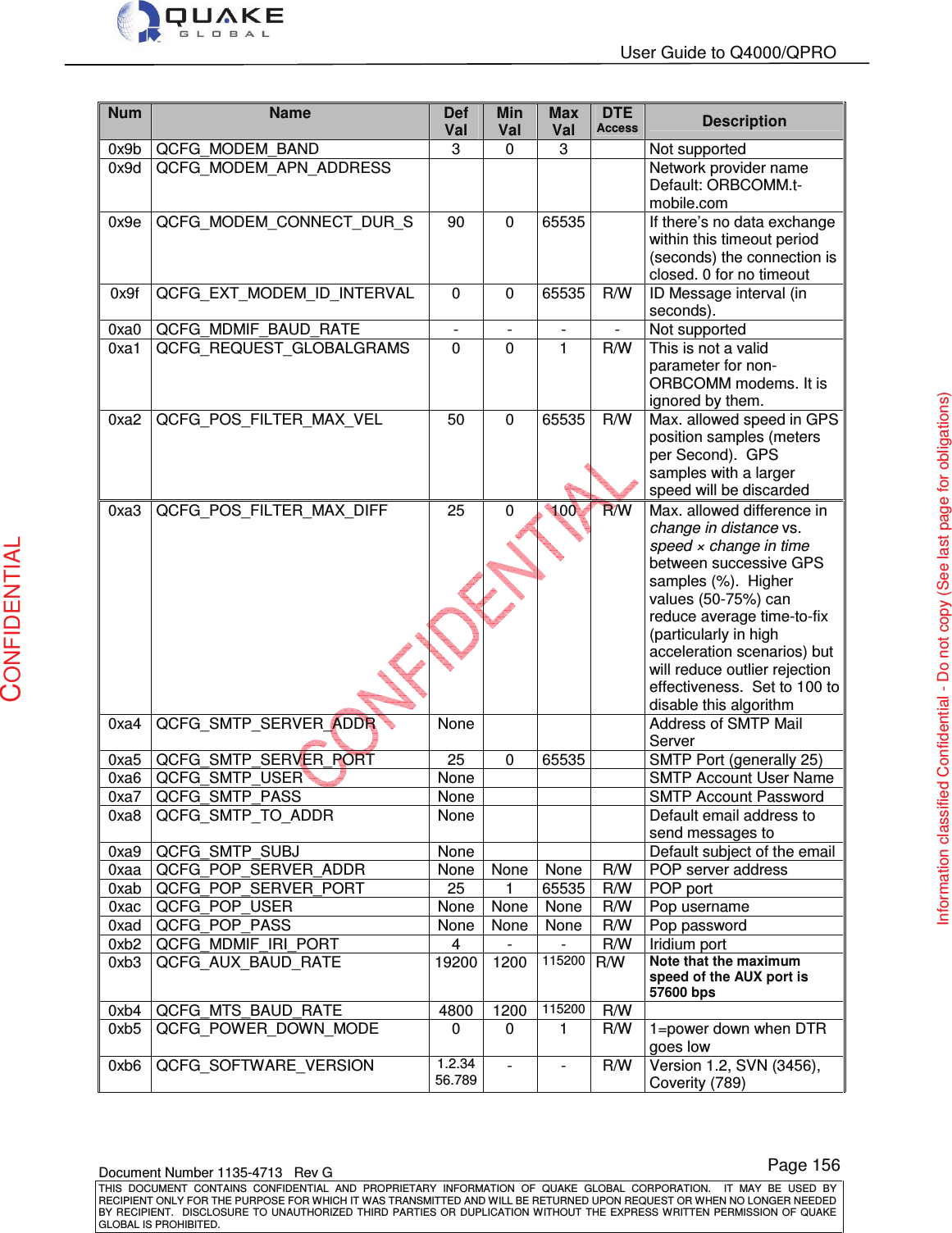
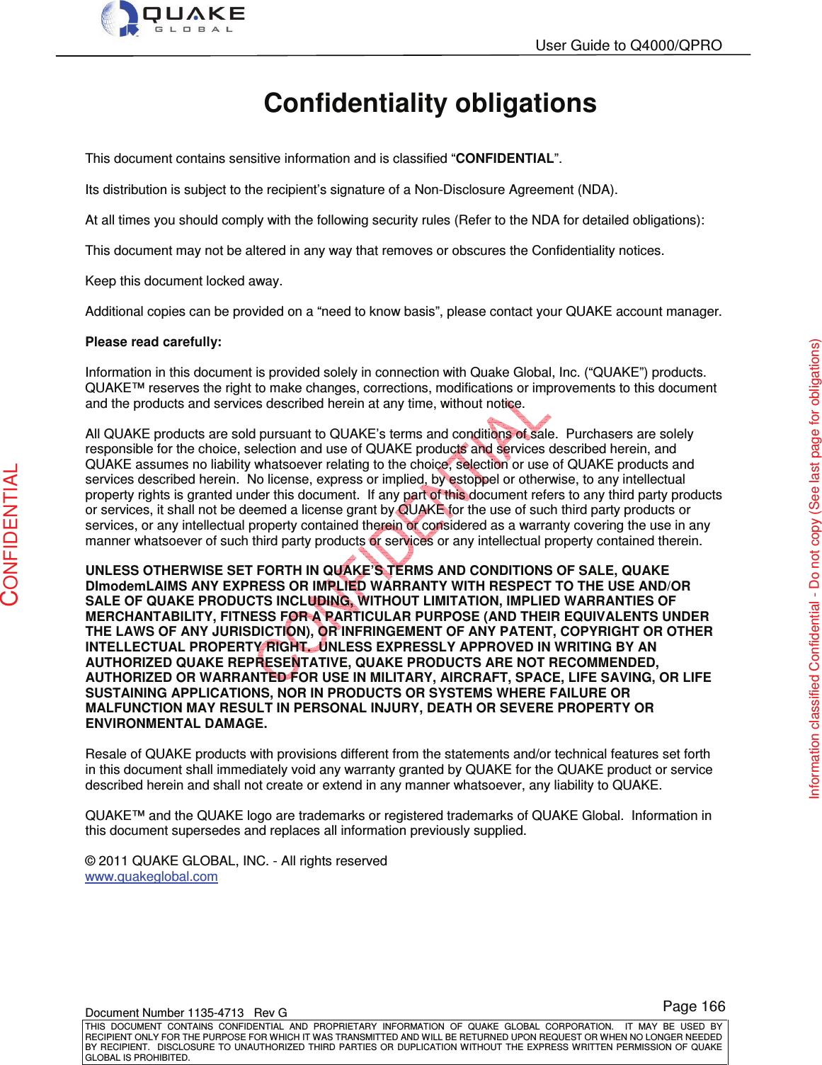
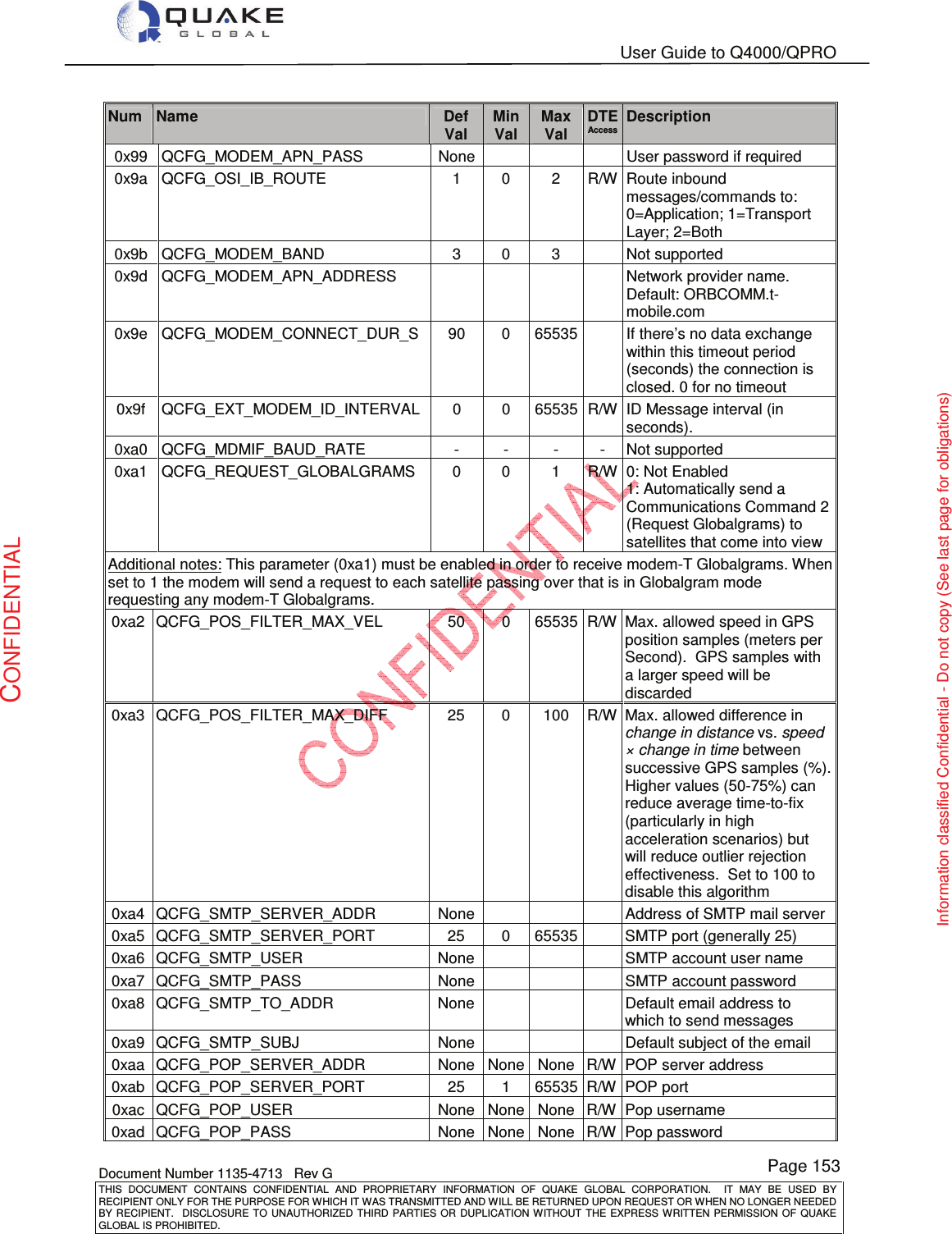
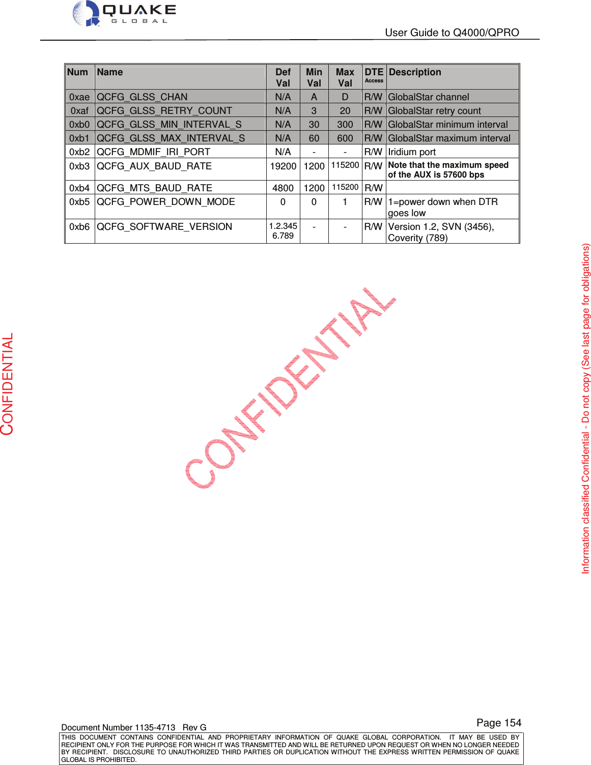
![User Guide to Q4000/QPRO Document Number 1135-4713 Rev G THIS DOCUMENT CONTAINS CONFIDENTIAL AND PROPRIETARY INFORMATION OF QUAKE GLOBAL CORPORATION. IT MAY BE USED BY RECIPIENT ONLY FOR THE PURPOSE FOR WHICH IT WAS TRANSMITTED AND WILL BE RETURNED UPON REQUEST OR WHEN NO LONGER NEEDED BY RECIPIENT. DISCLOSURE TO UNAUTHORIZED THIRD PARTIES OR DUPLICATION WITHOUT THE EXPRESS WRITTEN PERMISSION OF QUAKE GLOBAL IS PROHIBITED. Page 152 CONFIDENTIAL Information classified Confidential - Do not copy (See last page for obligations) Appendix B - QUAKE’s ORBCOMM configuration parms (QCFG) Table B-1: QUAKE’s ORBCOMM configuration parameters Num Name Def Val Min Val Max Val DTE Access Description 0x80 QCFG_LOG_DEBUG_LEVEL 4 0 6 R/W Logger Port log level 0x81 QCFG_GPS_LOGGING 0 0 1 R/W GPS Task debug logging enable 0x82 QCFG_TL_LOGGING 0 0 1 R/W 0: Not enabled 1: Enable Transport Layer debug logging (must be set for prms 0x83-0x88 to take effect) 0x83 QCFG_DLEVPROC_LOG_LEVEL 0 0 5 R/W Downlink Event Proc Task debug level 0x84 QCFG_ULMGR_LOG_LEVEL 0 0 5 R/W Uplink Mgr Task debug level 0x85 QCFG_SPP_LOG_LEVEL 0 0 5 R/W Serial Pkt Proc Task debug level 0x86 QCFG_MODEM-TMGR_LOG_LEVEL 0 0 5 R/W modem-T Msg Mgr Task debug level 0x87 QCFG_MODEM_LOG_LEVEL 0 0 5 R/W TL modem Task debug level 0x88 QCFG_OSPM_LOG_LEVEL 0 0 5 R/W OB Serial Pkt Mgr Task debug level 0x89 QCFG_MSN_SAVE_OPTION 0 0 1 R/W 0: Save MSN data to flash on [controlled] power down only 1: Save MSN data to flash on any change 0x8b QCFG_MTS_AUTO_ROAMING_ENA 0 0 1 R/W 0: Not enabled 1: Enable Auto-Roaming for message packets received on MTS Port 0x8c QCFG_QLM_LOG_MASK - - - - Not supported 0x8d QCFG_DUPL_USR_CMD_TIME_S 900 30 3600 R/W Number of seconds for which User Command duplicates will be discarded 0x8e QCFG_POWER_SAVING_MASK - - - - Not supported 0x90 QCFG_PREF_NETWORK 0 0 3 0 – GSM first 1 – ORBCOMM first 2 – GSM only 3 – ORBCOMM only 0x92 QCFG_MDMIF_PORT 3 0 3 Do not change 0x94 QCFG_DBG_UTILITY_LEVEL 5 0 5 R/W Debug mode log level 0x95 QCFG_MTS_ARCHIVING_ENA 0 0 1 R/W 0: Not enabled 1: Enable message archiving to flash memory of message packets received on MTS port Additional notes: When this parameter is enabled modem-O messages will be stored in NVM. If the modem loses power or is put into sleep mode it will retrieve any unsent messages at boot up and return them to the message queue. 0x98 QCFG_MODEM_APN_USER None User login name if required](https://usermanual.wiki/Quake-Global/96XXCS.Full-Manual-part-6/User-Guide-1626637-Page-13.png)
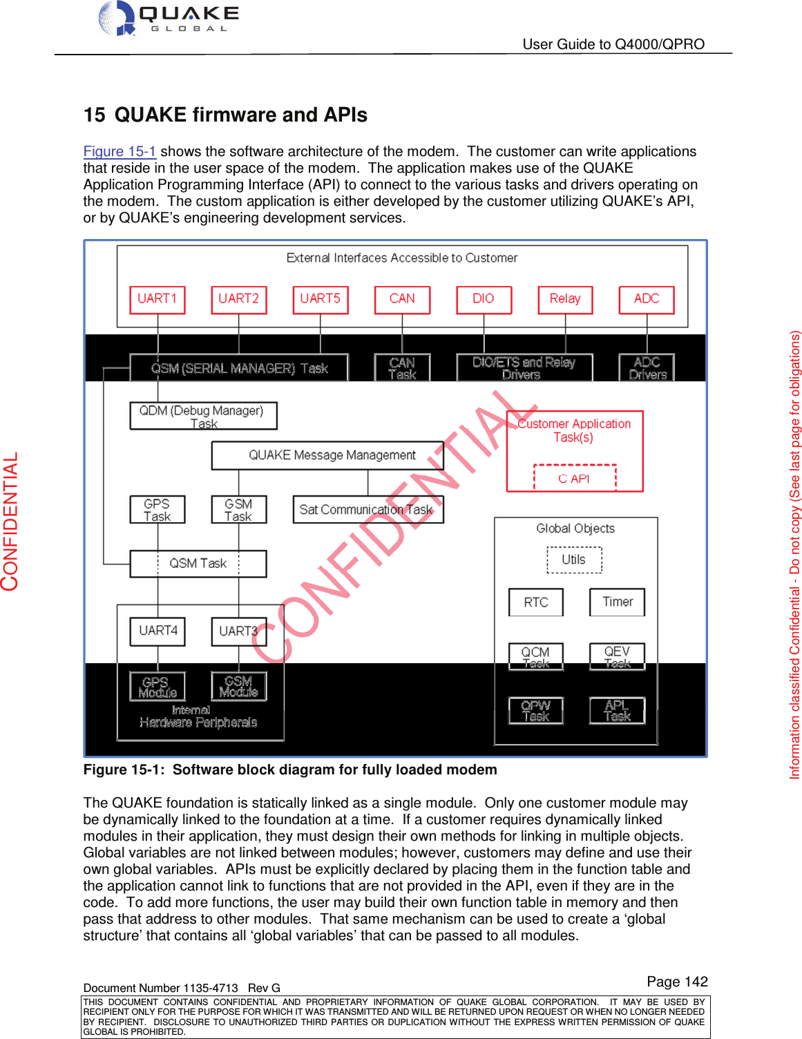
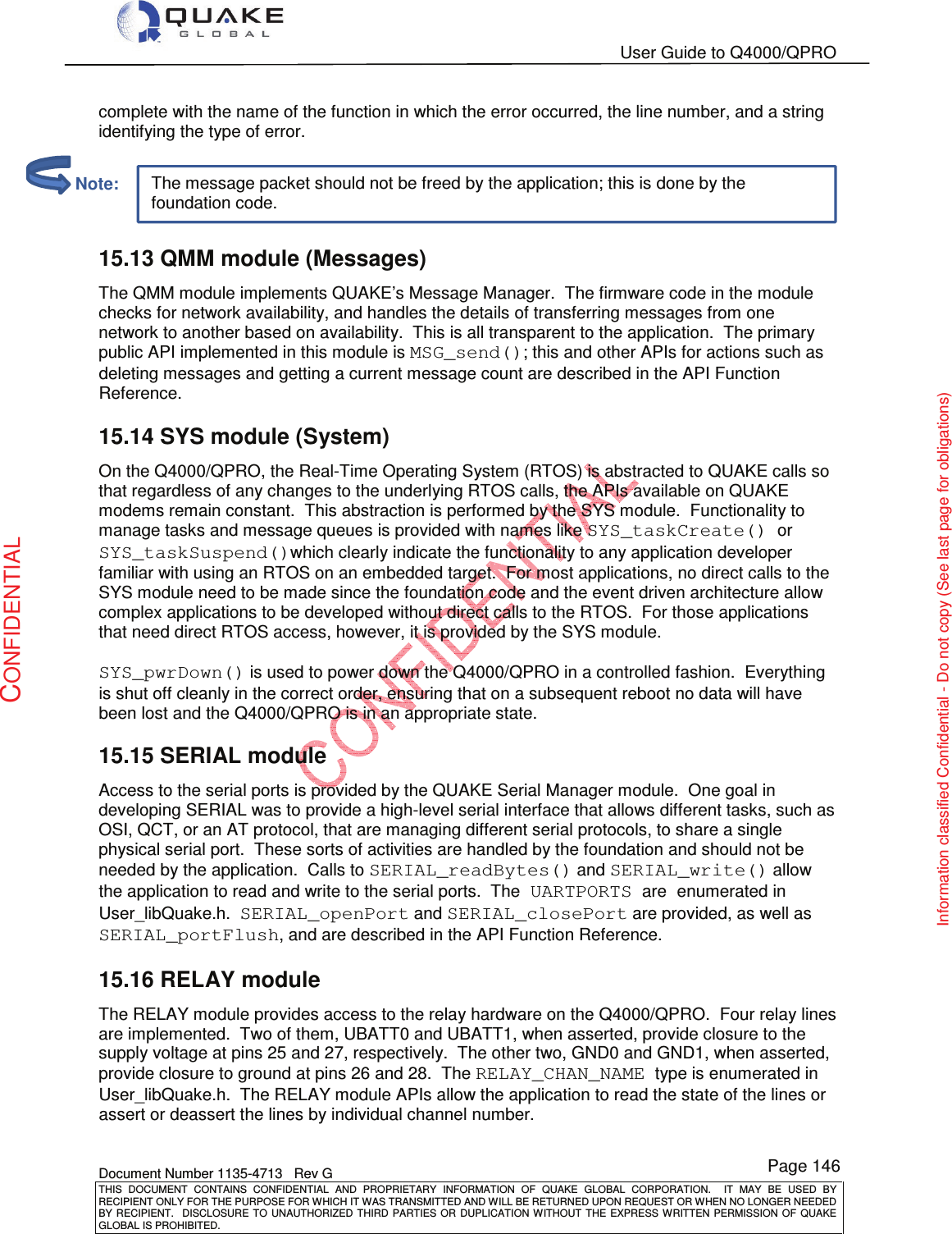
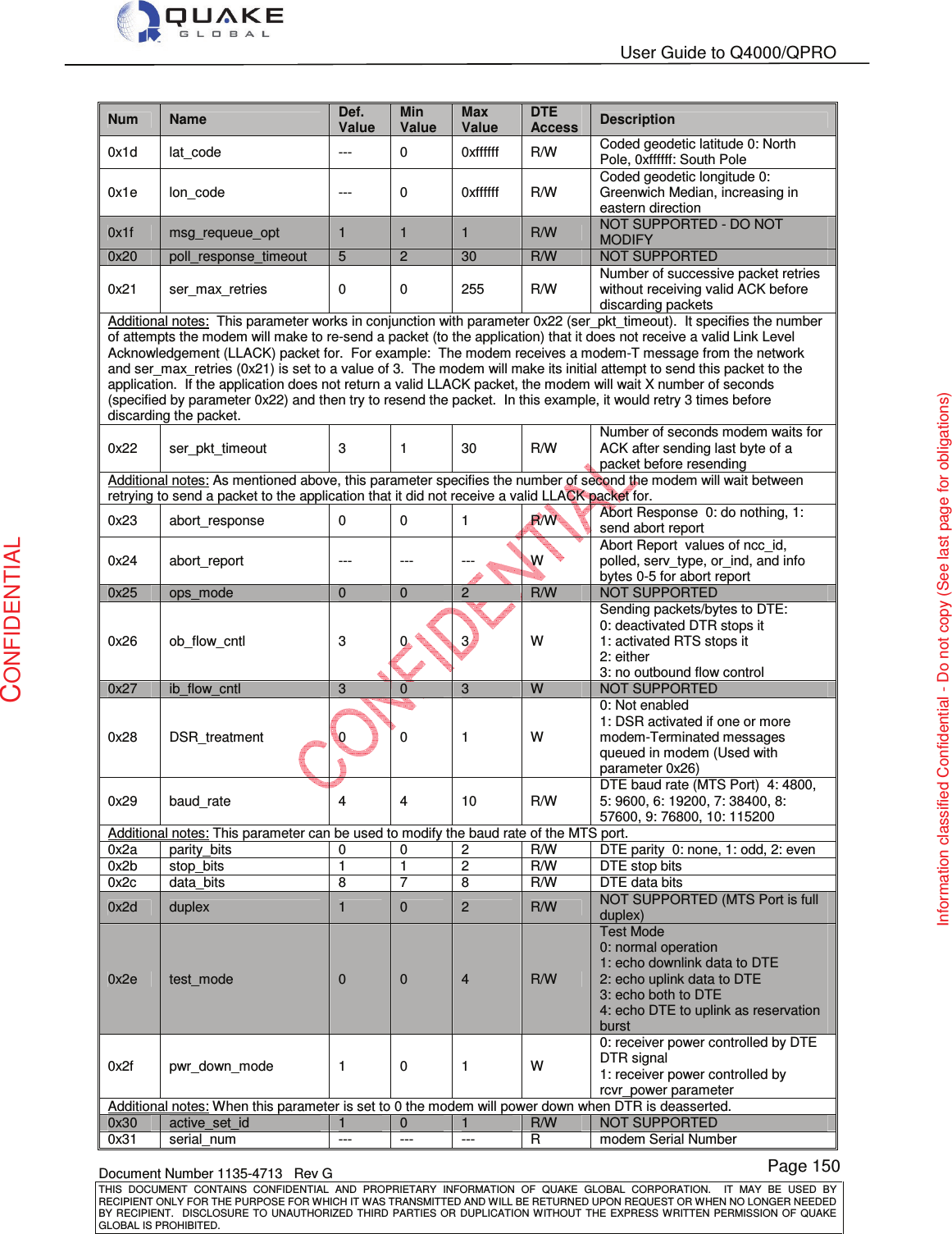
![User Guide to Q4000/QPRO Document Number 1135-4713 Rev G THIS DOCUMENT CONTAINS CONFIDENTIAL AND PROPRIETARY INFORMATION OF QUAKE GLOBAL CORPORATION. IT MAY BE USED BY RECIPIENT ONLY FOR THE PURPOSE FOR WHICH IT WAS TRANSMITTED AND WILL BE RETURNED UPON REQUEST OR WHEN NO LONGER NEEDED BY RECIPIENT. DISCLOSURE TO UNAUTHORIZED THIRD PARTIES OR DUPLICATION WITHOUT THE EXPRESS WRITTEN PERMISSION OF QUAKE GLOBAL IS PROHIBITED. Page 155 CONFIDENTIAL Information classified Confidential - Do not copy (See last page for obligations) Appendix C - QUAKE’s Iridium & Inmarsat config parms (QCFG) Table C-1: QUAKE’s Iridium and Inmarsat configuration parameters Num Name Def Val Min Val Max Val DTE Access Description 0x80 QCFG_LOG_DEBUG_LEVEL 4 0 6 Level of logging messages output 0x81 QCFG_GPS_LOGGING 0 0 1 R/W GPS Task debug logging enable 0x82 QCFG_TL_LOGGING 0 0 1 R/W 0: Not enabled 1: Enable Transport Layer debug logging (must be set for prms 0x83-0x88 to take effect) 0x83 QCFG_DLEVPROC_LOG_LEVEL 0 0 5 R/W Downlink Event Proc Task debug level 0x84 QCFG_ULMGR_LOG_LEVEL 0 0 5 R/W Uplink Mgr Task debug level 0x85 QCFG_SPP_LOG_LEVEL 0 0 5 R/W Serial Pkt Proc Task debug level 0x86 QCFG_MODEM-TMGR_LOG_LEVEL 0 0 5 R/W modem-T Msg Mgr Task debug level 0x87 QCFG_MODEM_LOG_LEVEL 0 0 5 R/W TL modem Task debug level 0x88 QCFG_OSPM_LOG_LEVEL 0 0 5 R/W OB Serial Pkt Mgr Task debug level 0x89 QCFG_MSN_SAVE_OPTION 0 0 1 R/W 0: Save MSN data to flash on [controlled] power down only 1: Save MSN data to flash on any change 0x8b QCFG_MTS_AUTO_ROAMING_ENA 0 0 1 R/W 0: Not enabled 1: Enable Auto-Roaming for message packets received on MTS Port 0x8c QCFG_QLM_LOG_MASK - - - - Not supported 0x8d QCFG_DUPL_USR_CMD_TIME_S 900 30 3600 R/W Number of Seconds for which User Command duplicates will be discarded 0x8e QCFG_POWER_SAVING_MASK - - - - Not supported 0x90 QCFG_PREF_NETWORK 0 0 3 0 – GSM first 1 – Sat first 2 – GSM only 3 – Sat only 0x92 QCFG_MDMIF_PORT 3 0 4 0x94 QCFG_DBG_UTILITY_LEVEL 5 0 5 R/W Debug Mode log level 0x95 QCFG_MTS_ARCHIVING_ENA 0 0 1 R/W 0: Not enabled 1: Enable Message Archiving to flash memory of msg packets received on the MTS Port Additional notes: When this parameter is enabled, modem-O msgs will be stored in NVM. If the modem loses power or is put into sleep mode it will retrieve any unsent msgs at boot up and return them to the msg queue. 0x98 QCFG_MODEM_APN_USER None User login name if required 0x99 QCFG_MODEM_APN_PASS None User password if required](https://usermanual.wiki/Quake-Global/96XXCS.Full-Manual-part-6/User-Guide-1626637-Page-16.png)