Quake Global 96XXCS Q4000 / QPRO Satellite Module User Manual 1135 4713G GREEN Users Guide to Q4000 QPRO
Quake Global Inc. Q4000 / QPRO Satellite Module 1135 4713G GREEN Users Guide to Q4000 QPRO
UserManual.wiki
>
Quake Global
>
96XXCS User Manual
>
Full Manual part 1
Contents
1.
Datasheet QPRO
2.
Full Manual part 2
3.
Full Manual part 3
4.
Full Manual part 5
5.
Full Manual part 7
6.
Datasheet Q4000
7.
Full Manual part 1
8.
Full Manual part 4
9.
Full Manual part 6
Full Manual part 1
Navigation menu
Upload a User Manual
Namespaces
Wiki Guide
HTML
PDF
Info
Views
User Manual
Discussion / Help
Navigation

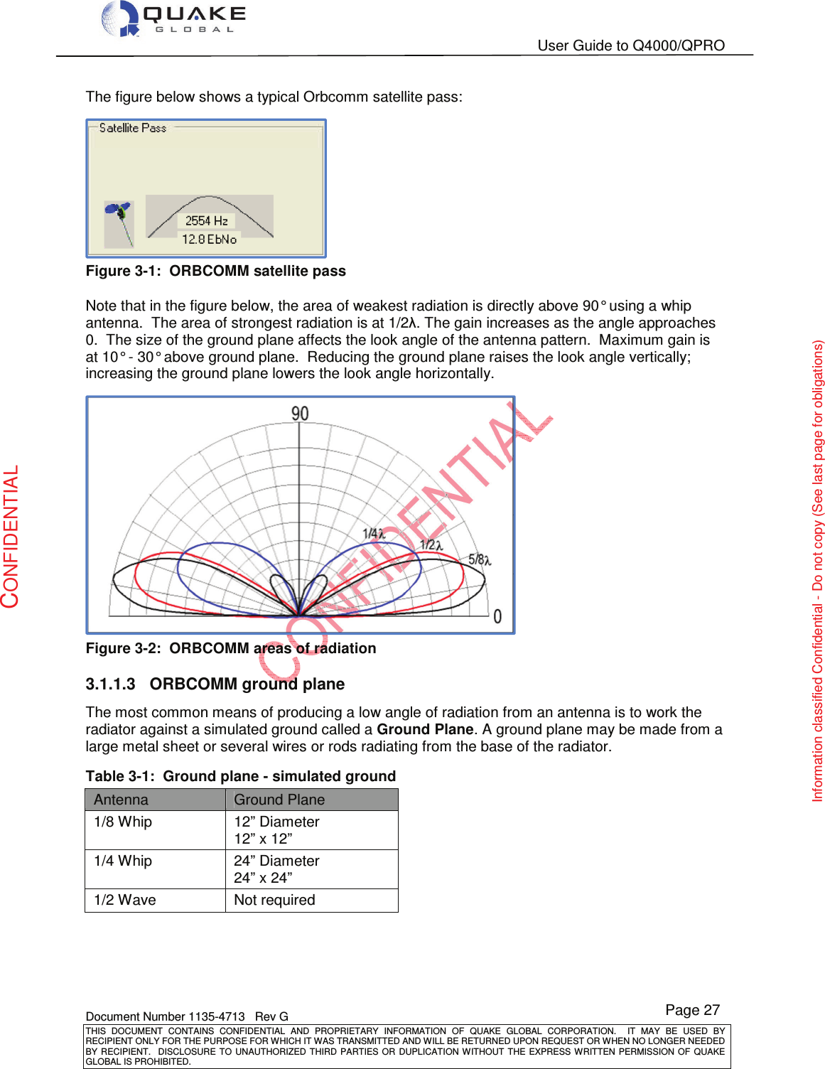
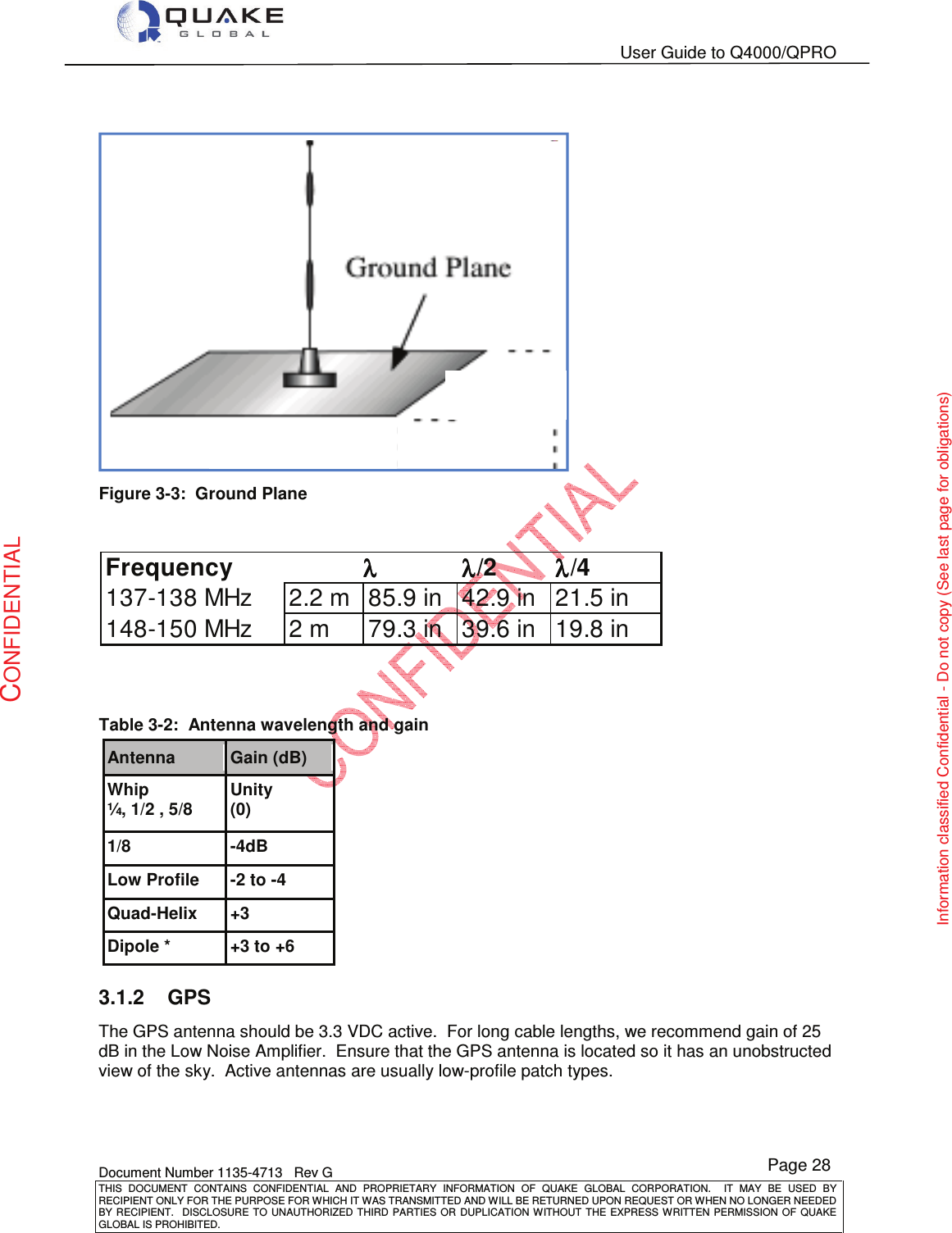
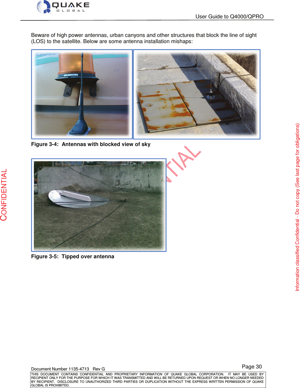
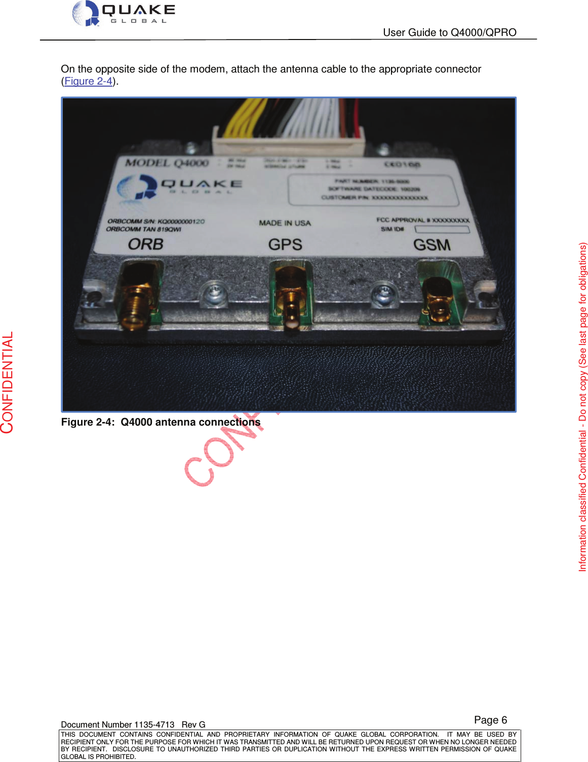
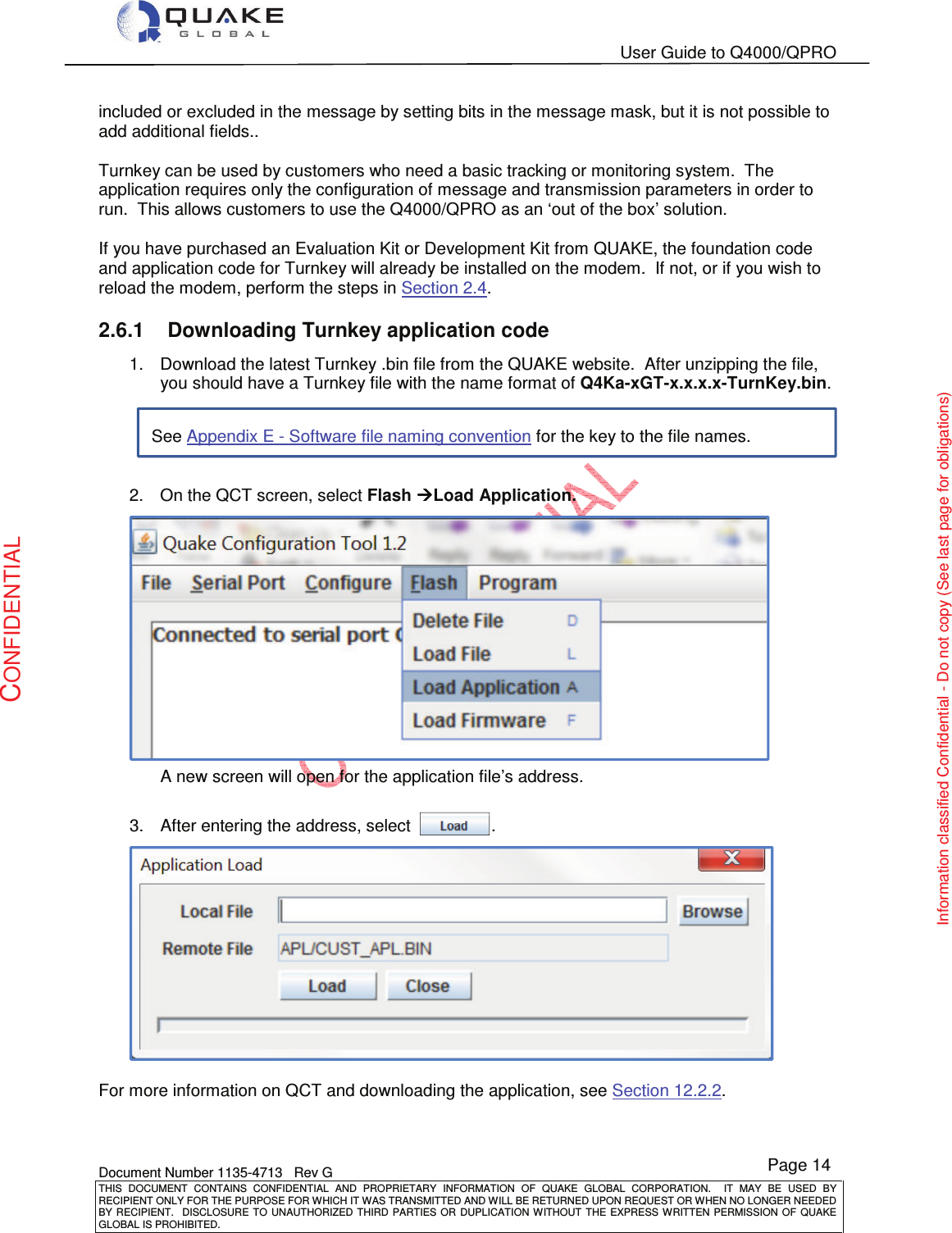
![User Guide to Q4000/QPRO Document Number 1135-4713 Rev G THIS DOCUMENT CONTAINS CONFIDENTIAL AND PROPRIETARY INFORMATION OF QUAKE GLOBAL CORPORATION. IT MAY BE USED BY RECIPIENT ONLY FOR THE PURPOSE FOR WHICH IT WAS TRANSMITTED AND WILL BE RETURNED UPON REQUEST OR WHEN NO LONGER NEEDED BY RECIPIENT. DISCLOSURE TO UNAUTHORIZED THIRD PARTIES OR DUPLICATION WITHOUT THE EXPRESS WRITTEN PERMISSION OF QUAKE GLOBAL IS PROHIBITED. Page 2 CONFIDENTIAL Information classified Confidential - Do not copy (See last page for obligations) Chapter 11: OVER THE AIR UPDATE describes how to update the modem’s firmware remotely using satellite and GSM. Chapter 12: EVENT DRIVEN ARCHITECTURE discusses the various events that make up the software architecture of the Q4000/QPRO modem. Chapter 13: QUAKE FIRMWARE AND API’S discusses the main modules of the modem foundation software and their interactions. Appendix A - ORBCOMM configuration parameters Appendix B - QUAKE’s ORBCOMM configuration parameters (QCFG) Appendix C - QUAKE’s Iridium & Inmarsat configuration parameters (QCFG). Appendix D - Debug and utility menus Appendix E - Software file naming convention Appendix F - Glossary of terms CONFIDENTIALITY OBLIGATIONS. 1.3 Related documents The following documents contain valuable information: [1] 1135-0902, Technical Data Sheet Q4000 [2] 1137-0901, Technical Data Sheet QPRO [3] Q4000/QPRO API Function Reference – From QUAKE Global Website [4] 1135-4711 QUAKE Configuration Tool (QCT) [5] 1135-4715 QUAKE Communications Protocol (QCP) User Manual For Q4000/QPROs with an ORBCOMM satellite transceiver installed, the following ORBCOMM documentation may assist in application development (see www.ORBCOMM.com) [6] ORBCOMM Serial Interface Specification, Rev. G or greater [7] ORBCOMM Gateway Customer Access Interface Specification, Rev. C or greater [8] ORBCOMM Messaging Services Description [9] ORBCOMM Application Development for Roaming Phase 1 For Q4000/QPROs with an Iridium satellite transceiver installed, the following Iridium documentation may assist in application development (see www.iridium.com) [10] Iridium SBD Developer’s Guide [11] 4000-3000 Rev. D. AT Command Set Manual For Q4000/QPROs with an Inmarsat satellite transceiver installed, the following Inmarsat documentation may assist in application development (see www.skywave.com) [12] N200_IsatData_Pro_Network_services_Overview [13] N201_IsatData_Pro_Tateway_Web_service_User_Guide [14] T203_IDP_100_Modem_series_developers_Guide](https://usermanual.wiki/Quake-Global/96XXCS.Full-Manual-part-1/User-Guide-1626632-Page-13.png)
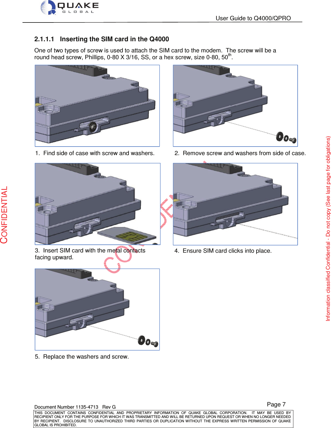
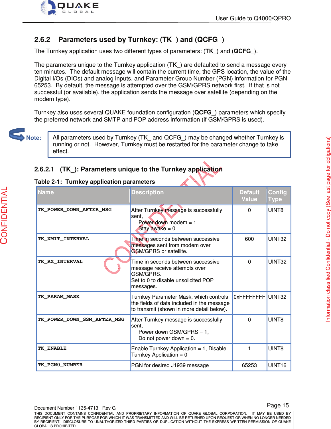
![User Guide to Q4000/QPRO Document Number 1135-4713 Rev G THIS DOCUMENT CONTAINS CONFIDENTIAL AND PROPRIETARY INFORMATION OF QUAKE GLOBAL CORPORATION. IT MAY BE USED BY RECIPIENT ONLY FOR THE PURPOSE FOR WHICH IT WAS TRANSMITTED AND WILL BE RETURNED UPON REQUEST OR WHEN NO LONGER NEEDED BY RECIPIENT. DISCLOSURE TO UNAUTHORIZED THIRD PARTIES OR DUPLICATION WITHOUT THE EXPRESS WRITTEN PERMISSION OF QUAKE GLOBAL IS PROHIBITED. Page 3 CONFIDENTIAL Information classified Confidential - Do not copy (See last page for obligations) The built-in and on-line help provided by IAR Systems for their Integrated Development Environment (IDE) are valuable references. The API Function Reference listed above [3] is necessary for any custom ‘C’ programming involving calls to supported API functions. It should be viewed as a companion piece to this document. You may obtain the most current version of this document from the QUAKE Global website at www.quakeglobal.com. 1.4 Contacting QUAKE To contact QUAKE Global Inc. regarding the QUAKE modem development environment, API, or other issues, please refer to the following information: QUAKE Global 4933 Paramount Dr San Diego CA 92123 Phone Number: (858) 277-7290 Fax Number: (858) 277-7259 Website: www.quakeglobal.com Email: customersupport@quakeglobal.com](https://usermanual.wiki/Quake-Global/96XXCS.Full-Manual-part-1/User-Guide-1626632-Page-14.png)
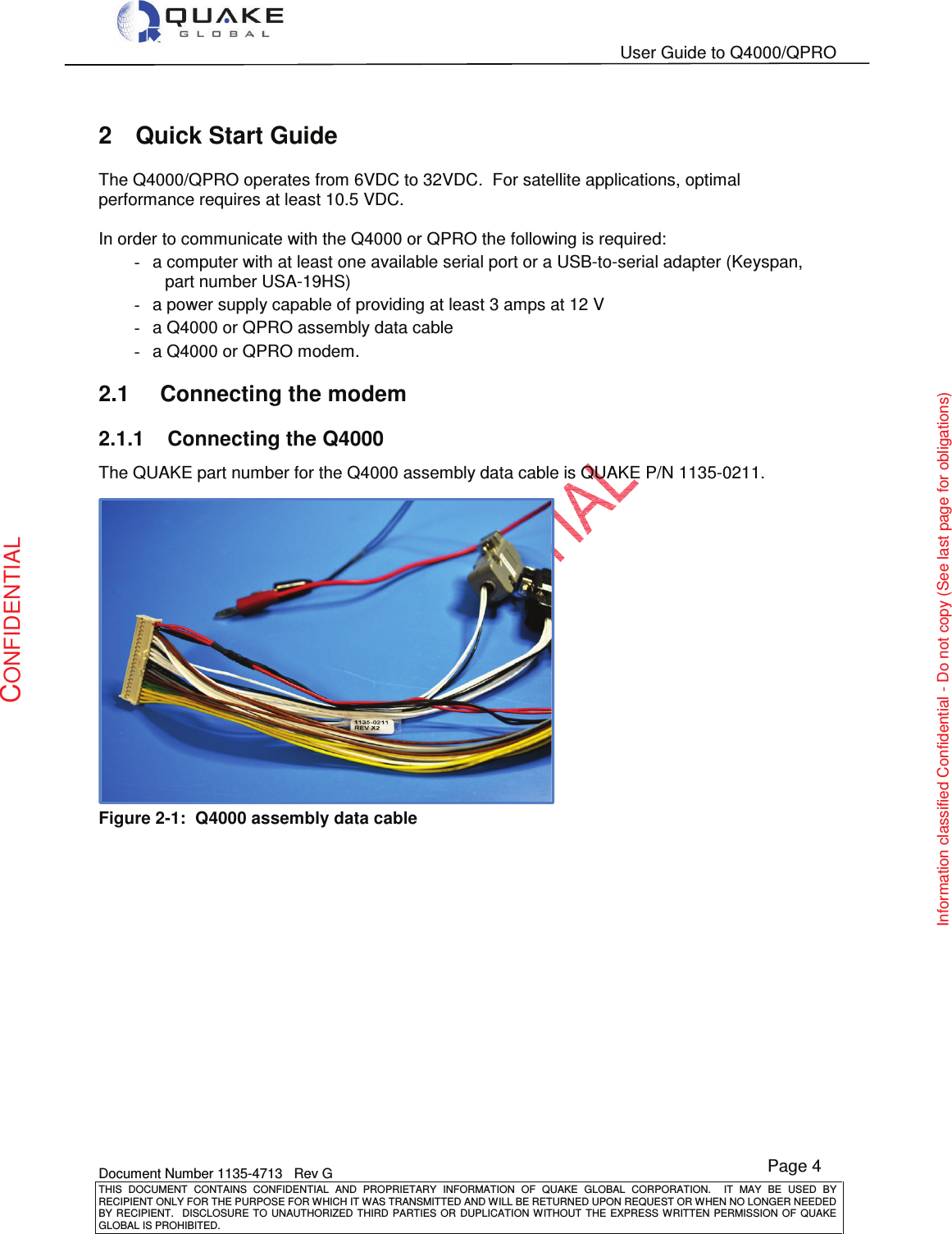
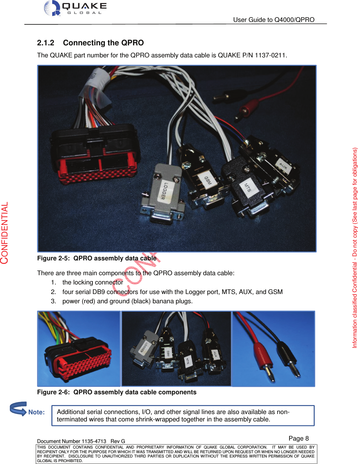
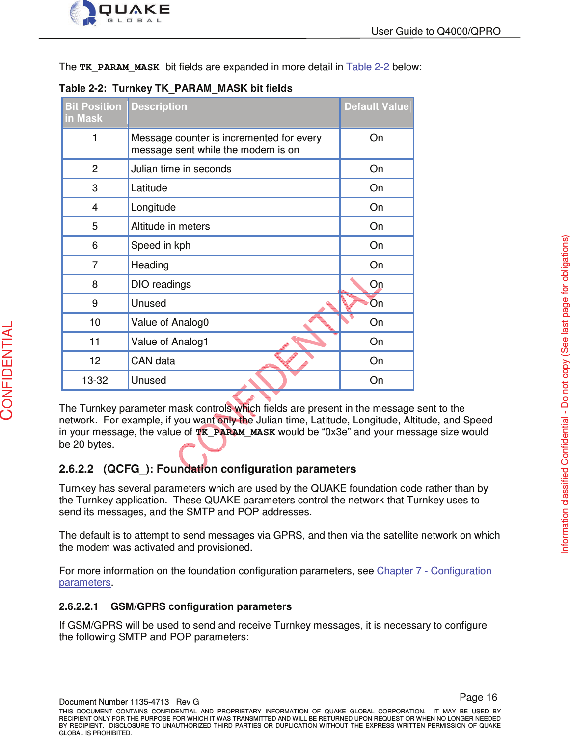

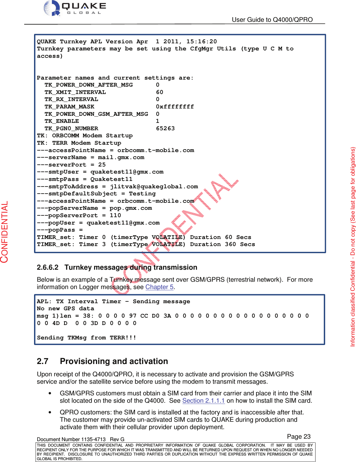
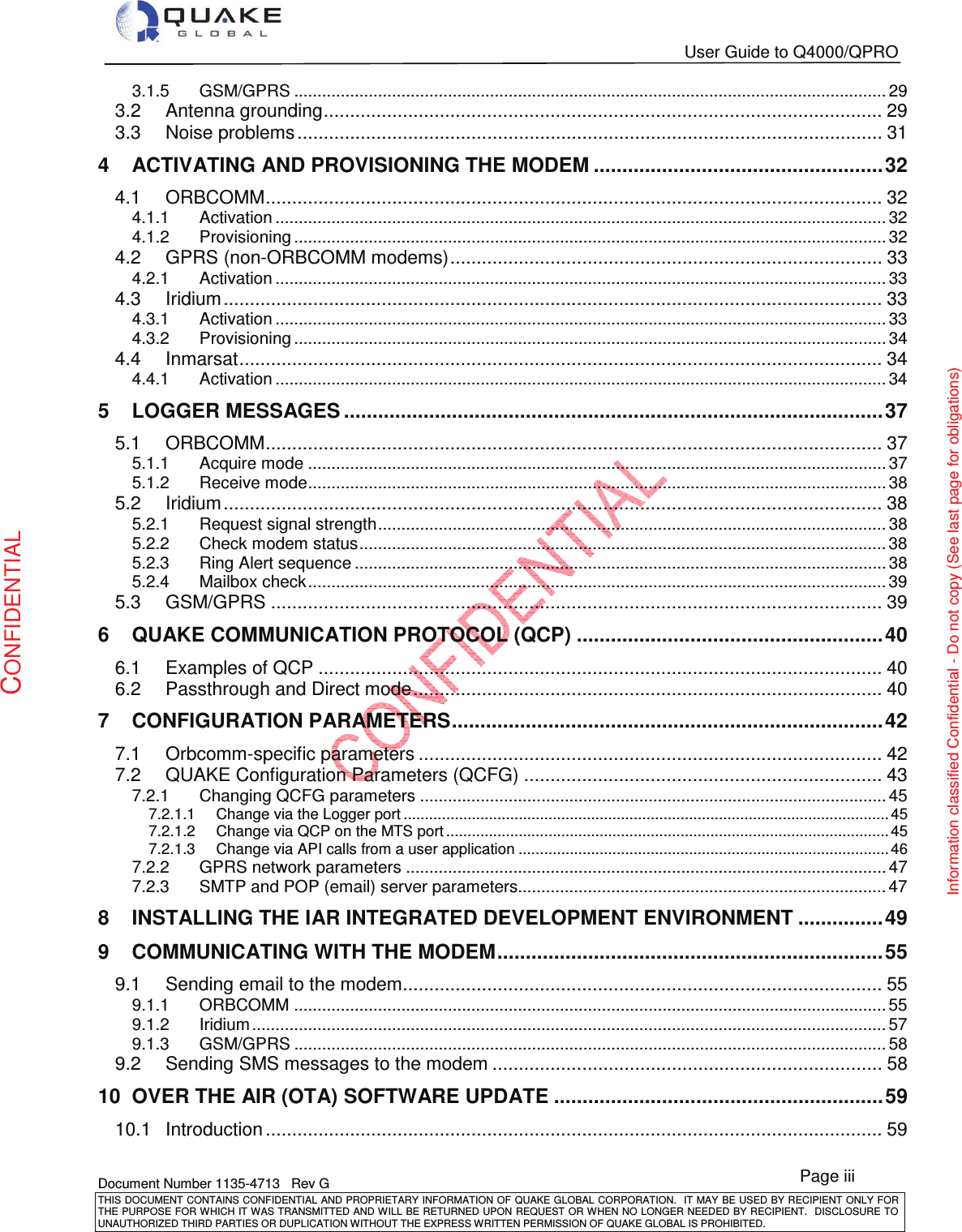
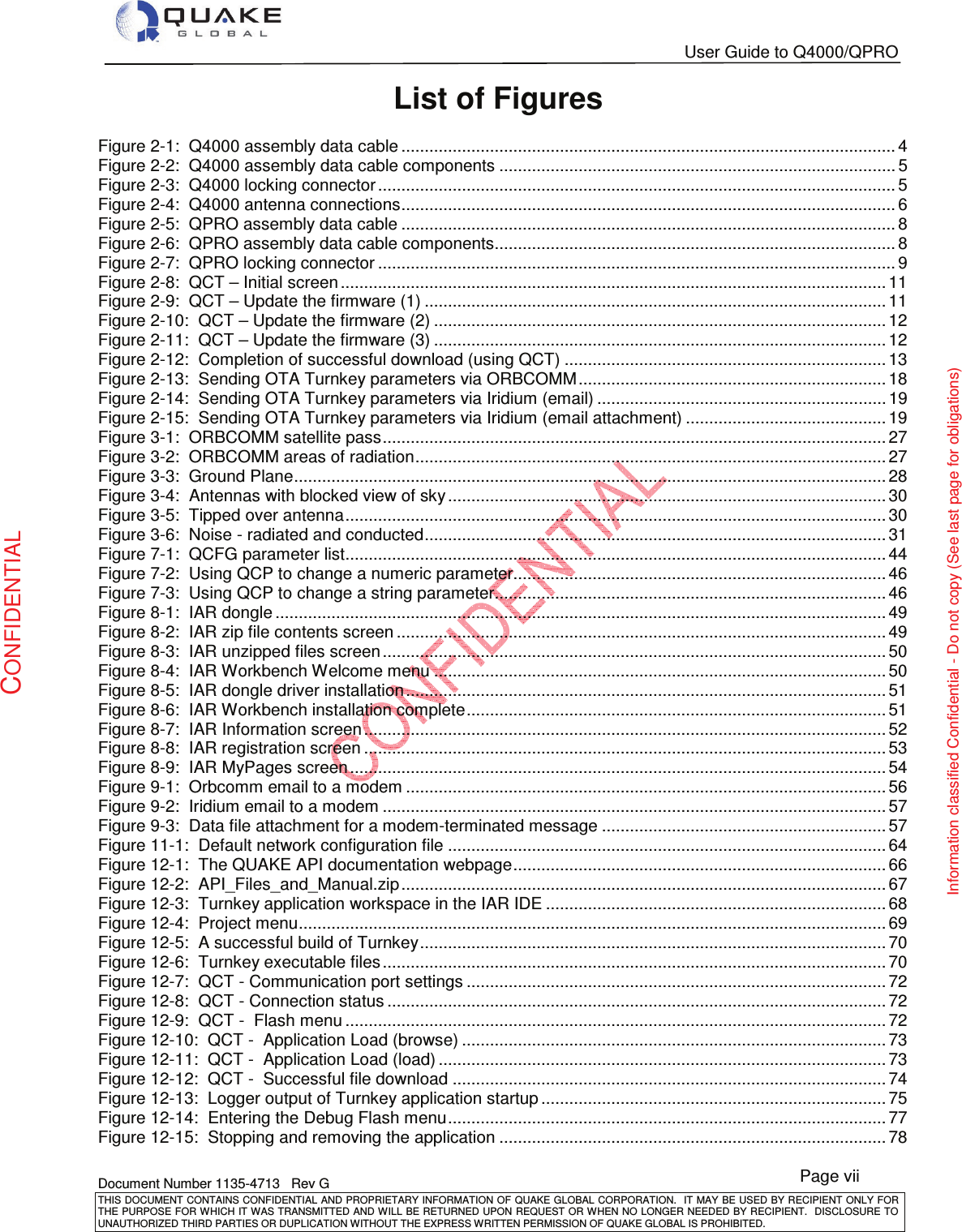
![User Guide to Q4000/QPRO Document Number 1135-4713 Rev G THIS DOCUMENT CONTAINS CONFIDENTIAL AND PROPRIETARY INFORMATION OF QUAKE GLOBAL CORPORATION. IT MAY BE USED BY RECIPIENT ONLY FOR THE PURPOSE FOR WHICH IT WAS TRANSMITTED AND WILL BE RETURNED UPON REQUEST OR WHEN NO LONGER NEEDED BY RECIPIENT. DISCLOSURE TO UNAUTHORIZED THIRD PARTIES OR DUPLICATION WITHOUT THE EXPRESS WRITTEN PERMISSION OF QUAKE GLOBAL IS PROHIBITED. Page 21 CONFIDENTIAL Information classified Confidential - Do not copy (See last page for obligations) If the bit value in TK_PARAM_MASK is turned off, the associated bytes will not be in the message and the message size will change. 2.6.4 Turnkey message format The modem-originated Turnkey message has the following format if all the fields in the TK_PARAM_MASK are set (0xFFFFFFFF): Table 2-4: Turnkey message format Size Field Name Description 4 messageCount message count 4 timeJS time of data collection in Julian seconds 4 gpsLatitude latitude 4 gpsLongitude longitude 4 gpsAltitude altitude in meters 4 gpsSpeed speed in kph 2 gpsHeading heading in degrees * 100 1 allDig all 8 digital inputs 1 spare0 spare input 0 4 ana0 analog0 4 ana1 analog1 2 canPgn0DataLen size of PGN0 data 1 canPgn0Data [MAX_NUM_J1939_DATA_BYTES] J1939 data from PGN0 2.6.5 Running the Turnkey application The Turnkey application operates as follows: 1. At power-up, a GPS fix is started. 2. When the transmit timer expires (TK_XMIT_INTERVAL), a message with GPS and additional configuration information (based on the contents of TK_PARAM_MASK) is sent to the preferred network. 3. When the message has been successfully sent, the application either: a. powers down GSM/GPRS module if TK_POWER_DOWN_GSM_AFTER_MSG is set b. powers down the modem if TK_POWER_DOWN_AFTER_MSG is set, or c. stays awake and attempts to transmit again after TK_XMIT_INTERVAL. 4. If the unit stays awake between transmissions, the application checks for unsolicited POP messages every TK_RX_INTERVAL (if greater than 0). Note:](https://usermanual.wiki/Quake-Global/96XXCS.Full-Manual-part-1/User-Guide-1626632-Page-32.png)
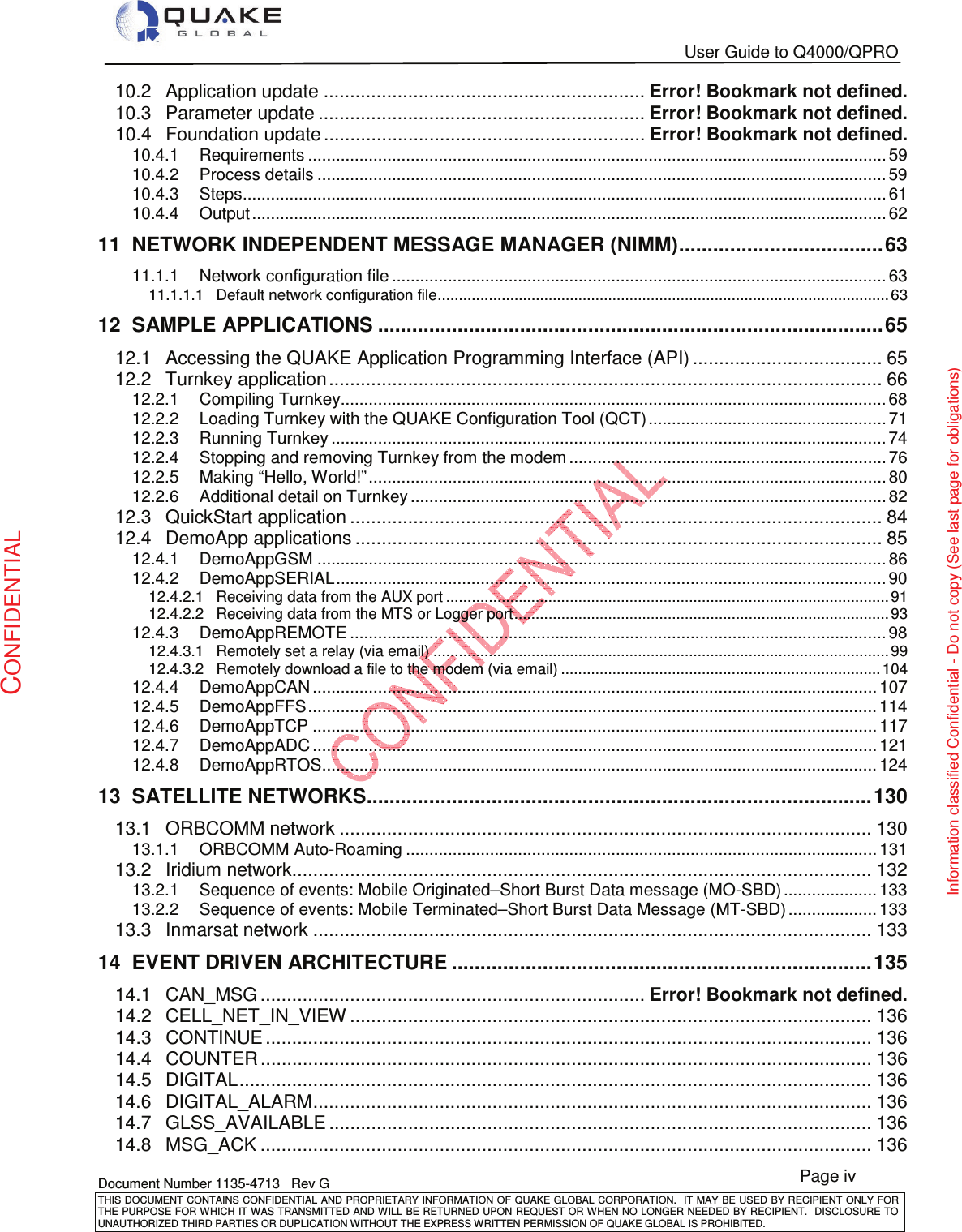
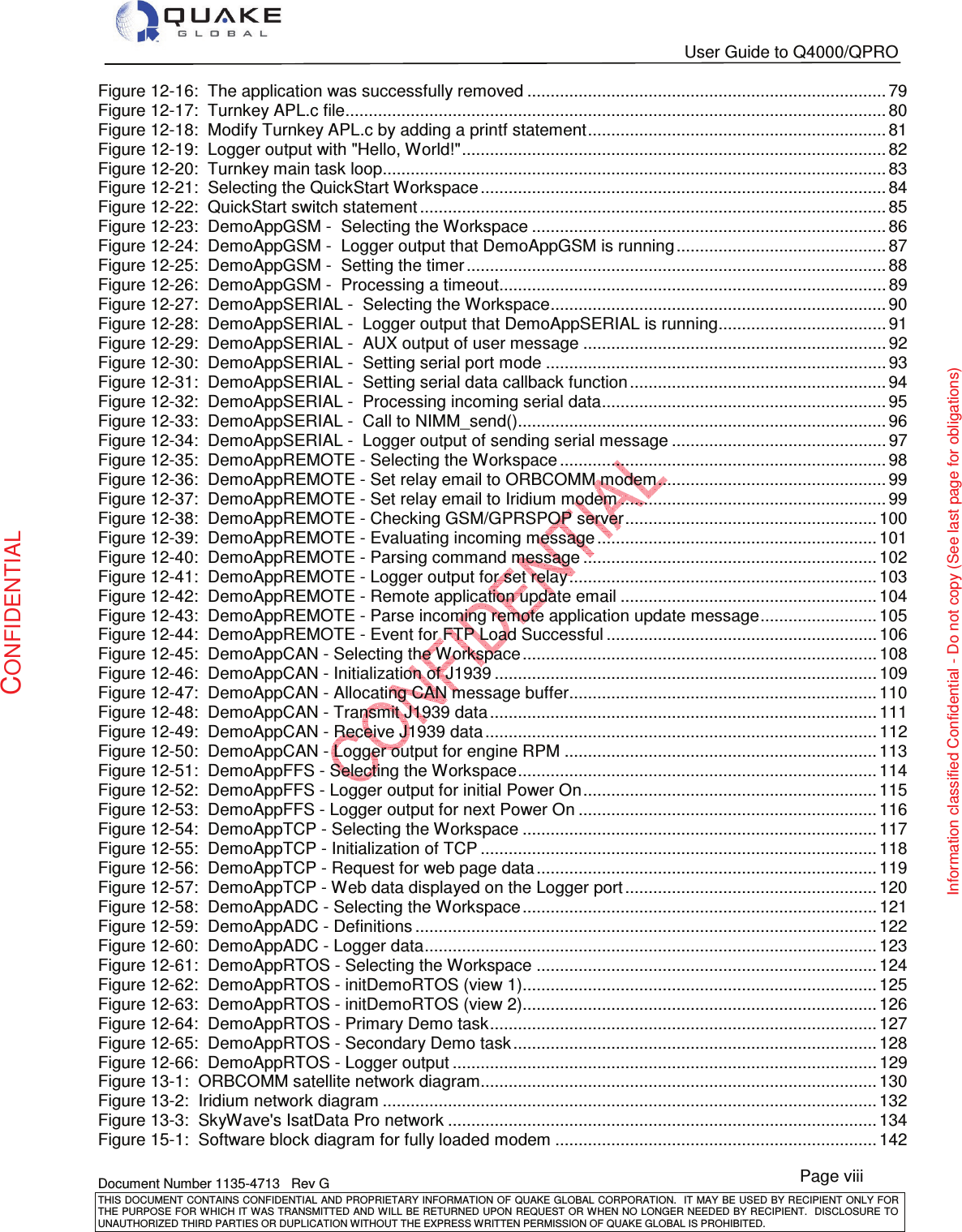
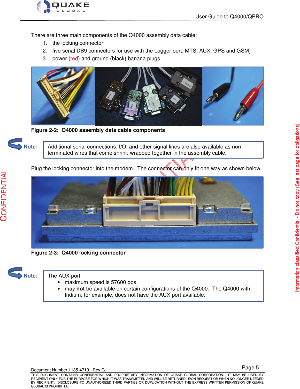
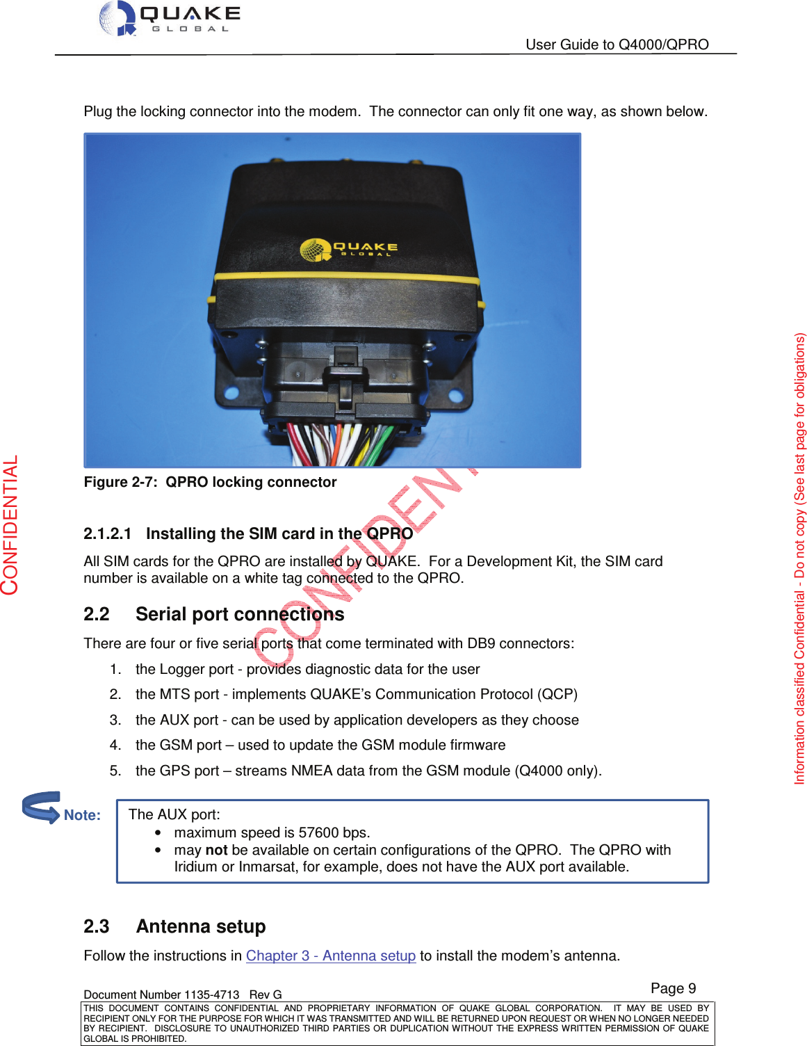
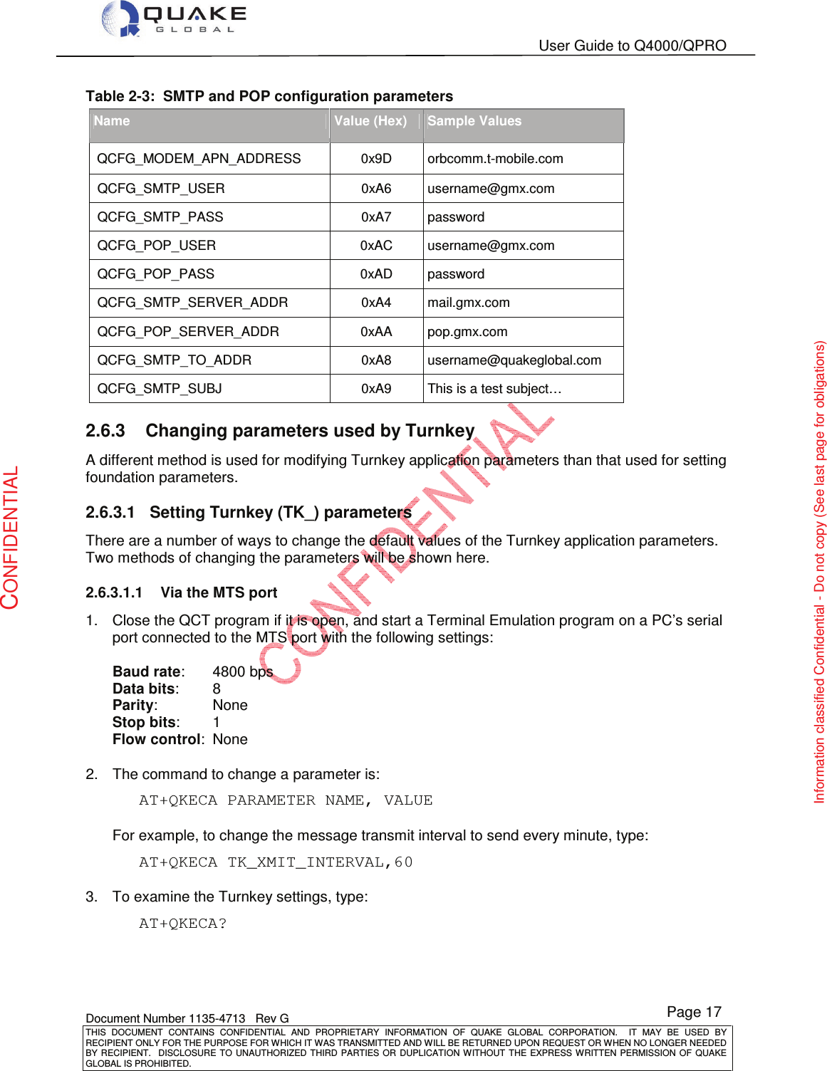
![User Guide to Q4000/QPRO Document Number 1135-4713 Rev G THIS DOCUMENT CONTAINS CONFIDENTIAL AND PROPRIETARY INFORMATION OF QUAKE GLOBAL CORPORATION. IT MAY BE USED BY RECIPIENT ONLY FOR THE PURPOSE FOR WHICH IT WAS TRANSMITTED AND WILL BE RETURNED UPON REQUEST OR WHEN NO LONGER NEEDED BY RECIPIENT. DISCLOSURE TO UNAUTHORIZED THIRD PARTIES OR DUPLICATION WITHOUT THE EXPRESS WRITTEN PERMISSION OF QUAKE GLOBAL IS PROHIBITED. Page 22 CONFIDENTIAL Information classified Confidential - Do not copy (See last page for obligations) 2.6.6 Turnkey Logger messages 2.6.6.1 Turnkey messages at boot up When the modem boots with the Turnkey application loaded, the current settings of the Turnkey parameters will be displayed on the Logger port. If SMTP and POP addresses are configured, they will be displayed also. This log information provides the dates and version numbers of the QUAKE Turnkey and foundation code, as well as the values for Turnkey parameters and SMTP and POP address information. Below is a sample log file: Copyright (C) 2010 QUAKE Global Inc. All rights reserved. This work is the copyrighted intellectual property of QUAKE Global Incorporated, and may not be copied, decompiled, modified,or distributed, in whole or in part, without the express written permission of the copyright holder. The copyright notice above does not evidence any actual or intended publication of such source code. Boot Loader Version 2.1 Built at 15:01:55 on Jun 9 2010 Verifying the image... Loading Version 1.3 of the QUAKE Foundation Noted: 3030.10065 Product: 1, Feature: a Starting the image CP Code version Mar 14 2011 11:03:38 Configuring RTC... SYS_setTime: Updated system time status (Src RTC Sync 0) Current Time: 14Mar11 00:00:00 This unpublished source file is the copyrighted intellectual property of QUAKE Global Incorporated, and may not be copied, decompiled, modified, or distributed, in whole or in part, without the express written permission of the copyright holder. The copyright notice above does not evidence any actual or intended publication of such source code. THIS PRODUCT IS COVERED BY THE FOLLOWING US PATENTS: 7,289,533. OTHER PATENTS PENDING. UTL_nvmProtectedRead: Updating /tffs0/BACKUP/CFGMGR.CM desired_gwy_id: 1 QUAKE Global SC #QWAKETEST029 TL Code version 1.12.1 No ETS_CHANNEL_MODES; default to elapsed times inactive. No SMH_WRITE_INTERVAL; default to 720 seconds. Reading 1 MSN LL elements from NVM MSN LL[0] Gwy 1 SCT: Msg 0 980167696 Gg 0 984084496 SCO: Msg 14 Gg 1 Rpt 1 Starting customer application](https://usermanual.wiki/Quake-Global/96XXCS.Full-Manual-part-1/User-Guide-1626632-Page-33.png)