Quake Global 96XXCS Q4000 / QPRO Satellite Module User Manual Datasheet Q4000
Quake Global Inc. Q4000 / QPRO Satellite Module Datasheet Q4000
UserManual.wiki
>
Quake Global
>
96XXCS User Manual
>
Datasheet Q4000
Contents
1.
Datasheet QPRO
2.
Full Manual part 2
3.
Full Manual part 3
4.
Full Manual part 5
5.
Full Manual part 7
6.
Datasheet Q4000
7.
Full Manual part 1
8.
Full Manual part 4
9.
Full Manual part 6
Datasheet Q4000
Navigation menu
Upload a User Manual
Namespaces
Wiki Guide
HTML
PDF
Info
Views
User Manual
Discussion / Help
Navigation


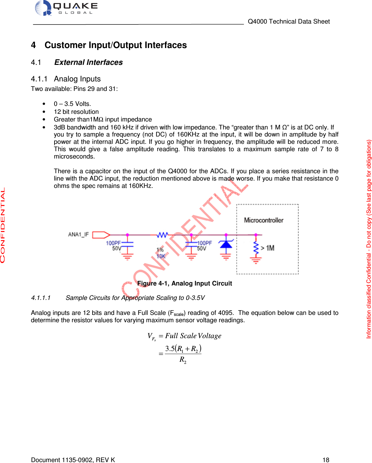

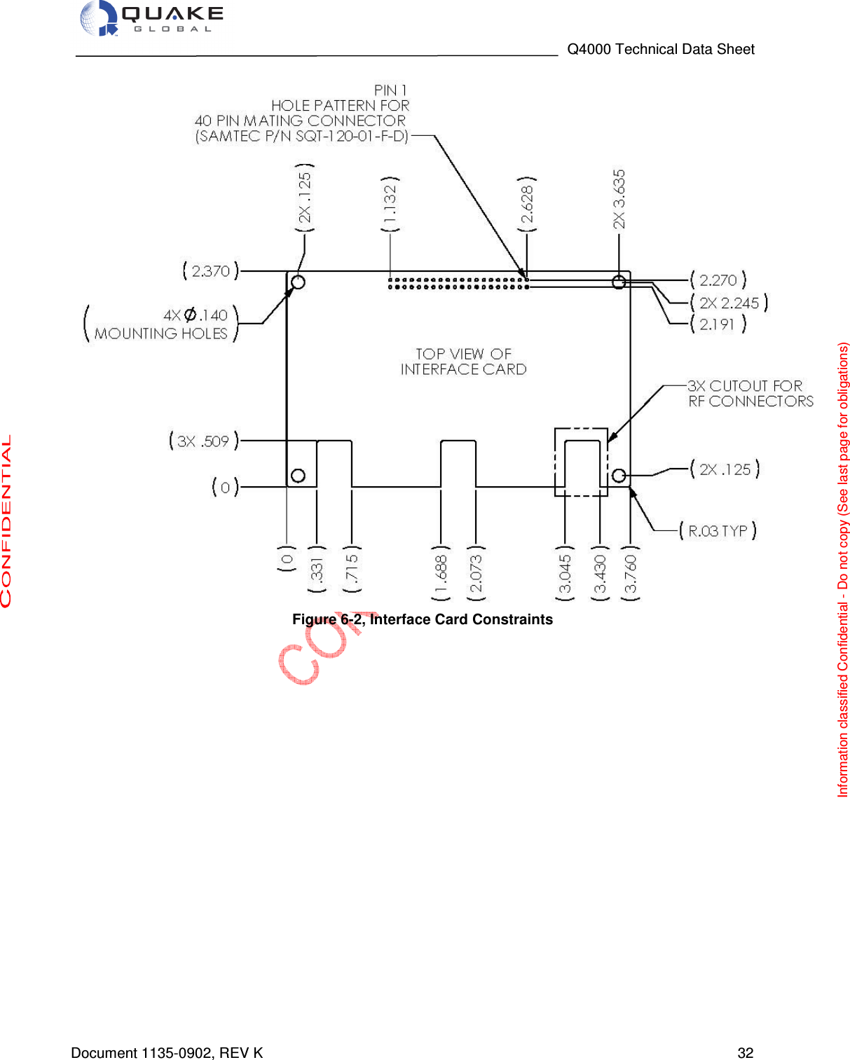
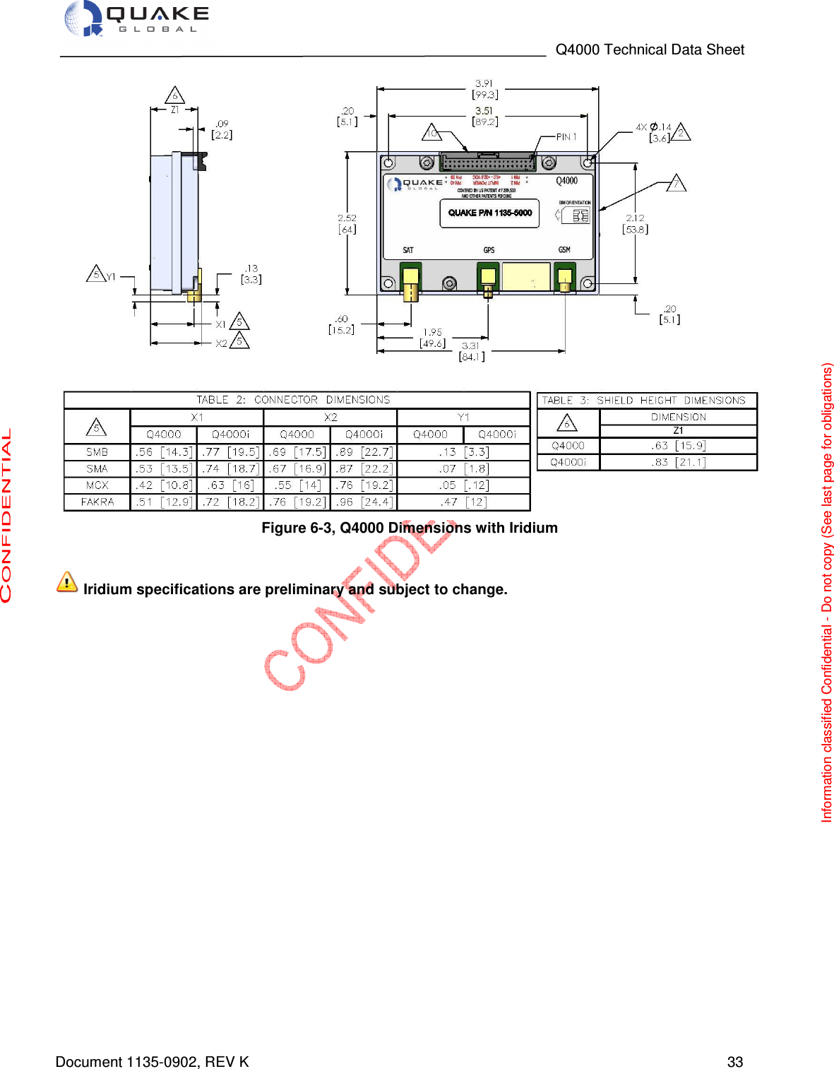
![Q4000 Technical Data Sheet Document 1135-0902, REV K 27 5 Q4000 Data Interface Specifications Data Interfaces 5.1· 4 Digital Controlled Output Switches (2 Switched GND/2 Switched Input Voltage) · 8 Digital General Purpose Inputs/Outputs (CMOS level 3.5VDC) · 3 Serial Ports (External) with up to 5 RS-232 serial ports depending on Q4000 configuration · 1 CAN BUS 2.0: J1850/1939 · 2 Analog Inputs (0 – 3.5 V) Environmental Considerations 5.2As an OEM product, the Q4000 is designed to be housed in a sealed enclosure or in an environmentally benign area, since it is not sealed against moisture ingress. • Operating Temperature o –40C to 85C • Storage Temperature o –40C to 85C. • Low Pressure o Up to 4 hours at 15000 ft elevation pressure • Humidity o Relative humidity range of 0% to 95% non-condensing at 65C o Humidity Test in Orbcomm Spec E25050102 REV D is per MIL SPEC 810E, Method 507.3 with test conditions. o Procedure I, Cycle 2 - Procedure 1 simulates natural environmental cycles and is conducted on test items which are open to a frequently ventilated environment. Cycle 2 sets the temperature at a 24C constant with humidity maintained at 95% minimum. The Test Duration is 15 Cycles (15 days). • Cyclic Humidity o Temperature/Cyclic Humidity Test is 5 days at -10C to 65C at 85% relative humidity • Thermal Shock o -40C to 85C (30 minutes at each temp, 10 cycles) • Shock o Mechanical shock of a 20G, sawtooth profile, over an 11 msec period. (Three positive and three negative shocks in each of three mutually perpendicular axes) o SAEJ1455 shock requirements and those in MIL-STD-810E [11]. • Vibration o 20 Hz to 2 KHz, 8 Grms vibration profile in each of three mutually perpendicular axes, 1 hour per axis, o 10 Hz to 150 HZ, 0.5 g square/Hz vibration profile in each of three mutually perpendicular axes, 1 hour per axis. o 10 Hz to 150 HZ, 0.05 g^2/Hz vibration, 16 hours on each of three orthogonal axis o 5 Hz to 20 Hz , 0.05 g^2/hz, and from 20 to 150 Hz, -3 dB/octave, 1 hour each axes o Vibration requirements in Orbcomm Rev D spec [10] and MIL-STD-810E [11] Information classified Confidential - Do not copy (See last page for obligations)](https://usermanual.wiki/Quake-Global/96XXCS.Datasheet-Q4000/User-Guide-1626630-Page-27.png)