Psion RA2020 WIRELESS GATEWAY User Manual 80440
Psion Inc WIRELESS GATEWAY 80440
UserManual.wiki
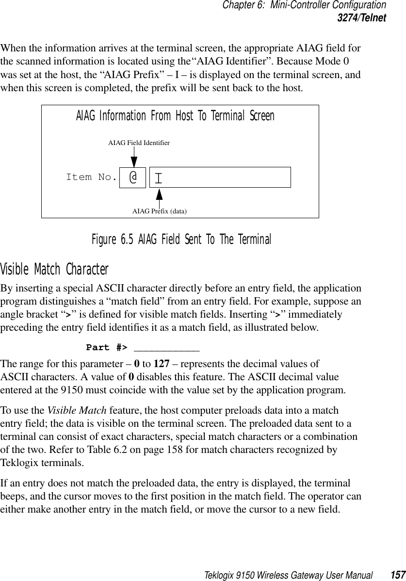
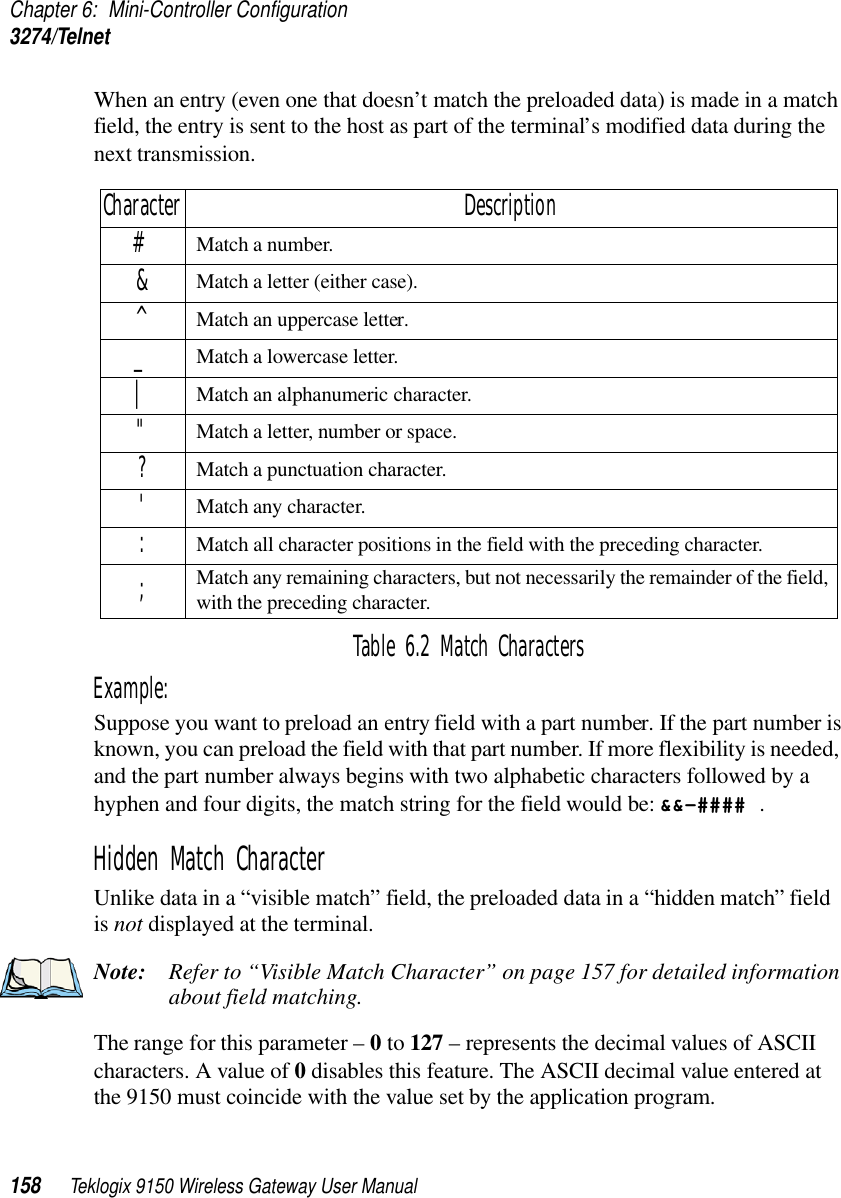
>
Psion
>
RA2020 User Manual
>
USERS MANUAL 3
Contents
1.
ANTENNA CO LOCATION WARNING
2.
FCC STATEMENT INFO TO USERS
3.
LETTER OF PHOTO
4.
USERS MANUAL 1
5.
USERS MANUAL 2
6.
USERS MANUAL 3
USERS MANUAL 3
Navigation menu
Upload a User Manual
Namespaces
Wiki Guide
HTML
PDF
Info
Views
User Manual
Discussion / Help
Navigation
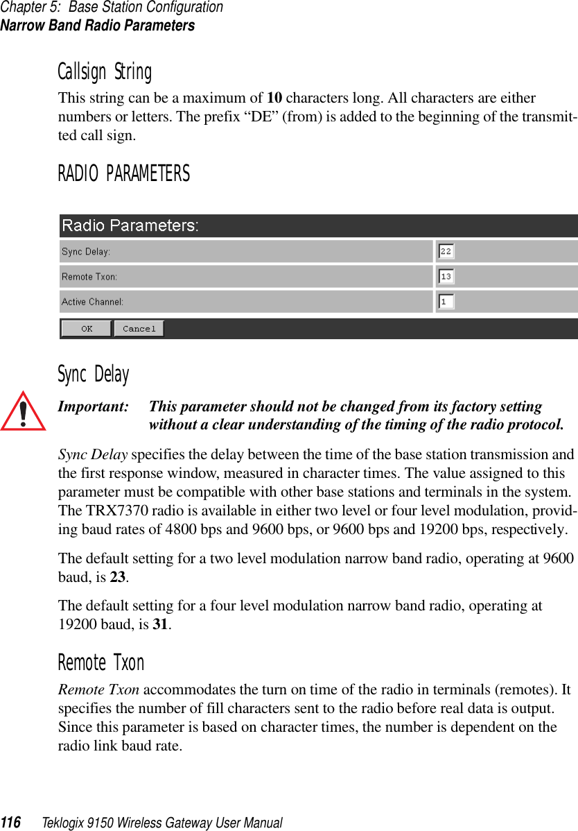
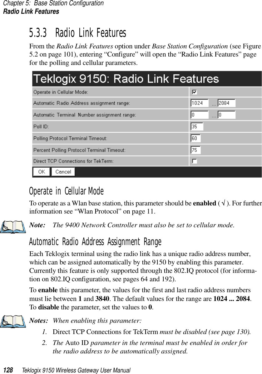
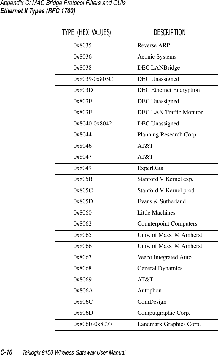
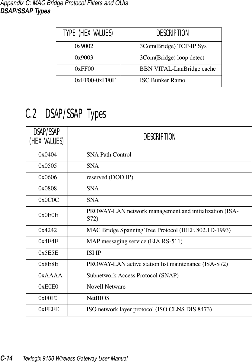
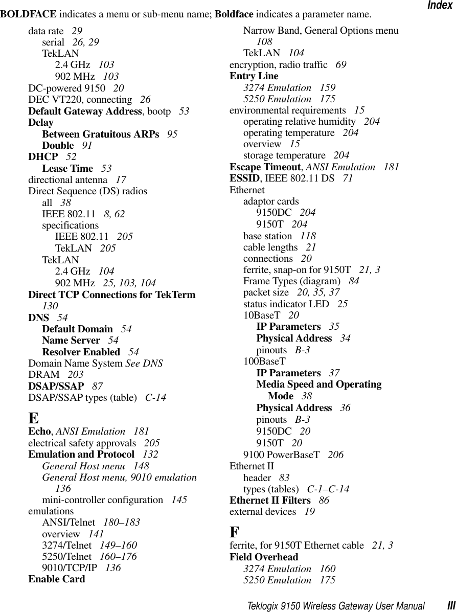
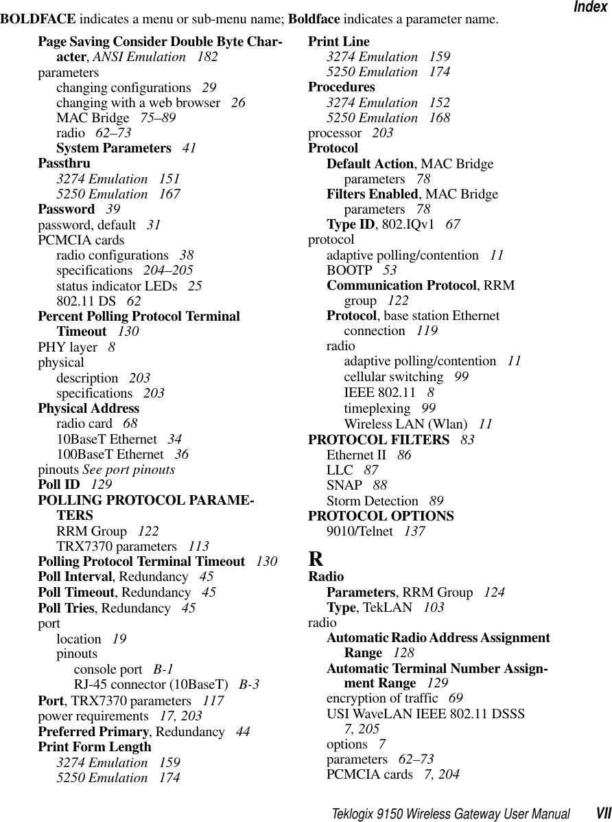
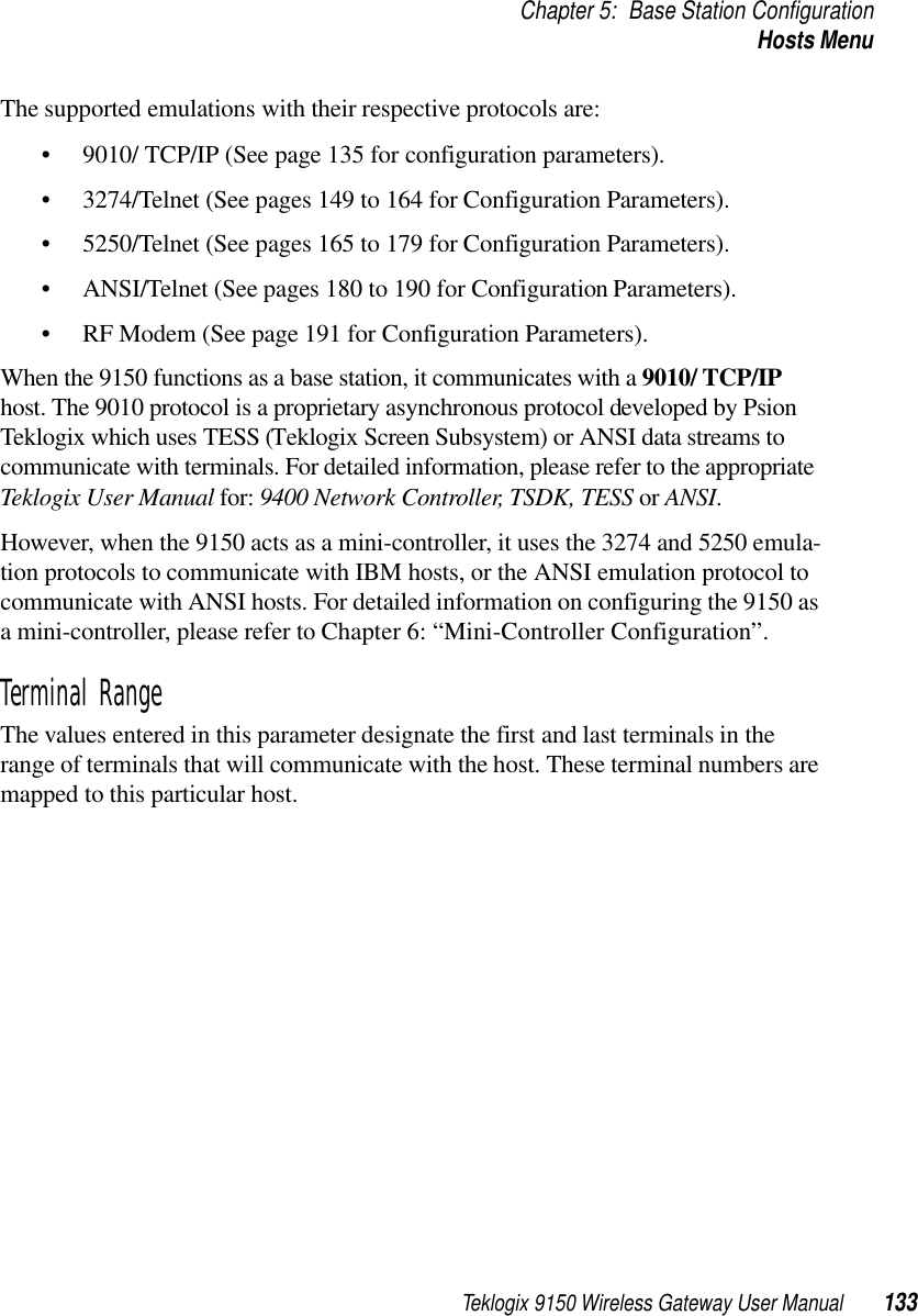
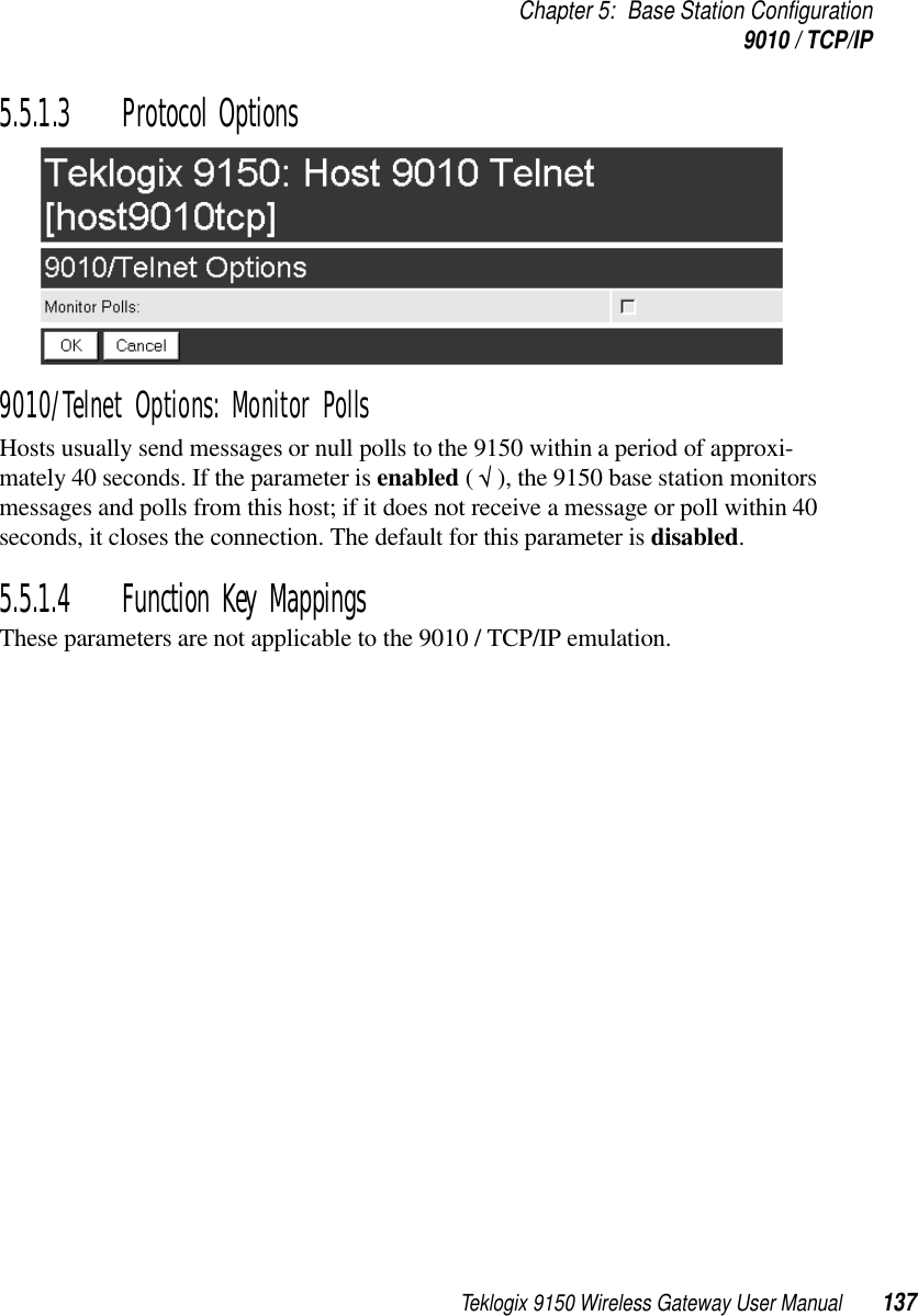
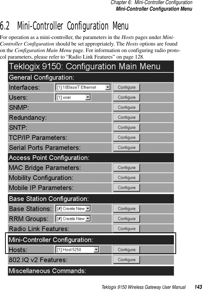
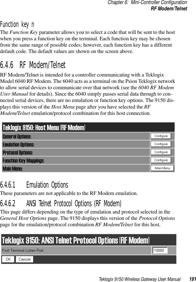
![Chapter 5: Base Station ConfigurationHosts Menu132 Teklogix 9150 Wireless Gateway User ManualOpening the “Configure” dialog box for a selected host lists the parameters that can be modified or deleted for that host. New hosts can be added by selecting “[#] Create New” in the drop-down menu before entering the “Configure” dialog box.NameThis parameter indicates the assigned host name. The host name also appears on the RF terminal when switching between hosts in a multiple-host environment.Note: The name must not contain space characters.EnabledThe Enabled option must be turned on ( √ ) for terminals to communicate with this host.Emulation and ProtocolThis drop-down menu provides a list of host emulations and communication protocols supported by the 9150. Protocols are the methods by which terminals communicate with host computers over various physical media such as Ethernet and radio-link connections.](https://usermanual.wiki/Psion/RA2020.USERS-MANUAL-3/User-Guide-400312-Page-17.png)
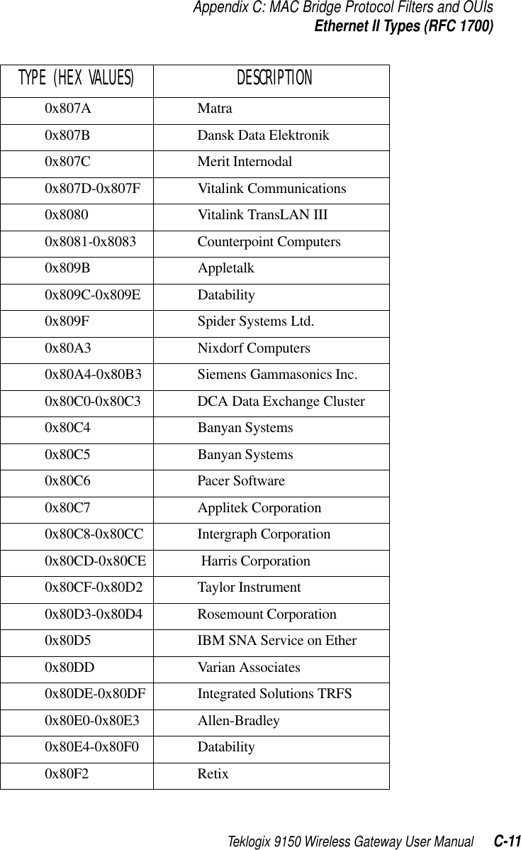
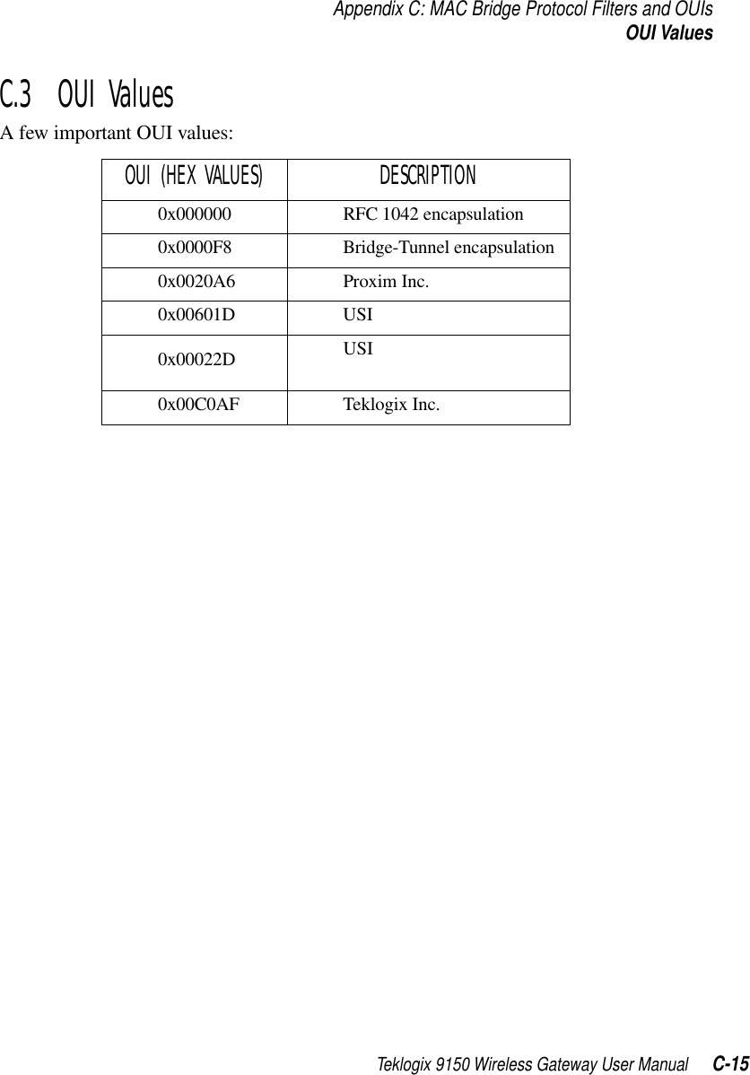
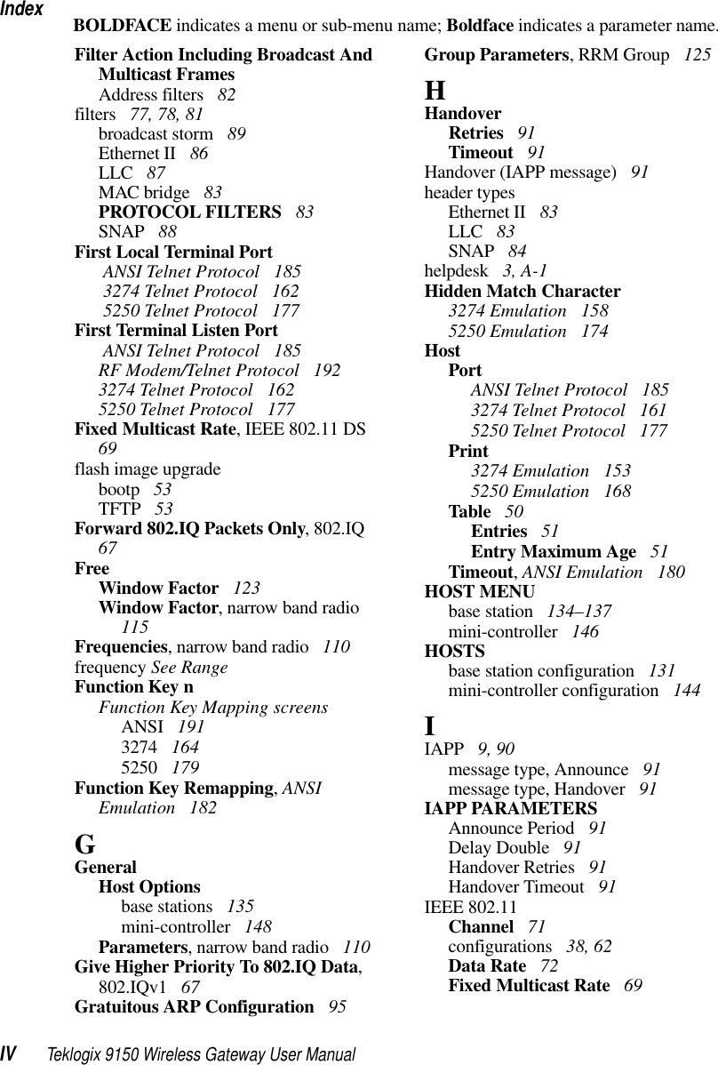
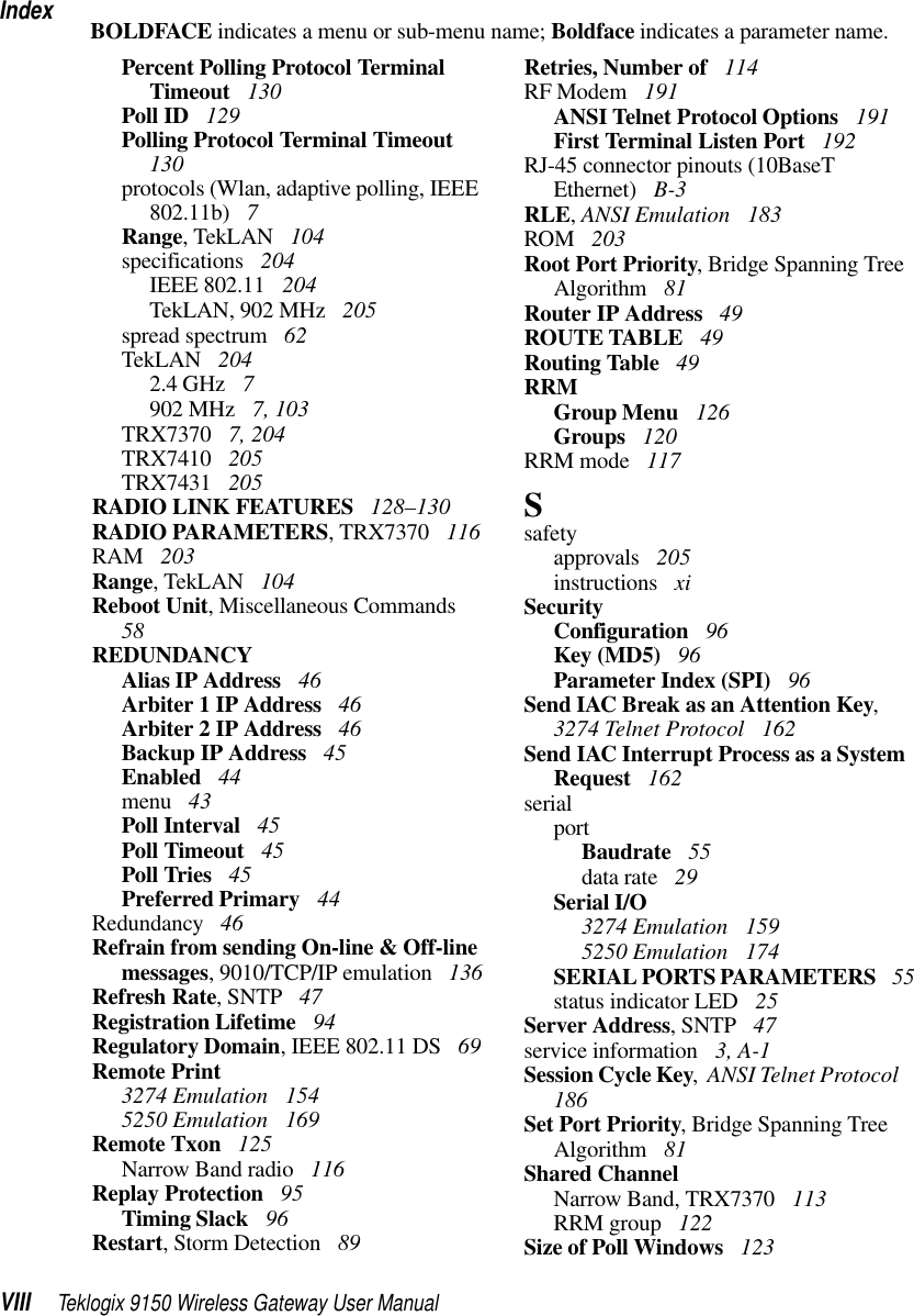
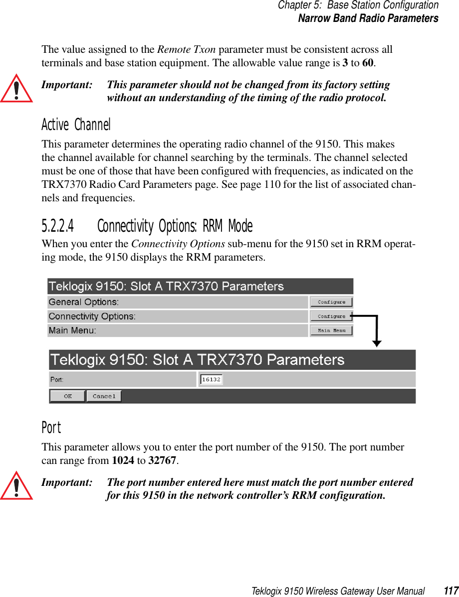
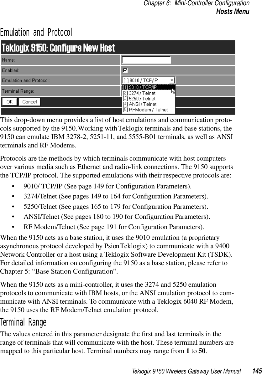
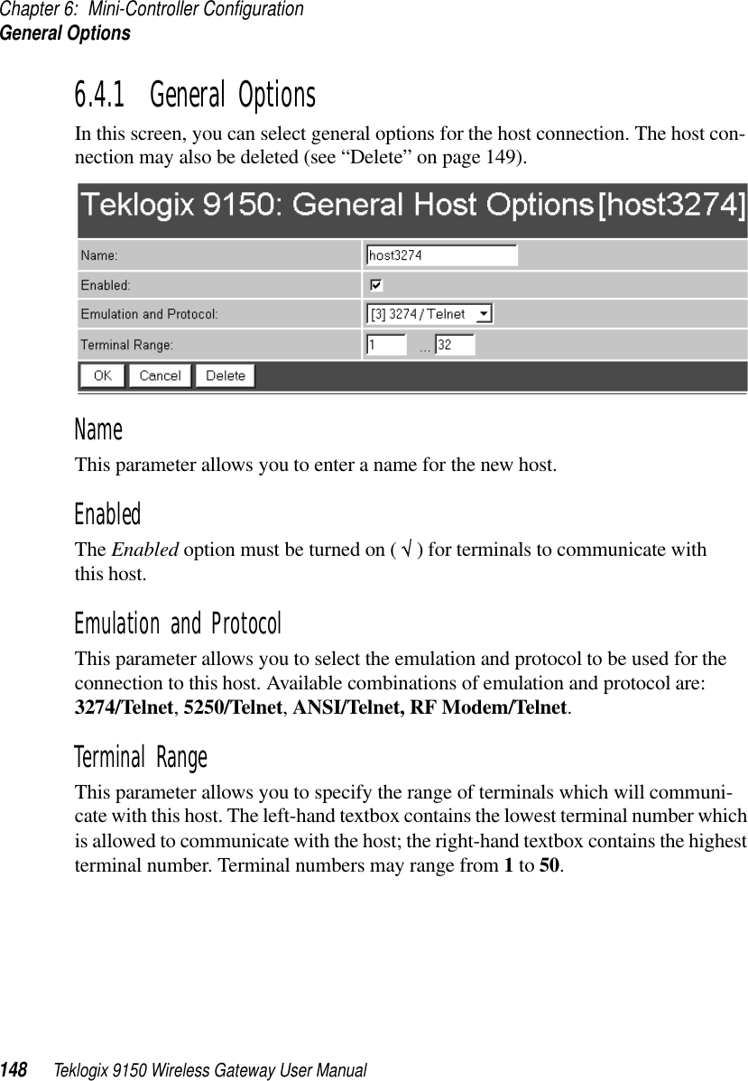
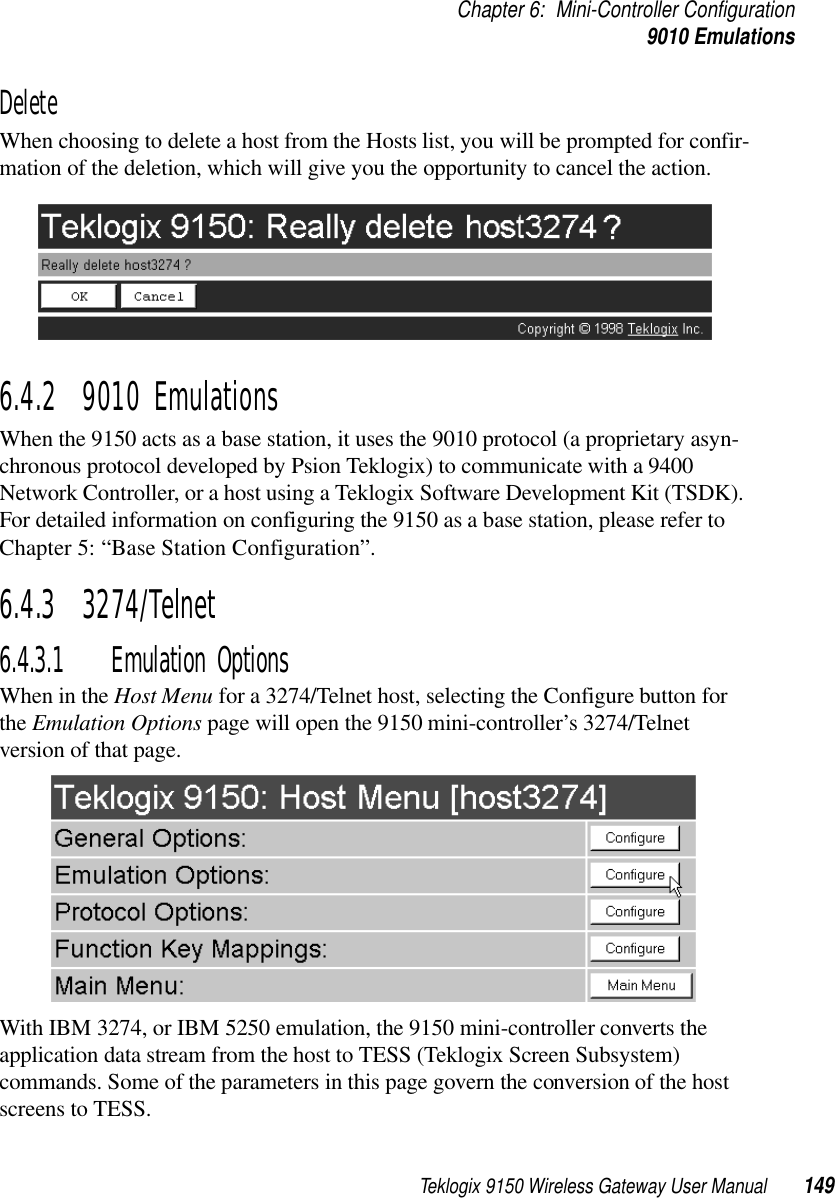
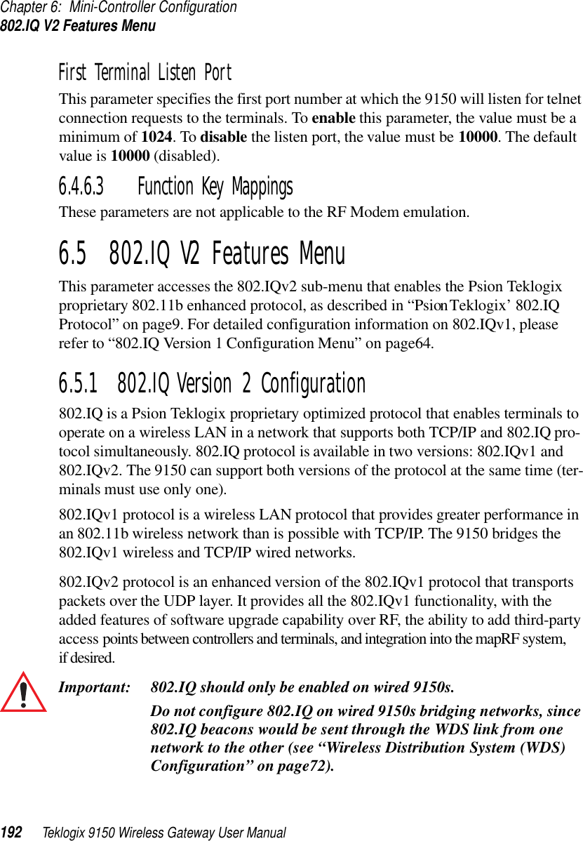
![Chapter 6: Mini-Controller ConfigurationHosts Menu144 Teklogix 9150 Wireless Gateway User Manual6.3 Hosts MenuThe drop-down menu in this option shows the host names present on the system. Up to six hosts can be supported. A “host” must be configured for each host that com-municates with the 9150 mini-controller. Opening the Configure dialog box for a selected host lists the parameters that can be modified or deleted for that host. New hosts can be added by selecting “[#] Create New” in the drop-down menu before entering the Configure dialog box.NameThis parameter indicates the assigned host name. The host name also appears on the RF terminal when switching between hosts in a multiple-host environment.EnabledThe Enabled option must be turned on ( √ ) for terminals to communicate with this host.](https://usermanual.wiki/Psion/RA2020.USERS-MANUAL-3/User-Guide-400312-Page-29.png)
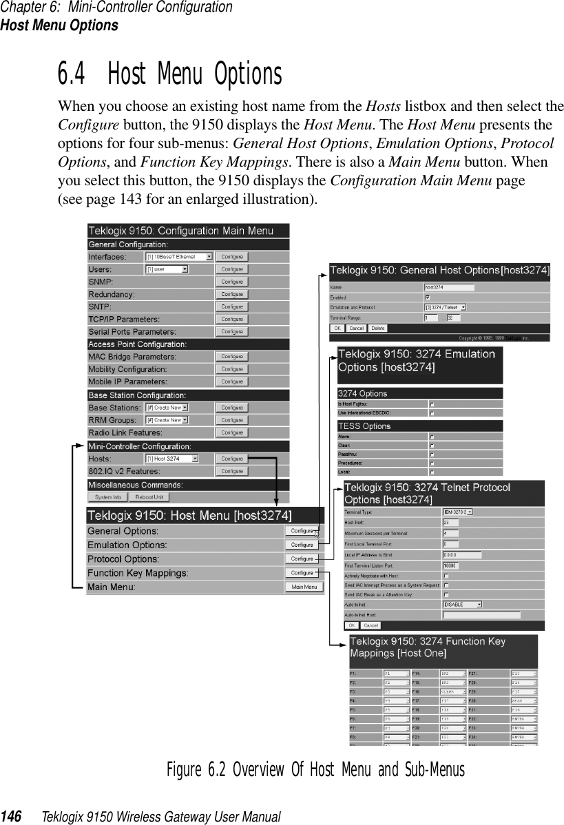
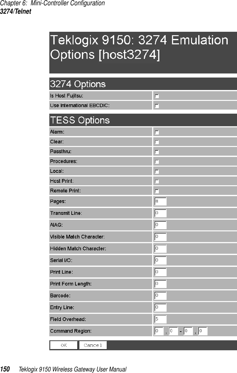
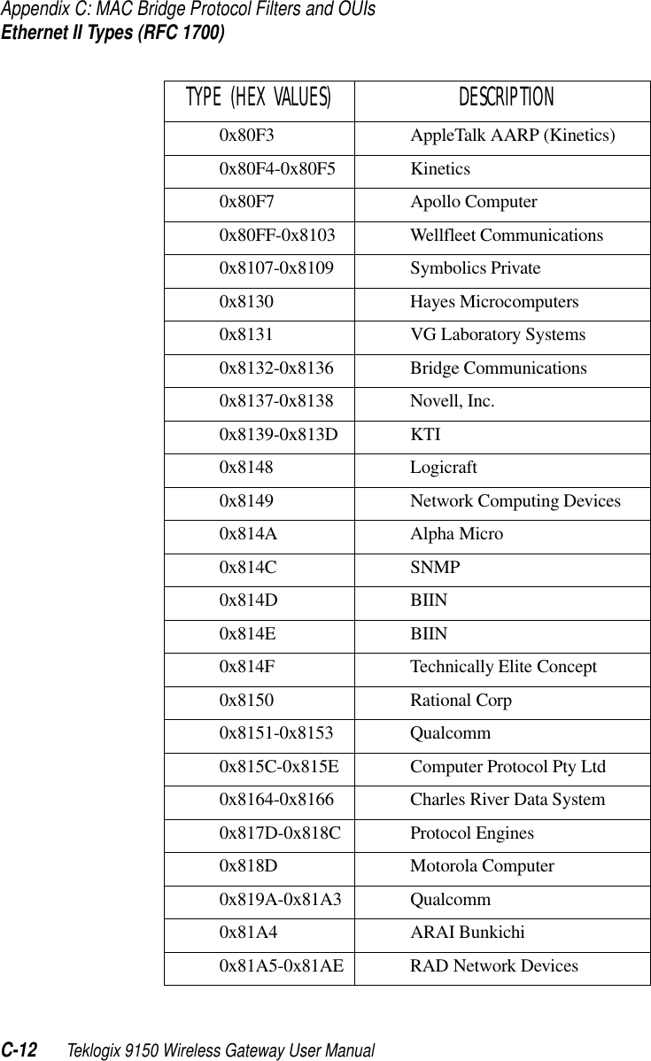
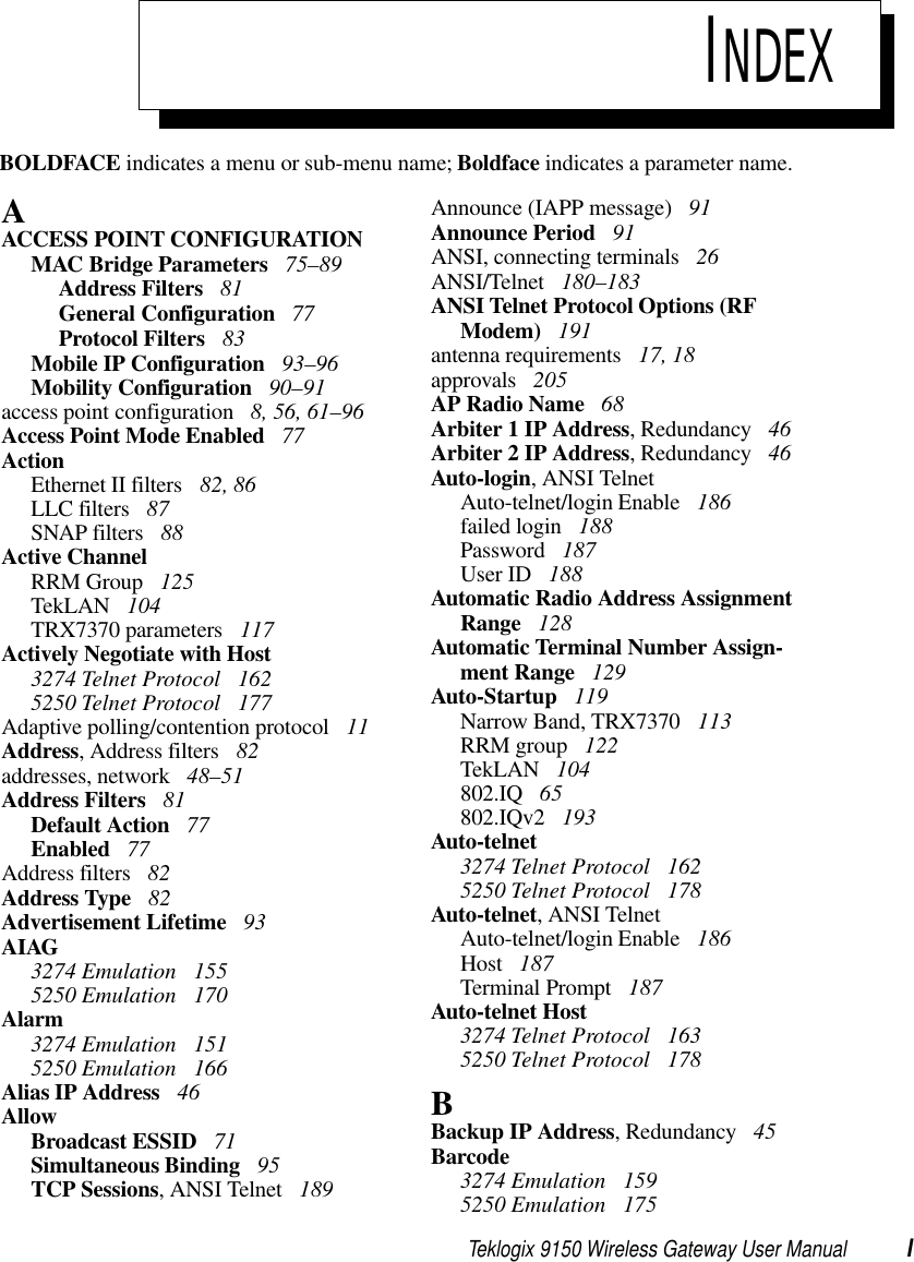
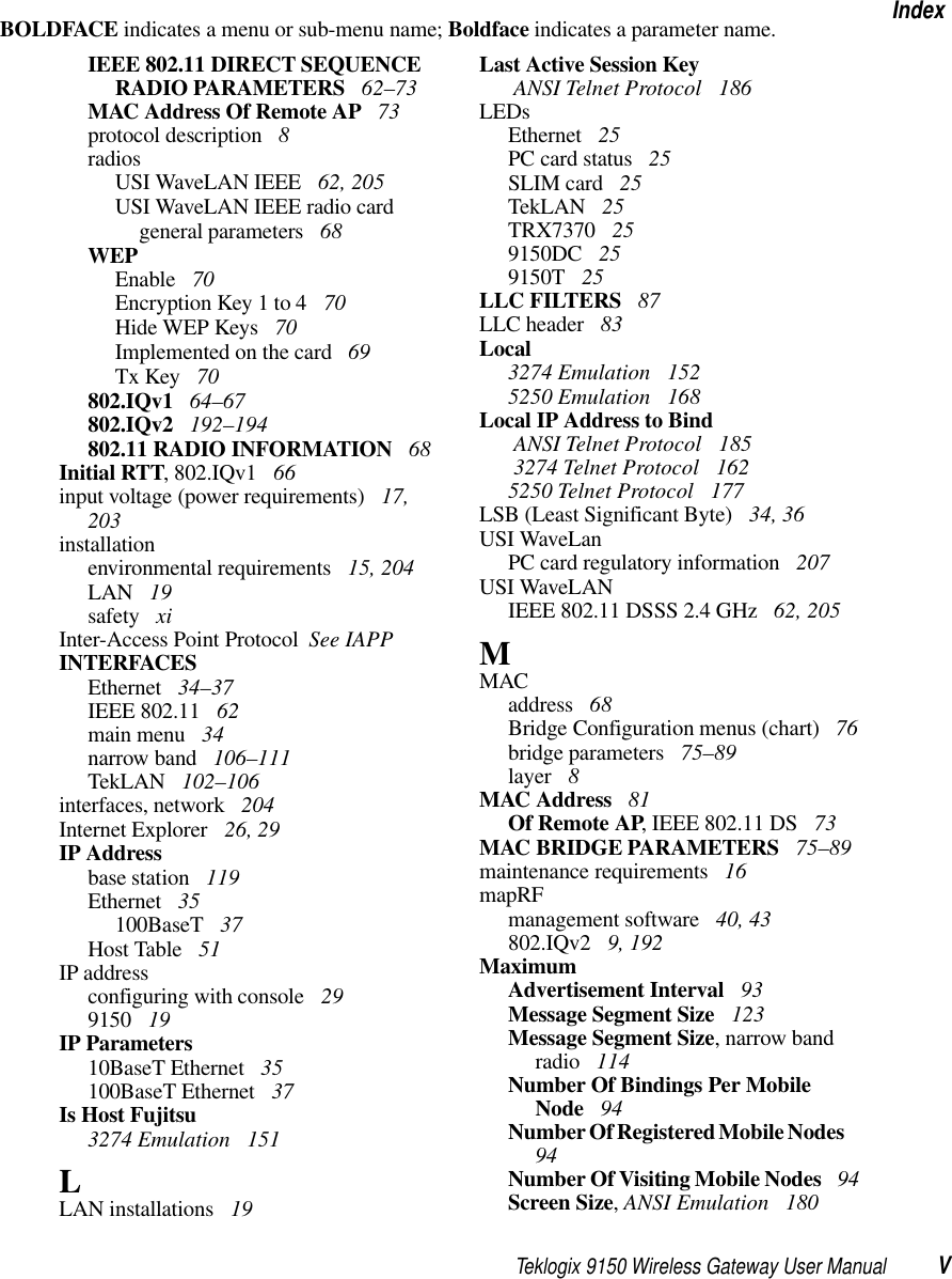
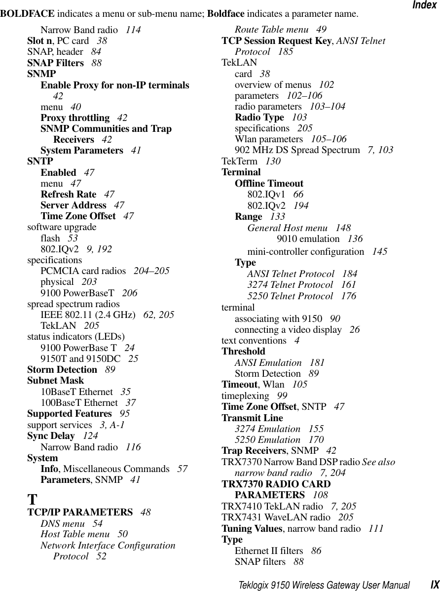
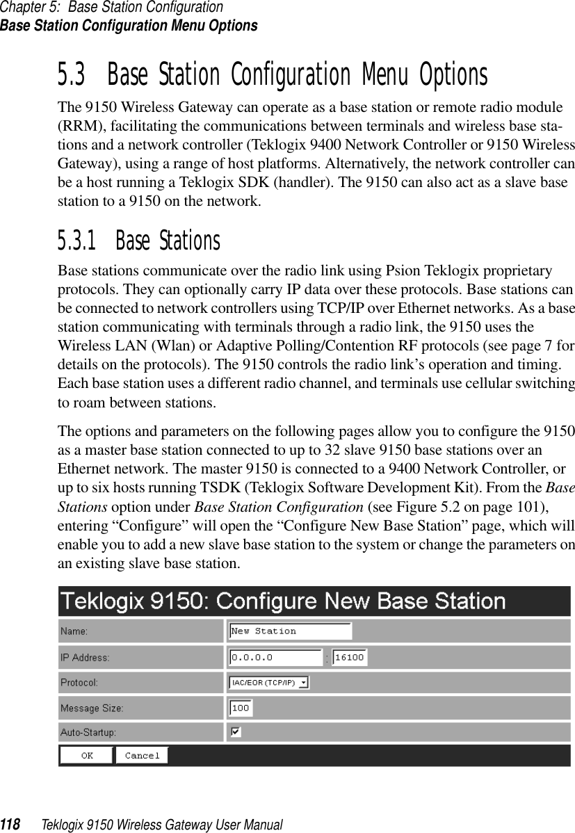
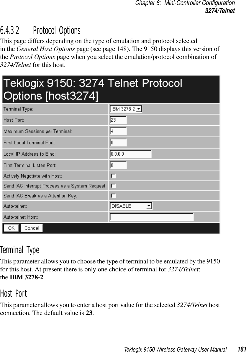
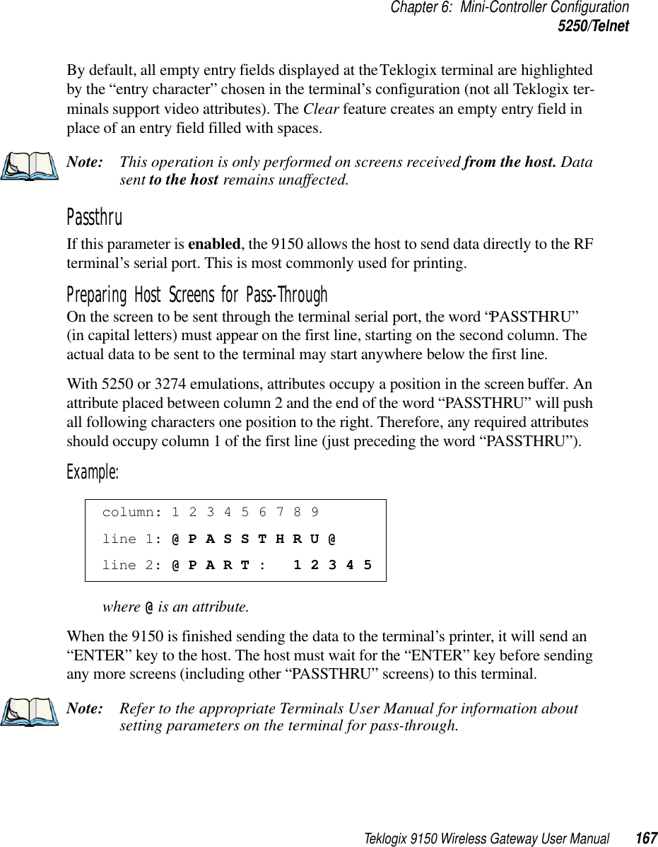
![Teklogix 9150 Wireless Gateway User Manual 151Chapter 6: Mini-Controller Configuration3274/TelnetIs Host Fujitsu If this parameter is enabled, the 9150 mini-controller expects the data from the host to contain commands, etc., native to a Fujitsu host. Enabling this parameter causes the standard IBM formatting codes (for start of field, setting buffers, etc.) to be replaced by the codes used by Fujitsu host computers.Use International EBCDIC If this parameter is enabled, the 9150 mini-controller uses the International EBCDIC character set, swapping the positions of the ! and ] characters. Alarm When this parameter is enabled, terminals beep when the word “ALARM” appears on the application screen in the location specified by the Command Region parame-ter (see page 160). The word “ALARM” should be a display-only field.Note: The Command Region parameter must be enabled for this parameter to work.Clear If this parameter is enabled, the 9150 mini-controller creates an empty entry field for an entry field that is filled with spaces.Some host applications rely on the video attributes of displayed characters to high-light fields, particularly entry fields. For example, the application screen may define all entry fields with reverse video and fill the field with spaces. This is effective on terminals that support reverse video, but on terminals that do not, it can make the field invisible since it is made up entirely of spaces.By default, all empty entry fields displayed at the Teklogix terminal are highlighted by the “entry character” chosen in the terminal’s configuration (not all Teklogix ter-minals support video attributes). Note: This operation is only performed on screens received from the host. Data sent to the host remains unaffected.Passthru If this parameter is enabled, the 9150 allows the host to send data directly to the RF terminal’s serial port. This is most commonly used for printing.](https://usermanual.wiki/Psion/RA2020.USERS-MANUAL-3/User-Guide-400312-Page-36.png)
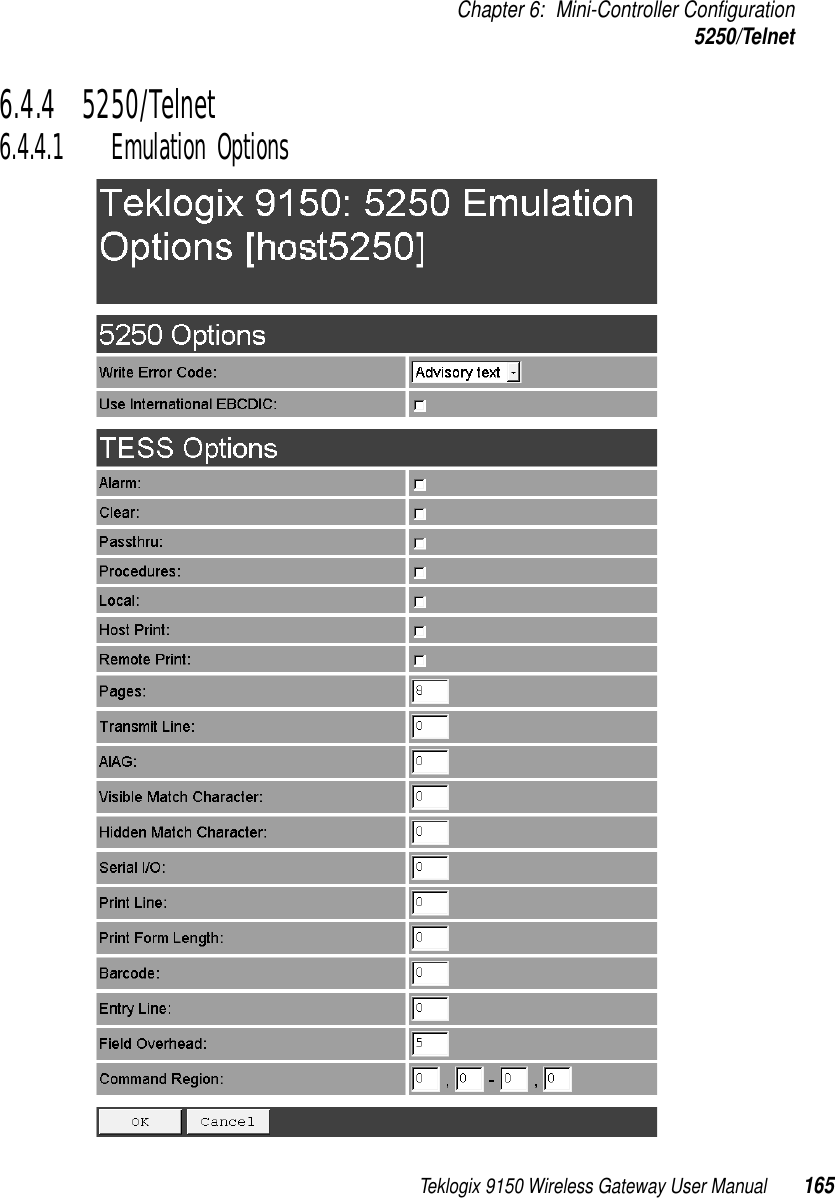
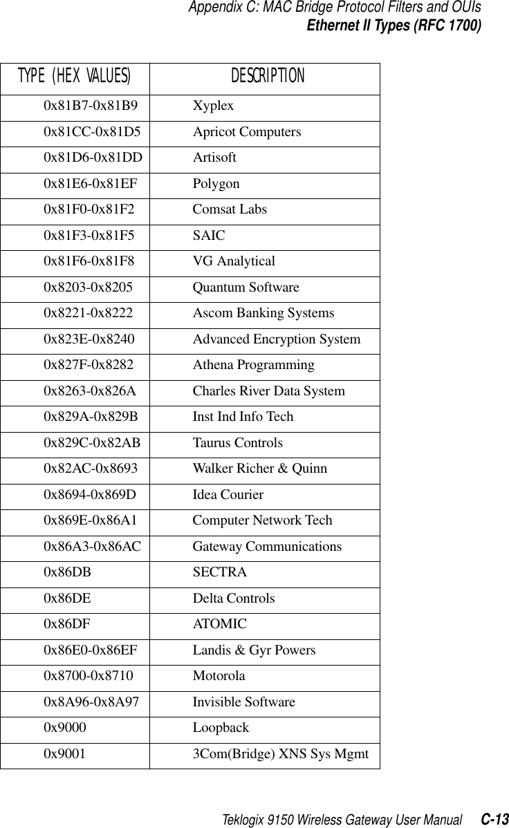
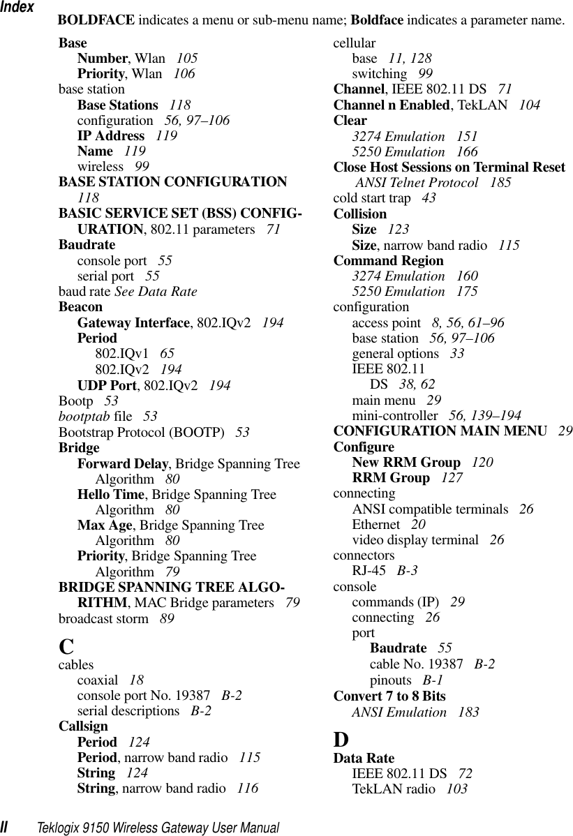
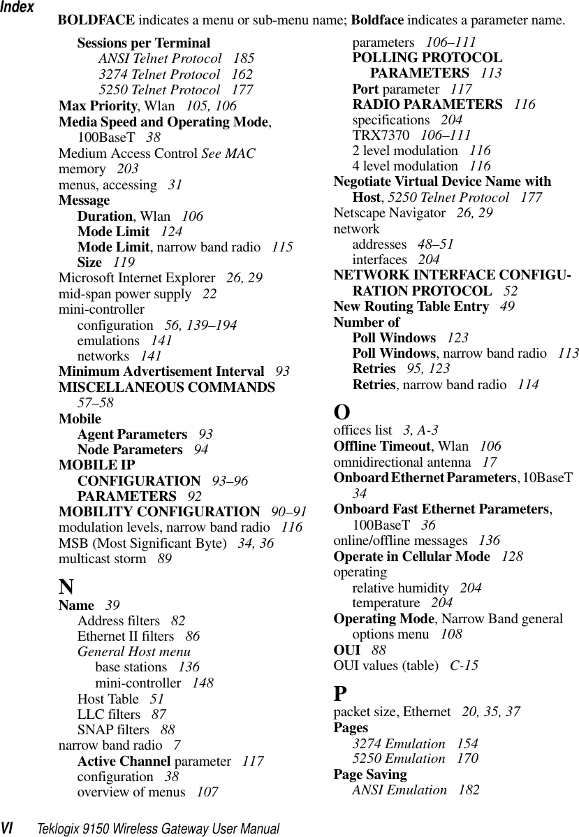
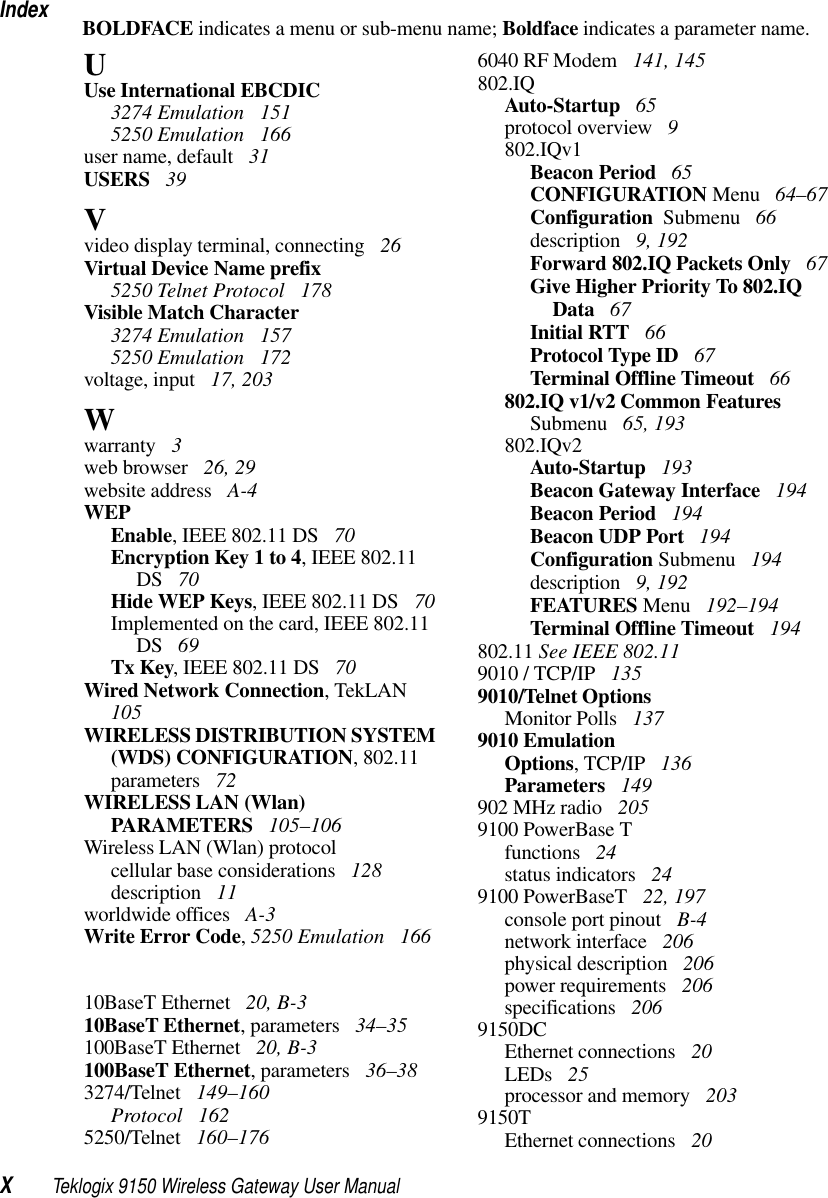
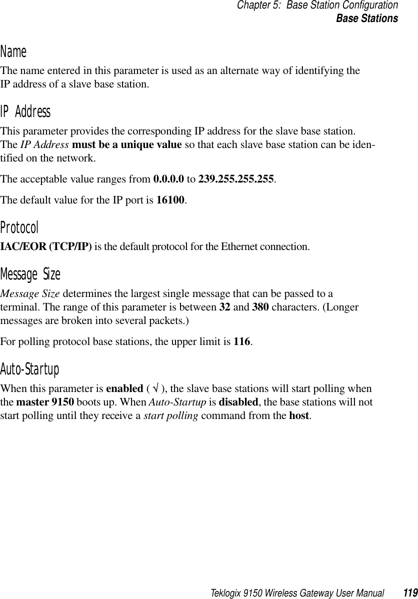
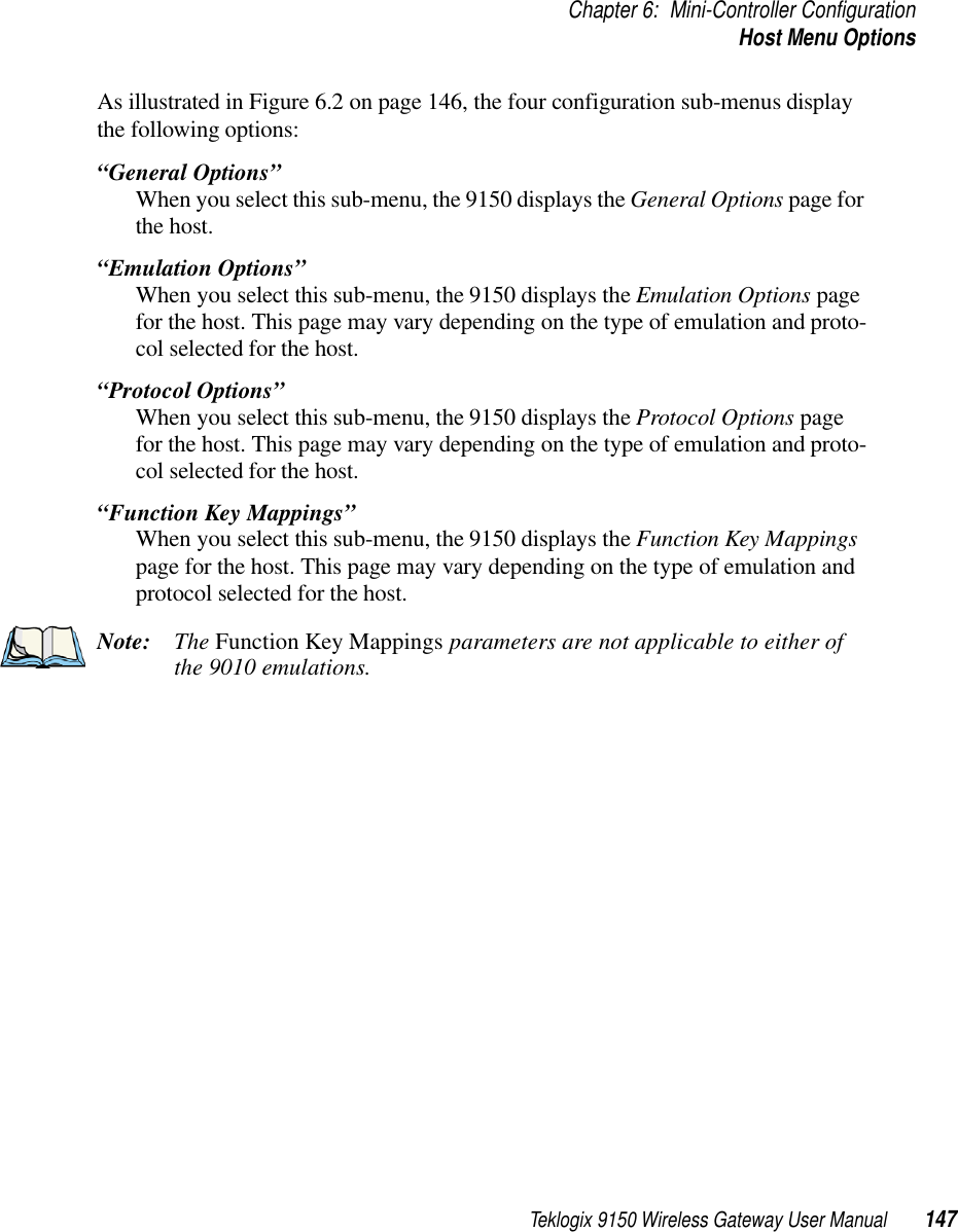
![Chapter 6: Mini-Controller Configuration5250/Telnet166 Teklogix 9150 Wireless Gateway User ManualThe 9150 displays this version of the Emulation Options page after you have selected the 5250/Telnet emulation/protocol combination for this host connection.With IBM 5250, or IBM 3274 emulation, the 9150 mini-controller converts the application data stream from the host to TESS (Teklogix Screen Subsystem) commands. Some of the parameters in this page govern the conversion of the host screens to TESS.Write Error Code If advisory text is selected here, the 9150 sends error codes to the terminal screen as advisory text, which is written at the bottom of the screen. If screen text is chosen, the 9150 sends the error codes as regular screen text.Use International EBCDIC If this parameter is enabled, the 9150 will swap the positions of the ! and ] charac-ters in the EBCDIC character table.Alarm If this parameter is enabled, terminals will beep when the word “ALARM” (in capital letters) appears on the application screen, in the location specified by the Command Region parameter (see page 175). The word “ALARM” should be a display-only field.Note: The Command Region parameter must be enabled for this parameter to work.Clear If this parameter is enabled, the 9150 mini-controller creates an empty entry field for an entry field that is filled with spaces.Some host applications rely on the video attributes of displayed characters to high-light fields, particularly entry fields. For example, the application screen may define all entry fields with reverse video and fill the field with spaces. This is effective on terminals that support reverse video, but on terminals that do not, it can make the field invisible since it is made up entirely of spaces.](https://usermanual.wiki/Psion/RA2020.USERS-MANUAL-3/User-Guide-400312-Page-51.png)
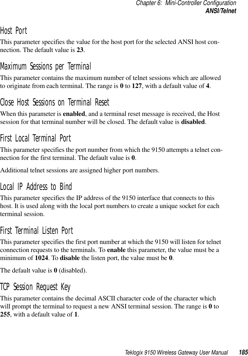
![Teklogix 9150 Wireless Gateway User Manual 189Chapter 6: Mini-Controller ConfigurationANSI/TelnetAllow TCP SessionsWhen this parameter is enabled, the 9150 allows a terminal user to switch prompts or sessions while at the prompt (either Auto-login or TCP). If Allow TCP Sessions is disabled, all new sessions will open as Auto-login sessions. Requesting sessions (normally <CTRL> a on the terminal) can be used at the prompt level to change the type of prompt (if the other type of prompt is available). Switching sessions at the prompt level is also available (on the terminal as <CTRL> b [next session], or <CTRL> e [last session]). When switching sessions at the prompt, the terminal state (not logged in) will be correctly adjusted to match that of the switching in session. The default value is enabled.](https://usermanual.wiki/Psion/RA2020.USERS-MANUAL-3/User-Guide-400312-Page-74.png)
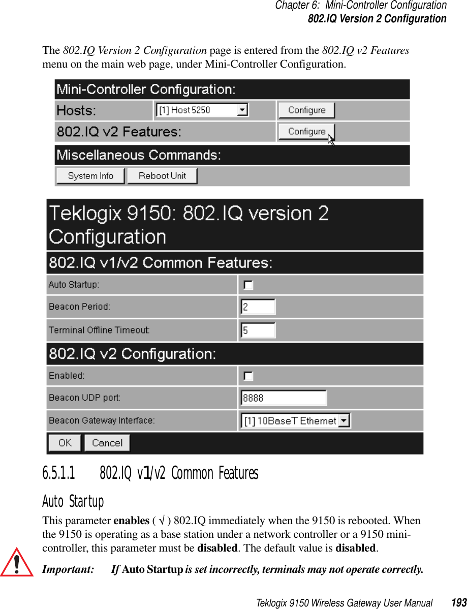
![Chapter 6: Mini-Controller Configuration802.IQ Version 2 Configuration194 Teklogix 9150 Wireless Gateway User ManualBeacon PeriodAn 802.IQ beacon is a broadcast sent out to all 802.IQ-enabled terminals. The beacon allows terminals to determine when they have roamed between base stations. It enables a terminal to determine whether or not the base station or controller was rebooted and, if so, how to recover. If the controller was rebooted, the terminal closes all sessions and fully re-initializes. If the base station was rebooted, or if the terminal moved to a different 9150, a warm initialize is done (no data will be lost).The Beacon Period parameter acceptable value ranges from 1 to 20 seconds. The default value is 2.Terminal Offline TimeoutThis parameter sets the time (in minutes) before the 802.IQ task on the 9150 will send an offline message to the cellular master declaring the terminal offline. The acceptable value ranges from 1 to 240. The default value is 5.6.5.1.2 802.IQ v2 Configuration SubmenuEnabledThis parameter enables ( √ ) or disables the 802.IQv2 protocol. The default value is disabled.Beacon UDP PortThis parameter identifies the UDP port for beacon broadcasts. If more than one 802.IQv2 controller is on the network, the parameter must be changed to separate the systems. The parameter must also match the corresponding parameter on the ter-minal. The range of values is 5001 to 65535. The default value is 8888. Beacon Gateway InterfaceThis is the interface on which the beacons are sent out. The default is [1] 10BaseT Ethernet.](https://usermanual.wiki/Psion/RA2020.USERS-MANUAL-3/User-Guide-400312-Page-79.png)