Psion 8516 8516 Vehicle Mount Computer User Manual 8516 Vehicle Mount Computer
Psion Inc 8516 Vehicle Mount Computer 8516 Vehicle Mount Computer
UserManual.wiki
>
Psion
>
8516 User Manual
>
User Manual 3
Contents
1.
User Manual 1
2.
User Manual 2
3.
User Manual 3
User Manual 3
Navigation menu
Upload a User Manual
Namespaces
Wiki Guide
HTML
PDF
Info
Views
User Manual
Discussion / Help
Navigation
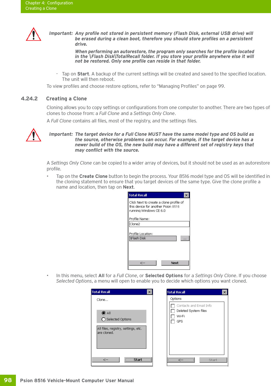
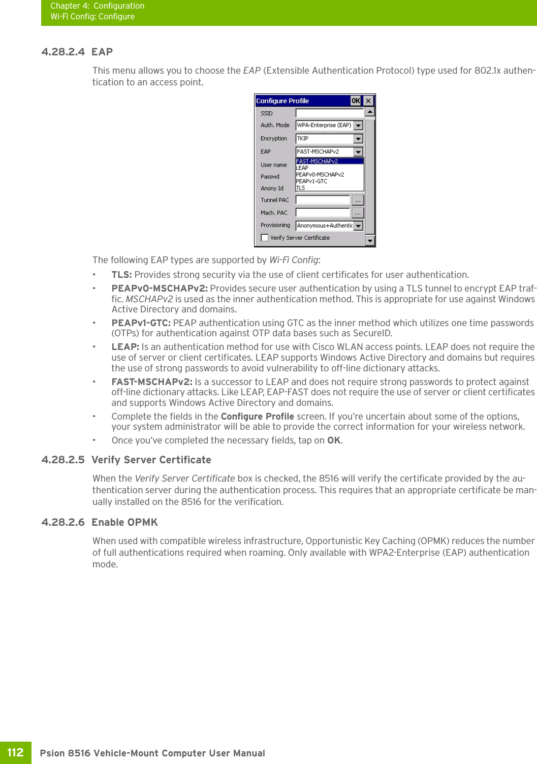
![Chapter 4: ConfigurationTotal Recall97 Psion 8516 Vehicle-Mount Computer User Manual4.24 Total RecallTotal Recall is a Psion utility developed to maintain applications and settings during a cold boot, as well as clone settings to other devices. This utility creates a restore point of a device at a known state. This can be used as a backup of the device (the administrator can clean the terminal and restore the profile at any time), or a clone (the administrator can store different configurations for different uses to clone to other Vehicle-Mount computers). •In the Control Panel, choose the Total Recall icon.In the startup up screen, you can choose from four options: Create Backup, Create Clone, Manage Profile, and Delete Profile.4.24.1 Creating a Backup•Tap on the Create Backup button to begin the process.This dialog box displays the Profile Name and the storage destination for the profile file.•In the Profile Name field, type a name for a profile. • If you want to choose another location for your backup file (optional), tap on the [...] button to the right of the Profile Location field and choose one of a number of folders. Note: Total Recall works differently (e.g. restore on cold boot or on clean boot) on different OS platforms and versions (e.g. Windows CE 5.0, 6.0, Windows Mobile, Windows Embedded Vehi-cle-Mount). For detailed information and other updates on Total Recall information, please go to the Ingenuity Working website at:http://community.psion.com/knowledge/w/knowledgebase/total-recall.aspx](https://usermanual.wiki/Psion/8516.User-Manual-3/User-Guide-1876108-Page-8.png)
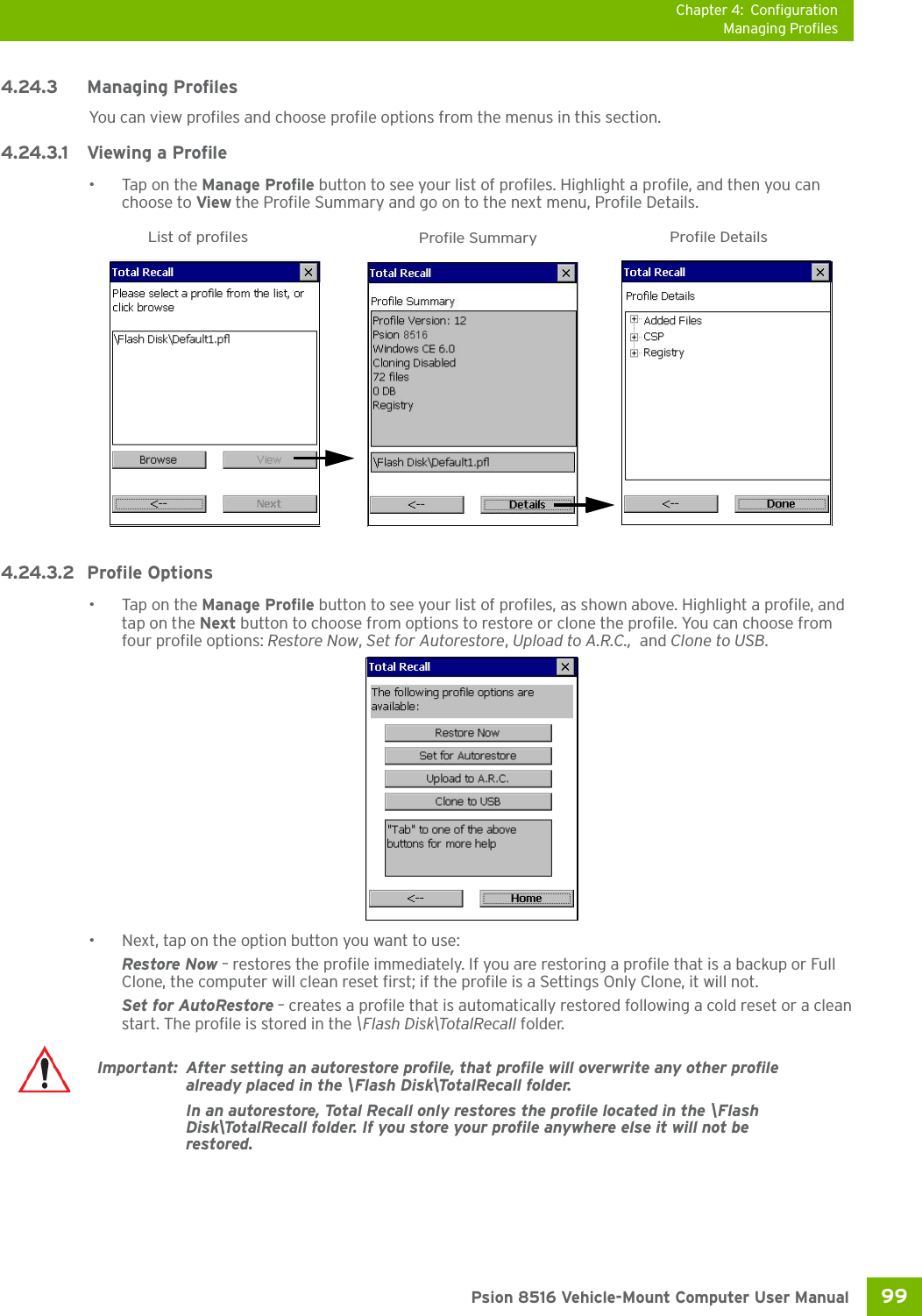
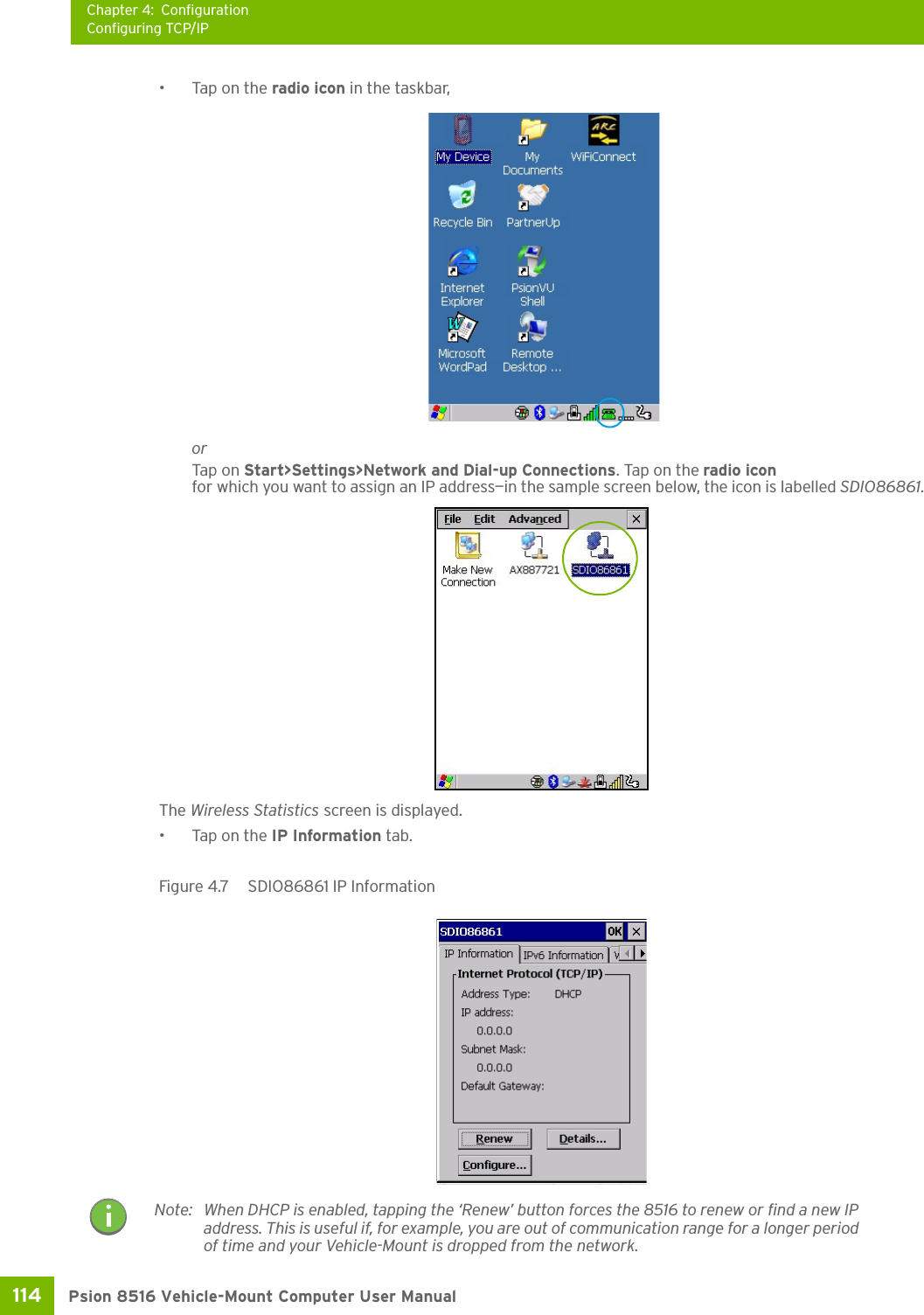
![Chapter 4: ConfigurationConfiguring TCP/IP113 Psion 8516 Vehicle-Mount Computer User Manual4.28.2.7 Connecting the Wireless NetworkYour configured network is listed in the Configure tab. An [X] next to a network indicates that this is the network to which the 8516 will connect.•Tap on the Connect button to activate your network.The Status tab is displayed. The Status field displays ASSOCIATING while the 802.11a/b/g/n radio attempts to connect to the network. Once the association is complete, the Status tab is populated with the appropri-ate information about your network.4.28.3 Configuring TCP/IPIf your network is not using a DHCP server, you will need to assign an IP address.4.28.3.1 IP AddressTo assign an IP address for your 8516:](https://usermanual.wiki/Psion/8516.User-Manual-3/User-Guide-1876108-Page-18.png)
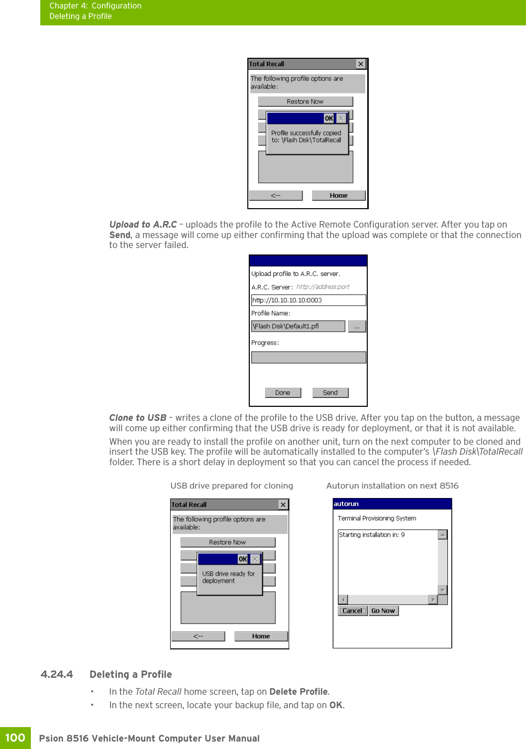
![Chapter 4: ConfigurationWi-Fi Config: Advanced115 Psion 8516 Vehicle-Mount Computer User ManualTo define a static IP address:•Tap on the Configure button.• Tap on the radio button next to Specify an IP address to select it.•Type an IP, Subnet Mask and Default Gateway address in the appropriate fields. Press [ENTER] to save your information.4.28.3.2 Name Server•In the SDIO86861 IP Information tab (see Figure 4.7), tap on the Configure button.•Tap on the Name Servers tab.The DNS and WINS fields in the Name Servers tab allow you to specify additional WINS and DNS resolvers. The format for these fields is ###.###.###.###.4.28.4 Wi-Fi Config: Advanced Use Windows to configure my wireless settingsIn the Advanced tab you can set Windows to configure the radio, using Wireless Zero Config. • Tap on the checkbox to the left of Use Windows to configure my wireless settings to enable this option.Note: If DHCP is enabled, name server addresses are assigned automatically.](https://usermanual.wiki/Psion/8516.User-Manual-3/User-Guide-1876108-Page-20.png)
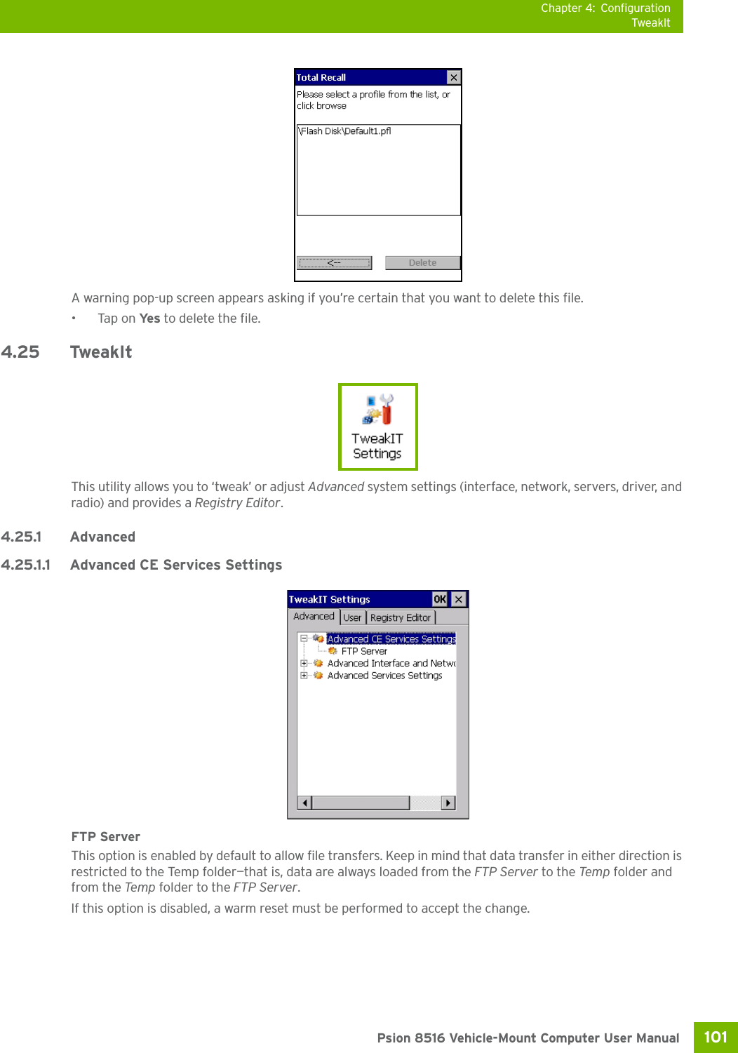
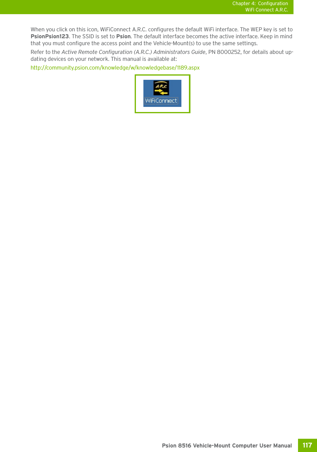
![Chapter 4: ConfigurationMonitoring the Network ConnectionPsion 8516 Vehicle-Mount Computer User Manual116 Power Save ModeThis allows you to set the 802.11 power saving mode of the radio to: CAM (continuous access—always on) (recommended); or MAX_PSP (maximum power saving mode). Roaming - RSSI ThresholdThis sets the RSSI threshold value, below which the radio will start scanning for new access points when roaming. Values range from -55 to -90 dBm.Roaming - AP DeltaThis sets how much greater (in dBm) the RSSI of a new access point must be than the RSSI of the currently associated access point in order for the Vehicle-Mount to initiate a roam. Values range from 5 to 30 dBm. Concluding the Wi-Fi ConfigurationIf you’ve made changes in the Advanced menus, you will need to warm reset your 8516.•Choose Start>Shutdown>Warm Reset.• A dialog box is displayed letting you know that you will lose all unsaved data. Tap on OK. Once the reset is complete, if you checked the box next to Use Windows to configure my wireless set-tings, the Wireless Zero Config screen is displayed on the Vehicle-Mount. Refer to Appendix F: “Wireless Zero Config Settings” for details.4.28.5 Monitoring the Network ConnectionThe radio signal icon in the taskbar indicates the strength of the communication link with an 802.11 access point. To access the radio signal icon:• Tap on the radio icon in the taskbar to display the wireless statistics dialog box.To access the radio signal icon using the keyboard:• Press the [Windows] key to display the Start Menu.• Highlight Shortcuts and then choose System Tray from the sub-menu.• Use the [LEFT] and [RIGHT] arrow keys to highlight the radio signal icon in the taskbar.• Press [ENTER] to display the Wireless Statistics dialog box.4.29 WiFi Connect A.R.C.The WiFiConnectARC utility on the desktop provides a quick method to configure a device for use on a private network, primarily for use with Active Remote Configuration (A.R.C.). Tap here to add a checkmarkto activate the Windows radioconfiguration.Note: Moving in and out of the radio coverage area can have varying effects on a network session. At times, you may need to renew your connection by logging in again.](https://usermanual.wiki/Psion/8516.User-Manual-3/User-Guide-1876108-Page-21.png)
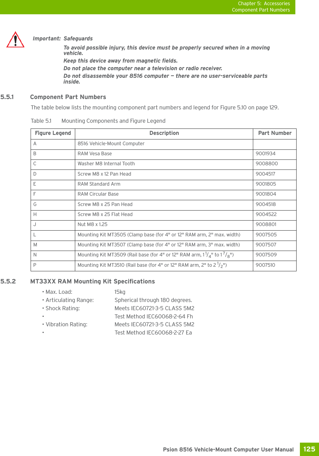
![Chapter 5: AccessoriesPositioning the 8516129 Psion 8516 Vehicle-Mount Computer User Manual1. Use the supplied bolt hole pattern to drill the required holes in the local platform. Hole diameters must not exceed 10mm [13/32 inches]. Hardware (G, H, C, and J) for securing RAM Bases (B or F) to the local platform are in the recommended sizes (see Table 5.1 on page 125). If replacement hardware is required, it should be consistent with these diameters. All fasteners must use a suitable locking mech-anism to ensure that they do not loosen under shock and vibration. • If you are assembling with the RAM Vesa Base, see Section 5.5.4.1:“RAM Vesa Base”.• If you are assembling with the RAM Circular Base, see Section 5.5.4.2:“RAM Circular Base”. 5.5.4.1 RAM Vesa BaseSee Figure 5.10 on page 129. In four places, insert screw (G) through the RAM Vesa Base (B), the local plat-form and the washer (C). Affix with nut (J). Torque to 26 in-lbs. Secure RAM Standard Arm (E) by inserting RAM Balls into both ends of arm sockets.5.5.4.2 RAM Circular Base See Figure 5.10 on page 129. In four places, insert screw (H) through the RAM Circular Base (F), the local platform and the washer (C). Affix with nut (J). Torque to 26 in-lbs. Secure RAM Standard Arm (E) by insert-ing RAM Balls into both ends of sockets.Figure 5.10 RAM Vesa Base RAM Circular Base5.5.5 Positioning the 8516Place the 8516 into the position best corresponding to the RAM hardware used (see Figure 5.11 on page 130) and tighten by hand until secure. Refer to “8516 Mounting Accessories: Installing the RAM Mounting Kit” on page 124 for warnings and proper tightening technique. Mount orientations shown in Figure 5.11 are consid-ered the preferred configurations for the Circular Base to Platform and the Vesa Base to Platform. EJBCGECJHF](https://usermanual.wiki/Psion/8516.User-Manual-3/User-Guide-1876108-Page-29.png)
![Appendix C: Imager & Camera SettingsRequired AppletsC-3 Psion 8516 Vehicle-Mount Computer User ManualThe Imagers applet is used to create, modify, delete, and activate imager settings. The principal uses of the application are to decode barcodes and to capture images. This imager services application is used for cameras and imagers to configure linear (1D), stacked linear, matrix (true 2D) and postal barcodes. A Dem-onstration Application is provided to demonstrate how the imager works. Refer to “Demo” on page 27 for details.C.1 Required AppletsIn order to configure imaging, the Manage Triggers applet must be present in the Control Panel, along with the Imagers applet. C.2 Presets There are two methods that can be used to configure an imager using the Imagers applet:• Use a predefined preset.• Create a custom preset based on a predefined preset.A preset is a group of exposure and image correction settings. Each preset configures the imager for a spe-cific purpose such as barcode decoding or image capture.Presets also allow easier and faster configuration of the imager after power-on or resume from suspend.The predefined presets are generic and satisfy most user requirements. A custom preset can be created for a specific user application, such as: include only specified barcodes, read only a specified number of bar-codes or for reading unusual media.Every preset belongs to a preset type. The following preset types are available:• Imaging for photo capture.• Imaging for barcode decoding.• Symbology selection.At any time, only one preset of each type can be designated as the user-selected active preset.C.2.1 Predefined PresetsPredefined presets are built into the imaging software and cannot be changed. The predefined presets allow you to use the imager to perform specified tasks without having to understand and set numerous var-iables. In almost all cases these predefined presets are sufficient.C.2.2 Barcode Predefined Presets (Barcoding Menu)These presets encompass the majority of the most popular barcodes and their subtypes. The barcode de-coding symbology predefined presets define which barcodes can be decoded. The barcode decoding camera predefined presets determine how the barcode images are captured. C.2.2.1 Barcode Decoding Symbology Predefined PresetsThe following presets select groups of similar barcodes for decoding.Note: The Imagers icon is only displayed when the appropriate imager is installed in your 8516. If there is an imager installed but this icon is not present, additional software (ICS) may need to be installed.To enable a newly-installed imager, press and hold down the [FN] key and the [ENTER/Power] key simultaneously for a minimum of three seconds. Important: It is strongly recommended that a predefined preset is used whenever possible. Each predefined preset contains a coherent group of settings that are known to work together in the intended environment. In almost all situations, at least one of the predefined presets results in a satisfactory outcome.](https://usermanual.wiki/Psion/8516.User-Manual-3/User-Guide-1876108-Page-40.png)
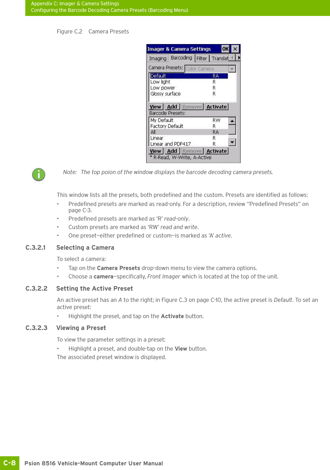
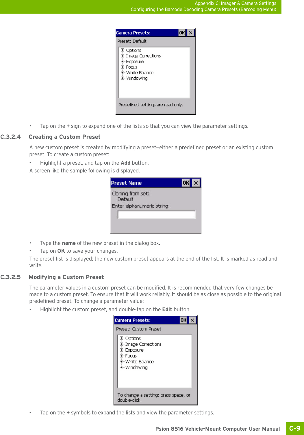
![Appendix C: Imager & Camera SettingsConfiguring the Barcode Decoding Camera Presets (Barcoding Menu)C-7 Psion 8516 Vehicle-Mount Computer User Manual•Tap on the + symbols to expand the lists so that you can view the parameter settings.• Scroll through the parameter list until you reach the parameter that you want to change.• For a parameter that can take a range of values:- Highlight the parameter, and then press the [SPACE] key or double-click on the parameter.- An associated dialog box containing the valid range of values for the parameter and the current setting like the sample screen following is displayed.- Type a value in the field provided.• For a parameter that toggles between two values such as on or off and enabled or disabled:- Highlight the parameter and then press the [SPACE] key, or double-click on the parameter. Either method toggles between the two available values.• When you’ve completed your edits, tap on OK.The parameter list is displayed; the new value for the changed parameter is shown.•Tap on OK to exit to the preset list and save the changes.C.3.1.6 Removing a Custom Preset• Highlight the custom preset you want to delete, and tap on the Remove button.A window is displayed warning you that you are about to remove a preset.•Tap on Ye s to remove the preset or No to cancel the operation.C.3.2 Configuring the Barcode Decoding Camera Presets (Barcoding Menu)To configure the barcode decoding camera presets:•Tap on Sta>Settings>Control Panel>Imagers.•Tap on the Barcoding tab.](https://usermanual.wiki/Psion/8516.User-Manual-3/User-Guide-1876108-Page-44.png)
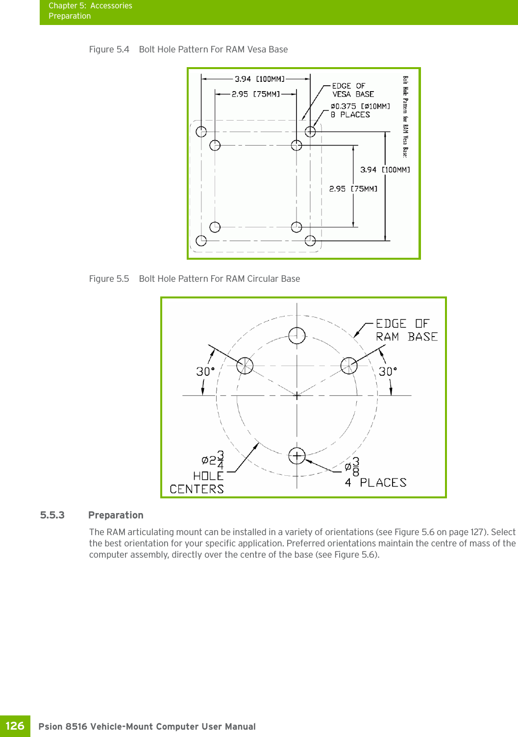
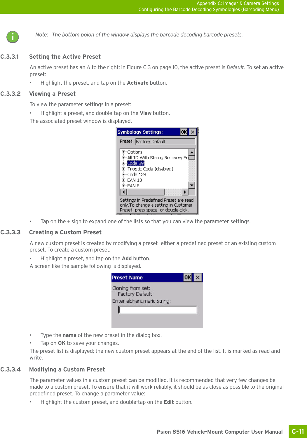
![Appendix C: Imager & Camera SettingsConfiguring the Barcode Decoding Symbologies (Barcoding Menu)Psion 8516 Vehicle-Mount Computer User ManualC-10 • Scroll through the parameter list until you reach the parameter that you want to change.• For a parameter that can take a range of values:- Highlight the parameter, and then press the [SPACE] key or double-click the parameter.- An associated dialog box containing the valid range of values for the parameter and the current setting like the sample screen following is displayed.- Type a value in the field provided.• For a parameter that toggles between two values such as on or off and enabled or disabled:- Highlight the parameter and then press the [SPACE] key, or double-click on the parameter. Either method toggles between the two available values.• When you’ve completed your edits, tap on OK.The parameter list is displayed; the new value for the changed parameter is shown.•Tap on OK to exit to the preset list and save the changes.C.3.2.6 Removing a Custom Preset• Highlight the custom preset you want to delete, and tap on the Remove button.A window is displayed warning you that you are about to remove a preset.•Tap on Ye s to remove the preset or No to cancel the operation.C.3.3 Configuring the Barcode Decoding Symbologies (Barcoding Menu)To configure the barcode decoding camera presets:•Tap on Sta>Settings>Control Panel>Imagers.• Tap on the Barcoding tab.Figure C.3 Viewing Barcode Decoding Symbologies](https://usermanual.wiki/Psion/8516.User-Manual-3/User-Guide-1876108-Page-47.png)
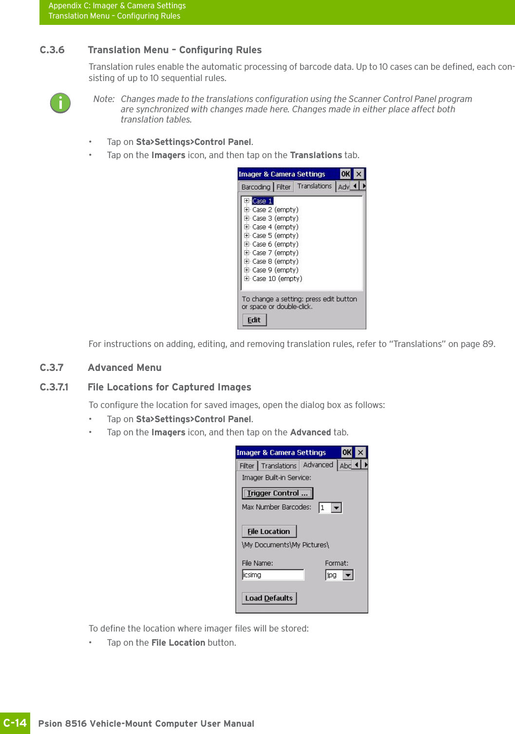
![Appendix C: Imager & Camera SettingsBarcoding Menu – Configuring SymbologiesPsion 8516 Vehicle-Mount Computer User ManualC-12 • Tap on the + symbols to expand the lists and view the parameter settings.• Scroll through the parameter list until you reach the parameter that you want to change.• For a parameter that can take a range of values:- Highlight the parameter, and then press the [SPACE] key or double-click the parameter.- An associated dialog box containing the valid range of values for the parameter and the current setting like the sample screen following is displayed.- Type a value in the field provided.• For a parameter that toggles between two values such as on or off and enabled or disabled:- Highlight the parameter and then press the [SPACE] key, or double-click on the parameter. Either method toggles between the two available values.• When you’ve completed your edits, tap on OK.The parameter list is displayed; the new value for the changed parameter is shown.•Tap on OK to exit to the preset list and save the changes.C.3.3.5 Removing a Custom Preset• Highlight the custom preset you want to delete, and tap on the Remove button.A window is displayed warning you that you are about to remove a preset.•Tap on Ye s to remove the preset or No to cancel the operation.C.3.4 Barcoding Menu – Configuring SymbologiesTo v iew t he Symbology Settings options:• Tap on the Barcoding tab, highlight All and then double-tap the View button.To edit a default preset, you must first activate it:•Tap on My Default, and tap on the Activate button – an A appears to the right of My Default.Once the preset is activated, you can enable or disable the barcodes the imager will read.• Highlight My Default in the Barcoding tab.• Double-tap on the Edit button.None of the other barcode decoding predefined presets are changed.C.3.4.1 Symbology SettingsNote: For descriptions of the barcode symbologies, review “Barcode Symbologies” on page C-15.](https://usermanual.wiki/Psion/8516.User-Manual-3/User-Guide-1876108-Page-49.png)
![Appendix C: Imager & Camera SettingsFilter Menu – Manipulating Barcode DataC-13 Psion 8516 Vehicle-Mount Computer User ManualC.3.5 Filter Menu – Manipulating Barcode DataTo configure rules for manipulating barcode data:•Tap on Sta>Settings>Control Panel. •Tap on the Imagers icon, and then tap on the Filter tab.C.3.5.1 Modifying a Barcode SettingThe rules for manipulating data from selected barcode symbologies can be modified. To change the set-tings for a symbology:•Tap on the + symbols to expand the lists and view the parameter settings.• Scroll through the parameter list until you reach the parameter that you want to change.• For a parameter that can take a range of values:- Highlight the parameter, and then press the [SPACE] key or double-click the parameter.- An associated dialog box containing the valid range of values for the parameter and the current setting like the sample screen following is displayed.- Type a value in the field provided.• For a parameter that takes a single character:- Highlight the parameter and then press the [SPACE] key, or double-click the parameter. The follow-ing screen is displayed:• When you’ve completed your edits, tap on OK.](https://usermanual.wiki/Psion/8516.User-Manual-3/User-Guide-1876108-Page-50.png)
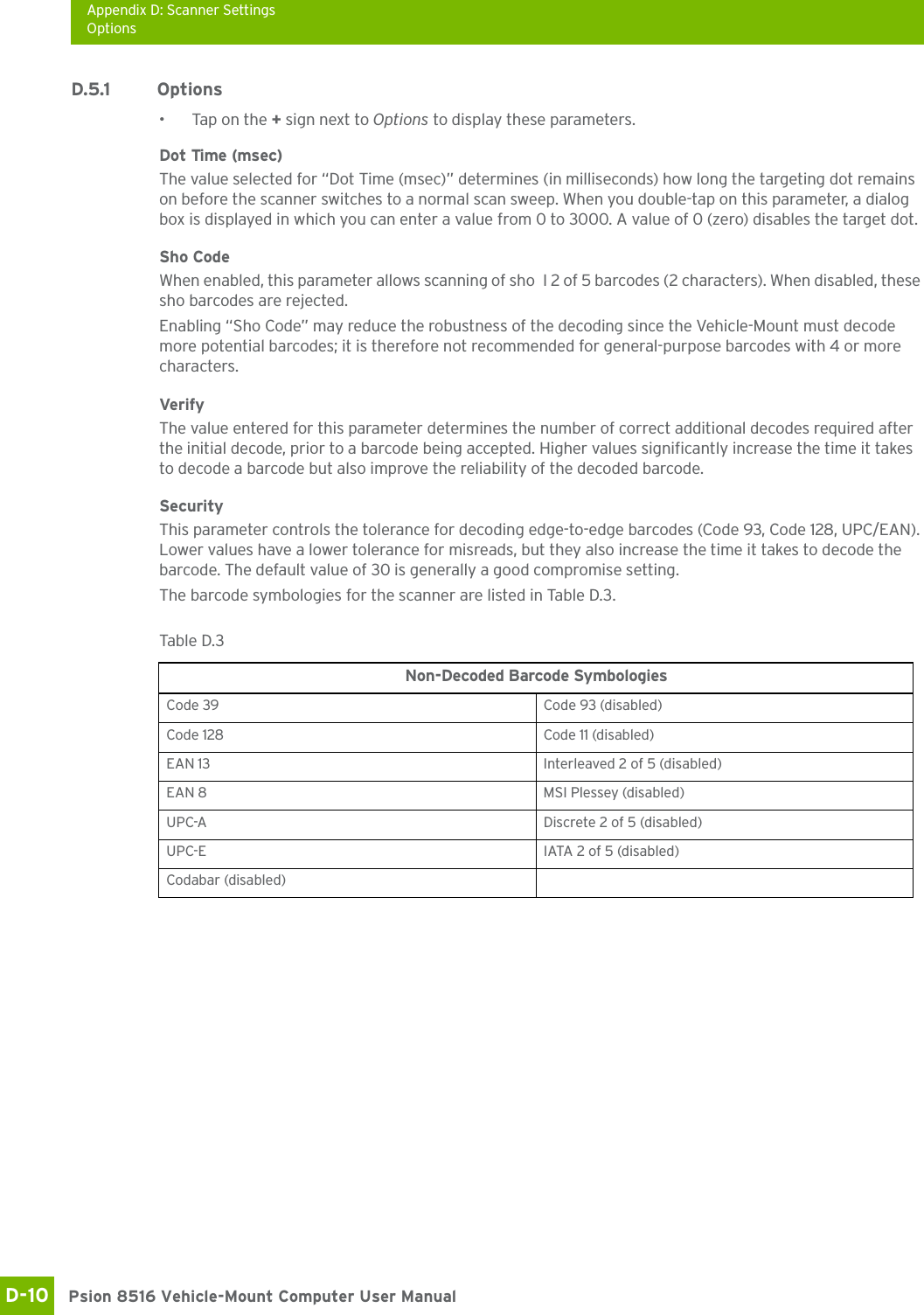
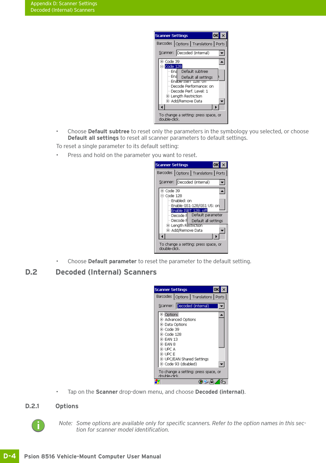
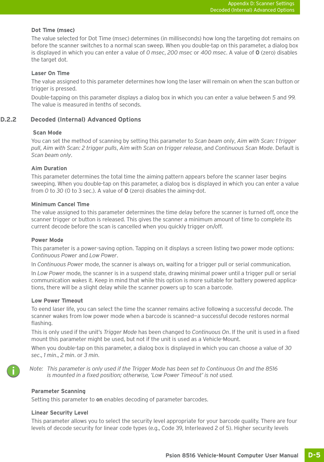
![Appendix D: Scanner SettingsBarcode SettingsD-3 Psion 8516 Vehicle-Mount Computer User ManualD.1 Barcode SettingsThe Scanners icon in the Control Panel provides dialog boxes in which you can tailor barcode scanner con-figurations and choose the barcodes your scanner will recognize.The parameters are preset with the default settings of the decoded scanner installed in the unit. For a listing of available scanners and their specifications, please refer to Chapter A: “8516 Specifications”. D.1.1 Scanner OptionsThe drop-down menu to the right of the Scanner option allows you to choose configurations for one of the following scanner types, depending on what is installed in/on your Vehicle-Mount: Decoded (internal), Decoded (HHP), Decoded (Intermec ISCP, and Non-decoded Scanners.The symbologies listed change to reflect the scanner you choose and the barcodes it suppos. Always defer to your barcode scanner’s programming manual when in doubt about the availability or settings for any pa-rameter. Keep in mind that some barcode types are only available when an internal imaging scanner is installed. All internal scanners can be configured using these dialog boxes. D.1.2 Restoring Default SettingsIf you want to restore the factory defaults after making changes, the defaults can be applied to a selected parameter, sub-tree of parameters, or all scanner parameters. • Press and hold on a symbology (e.g., Code 128) to display a pop up a menu.Important: To enable a newly-installed scanner, press and hold down the [FN] key and the [ENTER/Power] key simultaneously for a minimum of three seconds. For information on configuring the Options, Translations, and Ports settings, see “Scanners” on page 86.Note: Your 8516 comes preconfigured from the factory for internal scanner types. The type of scanner installed can be determined from the System icon in the Control Panel, under the System Propeies tab. Important: To improve the decode speed and performance, enable (set to ‘on’) only those codes that are required by the application.](https://usermanual.wiki/Psion/8516.User-Manual-3/User-Guide-1876108-Page-58.png)
![Appendix D: Scanner SettingsDecoded (Internal) Data OptionsPsion 8516 Vehicle-Mount Computer User ManualD-6 should be selected for decreasing levels of barcode quality. As security levels increase, the scanner’s decode speed decreases.Double-tapping on this parameter displays a dialog box in which you can enter a value from 1 to 4. Linear security level 1 specifies that the following code types must be successfully read twice before being decoded:Linear security level 2 specifies that all types of codes must be successfully read twice before being de-coded.Linear security level 3 specifies that code types other than the following must be successfully read twice before being decoded. The following codes must be read three times:Linear security level 4 requires that all code types be successfully read three times before being decoded.Bi-Direction RedundancyWhen this parameter is enabled, a barcode must be successfully scanned in both directions (forward and re-verse) before being decoded.D.2.3 Decoded (Internal) Data OptionsTransmit Code ID CharA code ID character identifies the scanned barcode type. In addition to any single character prefix already selected, the code ID character is inseed between the prefix and the decoded symbol.When you double-tap on this parameter, a dialog box is displayed in which you can choose a transmit code: None, AIM or Symbol.Scan Data FormatThis parameter allows you to change the scan data transmission format.Double-tapping on Scan Data Format displays the following options from which you can choose a data format: data (as-is), data [S1], data [S2], data [S1][S2], [P] data, [P] data [S1], [P] data [S2] and [P] data [S1][S2].Prefix [P], Suffix [S1] and Suffix [S2]A prefix and/or one or two suffixes may be appended to scan data for use in data editing. When you dou-ble-tap on these parameters, dialog boxes are displayed in which you can enter a value from 0 to 255.Code Type LengthCodabar AllMSI Plessey 4 or lessD 5 of 5 8 or lessI 2 of 5 8 or lessCode Type LengthMSI Plessey 4 or lessD 2 of 5 8 or lessI 2 of 5 8 or lessNote: This parameter is only valid if a “Linear Security Level” is enabled.](https://usermanual.wiki/Psion/8516.User-Manual-3/User-Guide-1876108-Page-61.png)
![Appendix D: Scanner SettingsDecoded (HHP)D-7 Psion 8516 Vehicle-Mount Computer User ManualDelete Char Set ECIsSetting this parameter to on enables the scanner to delete any escape sequences representing Character Set ECIs (Eended Channel Interpretations [also known as GLIs]) from its buffer before transmission. When this parameter is enabled, the scanner transmits data from PDF417 and MicroPDF417 barcodes con-taining Character Set ECIs, even when the ECI Protocol is disabled.ECI Decoder Setting this parameter to on enables the scanner to interpret any Eended Channel Interpretations (ECIs) suppoed by the scanner. This parameter has no effect on symbols that were not encoded using ECIs. If this parameter is set to off and a symbol that was encoded using an ECI escape is scanned, the scanner transmits the ECI escape followed by the uninterpreted data.The barcode symbologies for the scanner are listed in Table D.1.D.3 Decoded (HHP)To configure imagers, please see Appendix C: “Imager & Camera Settings”.D.4 Decoded (Intermec ISCP)•Tap on the Scanner drop-down menu, and choose Decoded (Intermec ISCP).D.4.1 Decoded (ISCP) OptionsLaser On TimeThe value assigned to this parameter determines how long the laser will remain on when the scan button or trigger is pressed.Table D.1 Decoded (Internal) Barcode SymbologiesCode 39 UPC/EAN Shared SettingsTrioptic Code (disabled) Code 93 (disabled)Code 128 Codabar (disabled)EAN 13 MSI Plessey (disabled)EAN 8 Interleaved 2 of 5 (disabled)UPC-A Discrete 2 f 5 (disabled)UPC-E Gs1 DataBar (disabled)](https://usermanual.wiki/Psion/8516.User-Manual-3/User-Guide-1876108-Page-62.png)
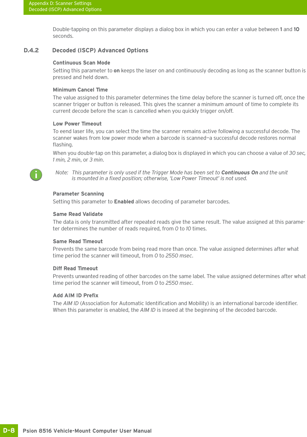
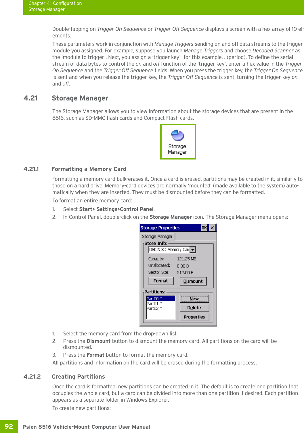
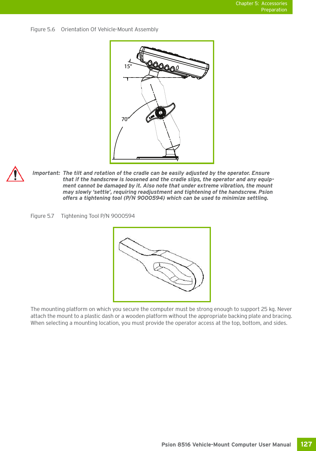
![Appendix D: Scanner SettingsNon-Decoded ScannersD-9 Psion 8516 Vehicle-Mount Computer User ManualThe barcode symbologies for the scanner are listed in Table D.2.D.5 Non-Decoded ScannersFigure D.1 Non-Decoded Scanner Options•Tap on the Scanner drop-down menu, and choose Non-decoded.All the available barcode symbologies for this type of scanner can be selected in this tab.A ‘plus’ sign (+) to the left of the menu item indicates that a sub-menu of parameters is attached.•Tap on the + sign to display the sub-menu.• To change a parameter value, double-tap on the parameter. If you need to type a value, a dialog box is displayed in which you can type a new value. If you need to change a yes or no value, double-tapping on the parameter toggles between yes and no.If you’re using the keyboard:• Highlight the barcode you want to work with, and press the [RIGHT] arrow key to display the sub-menu.• Use the [UP] and [DOWN] arrow keys to highlight a parameter. • To change a parameter value, press [SPACE] or the [RIGHT] arrow key. If a field requires te entry, a te box is displayed in which you can enter the appropriate value.Table D.2 Decoded (Intermec ISCP) Barcode SymbologiesCode 39 TLC-39 (disabled)Code 128 2D PDF-417EAN 13 2D micro PDF-417EAN 8 Discrete 2 of 5 (disabled)UPC-A Telepen (disabled)UPC-E Gs1 DataBar (disabled)UPC/EAN Shared Settings CompositeCode 93 (disabled) TLC-39 (disabled)Codabar (disabled) PDF-417MSI Plessey (disabled) micro PDF-417 (disabled)Code 11 (disabled) CodaBlock F (disabled)Interleaved 2 of 5 (disabled) CodaBlock A (disabled)Matrix 2 of 5 (disabled)](https://usermanual.wiki/Psion/8516.User-Manual-3/User-Guide-1876108-Page-64.png)