Proxim Wireless XB92WLE 802.11 a/n PCIe Module User Manual AntennaInstallationGuide
Proxim Wireless Corporation 802.11 a/n PCIe Module AntennaInstallationGuide
Contents
- 1. User Manual
- 2. Software guide1
- 3. software guide2
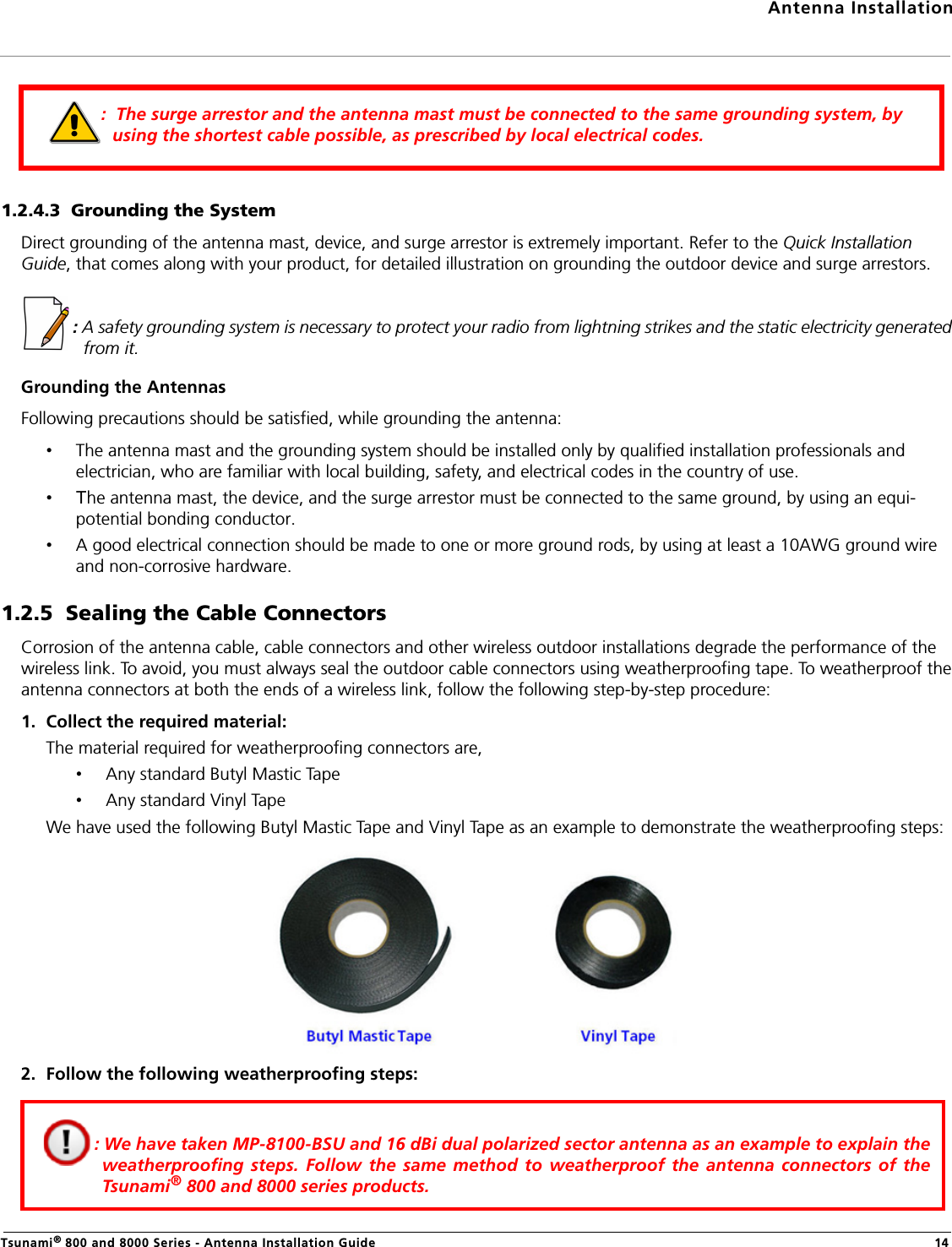
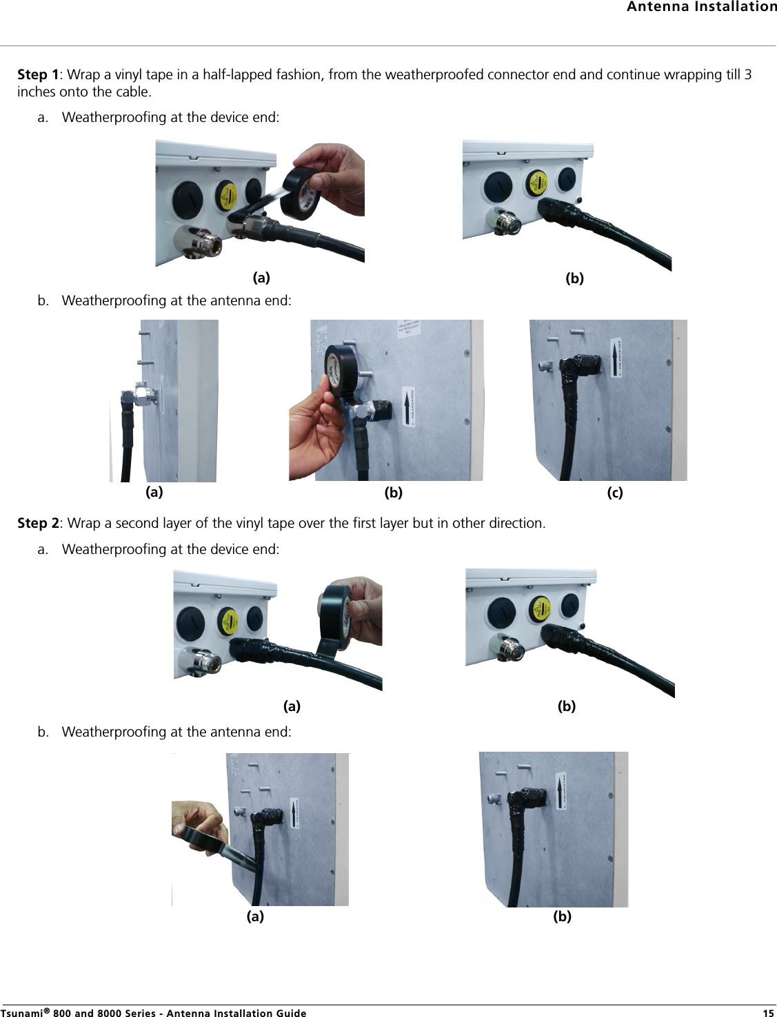
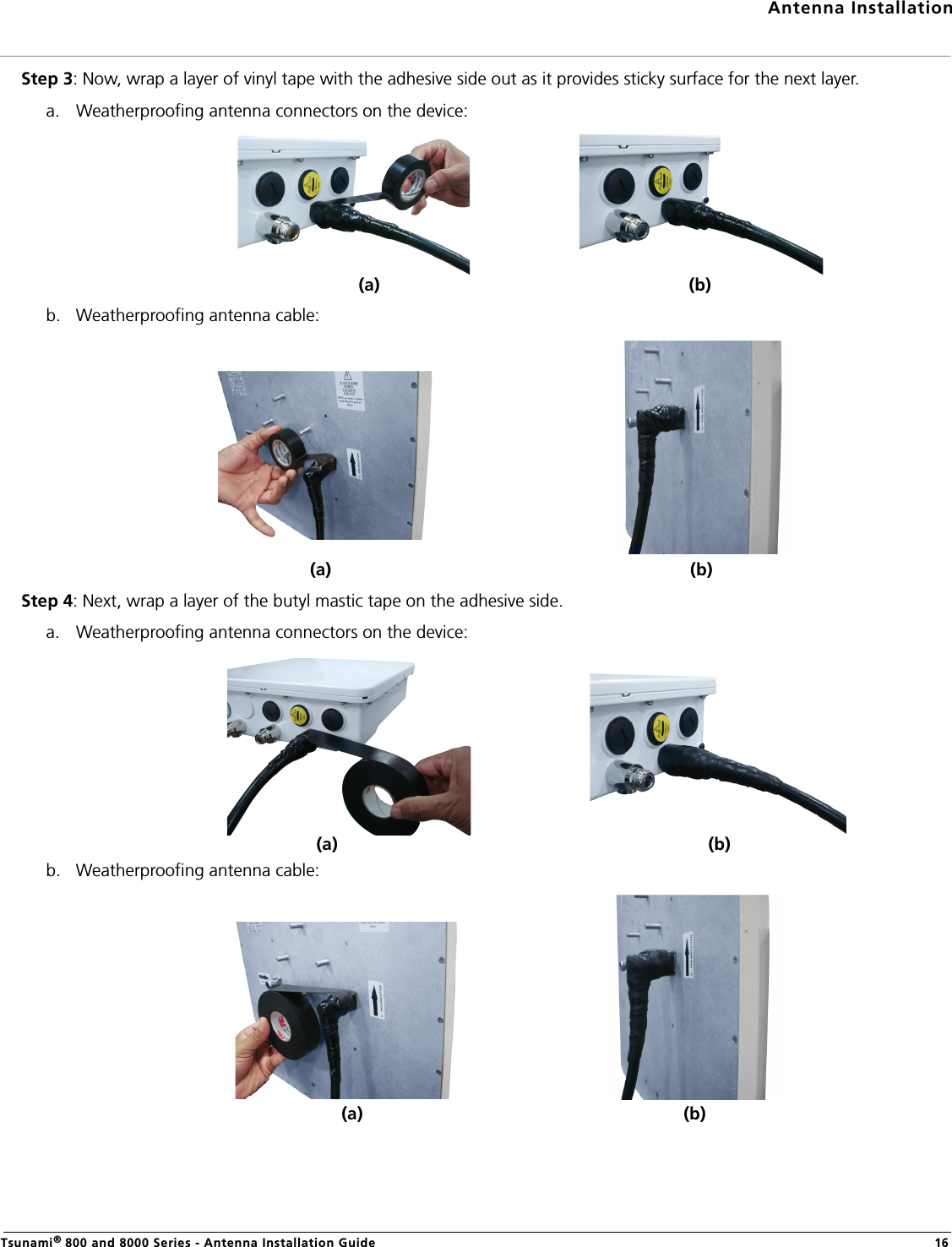
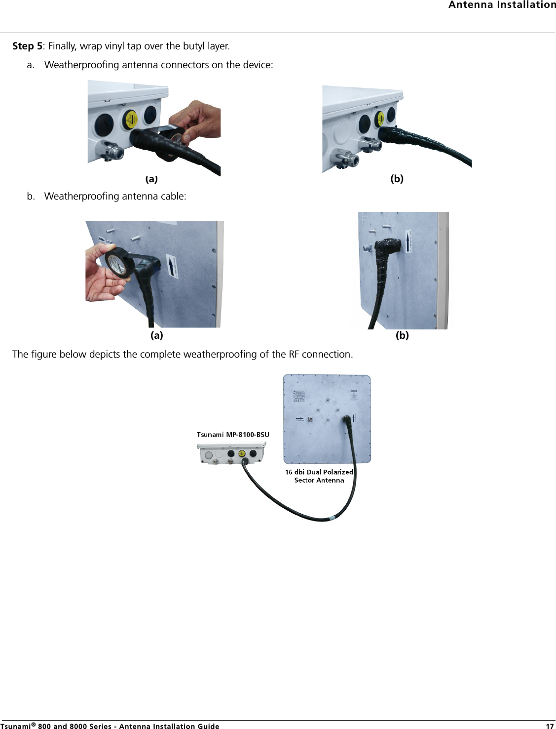
- 4. Antenna installation guide
- 5. EIRP compliance declaration revised
- 6. HW_guide_revised
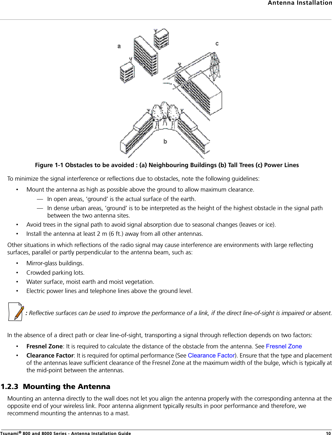
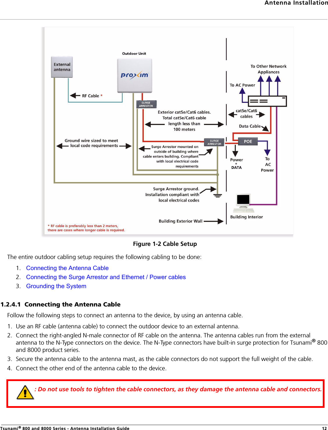
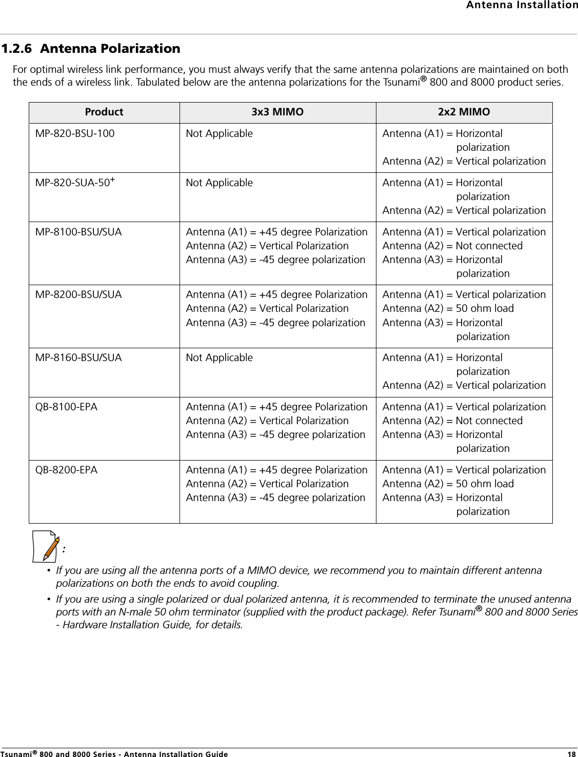
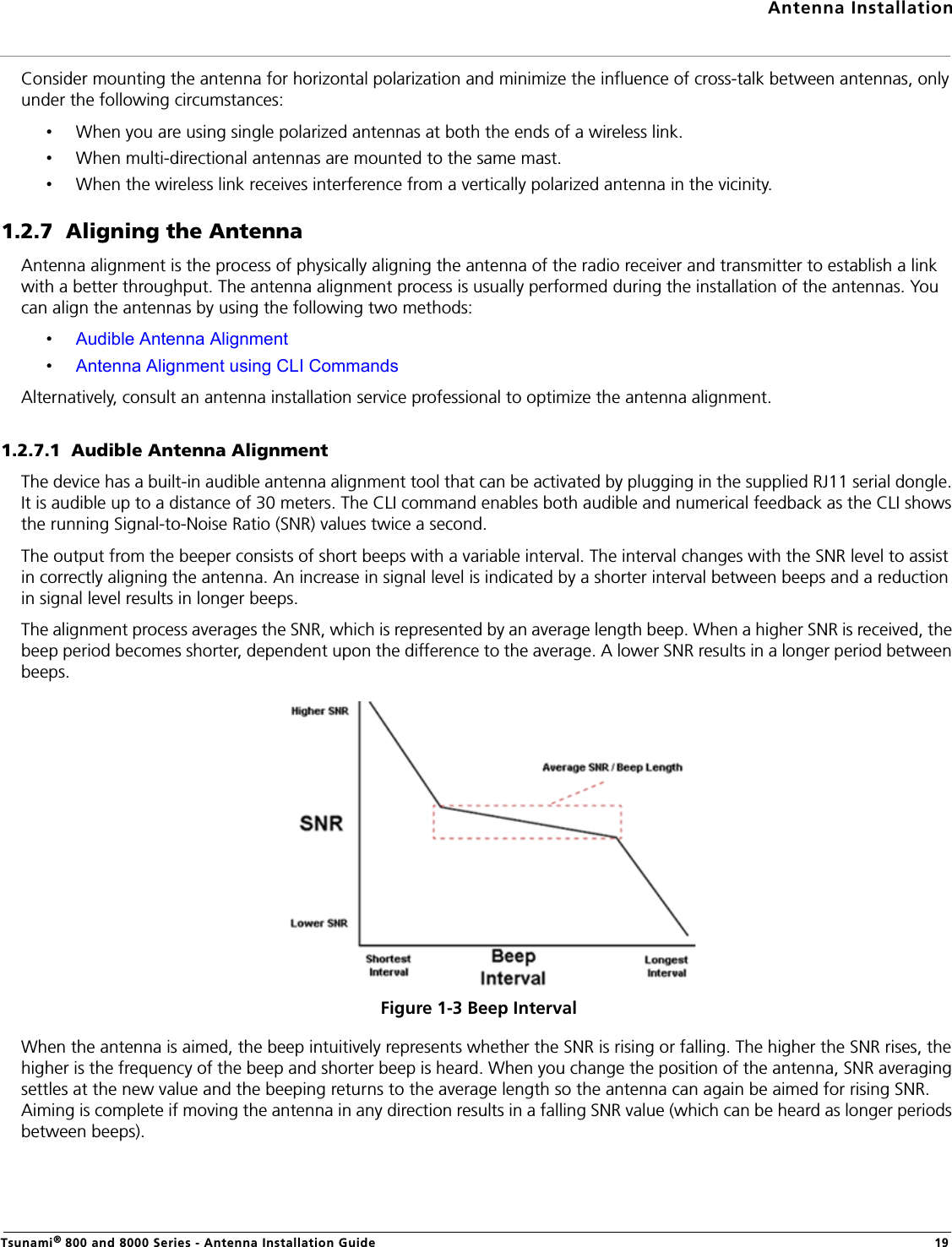
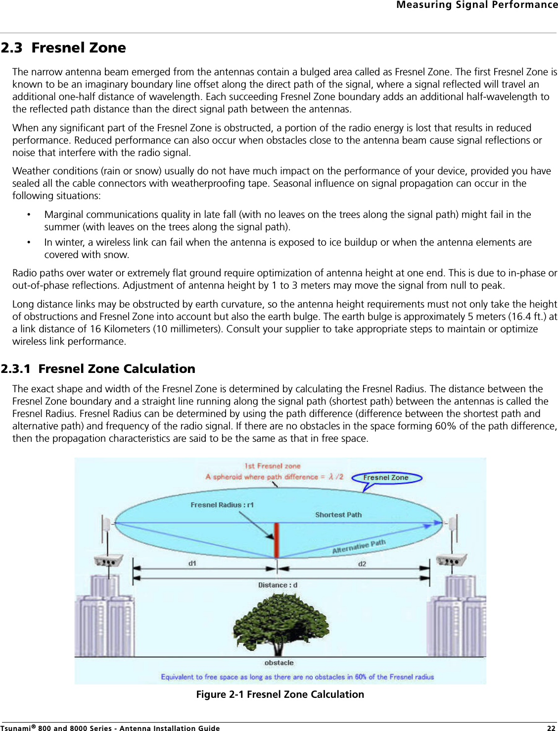
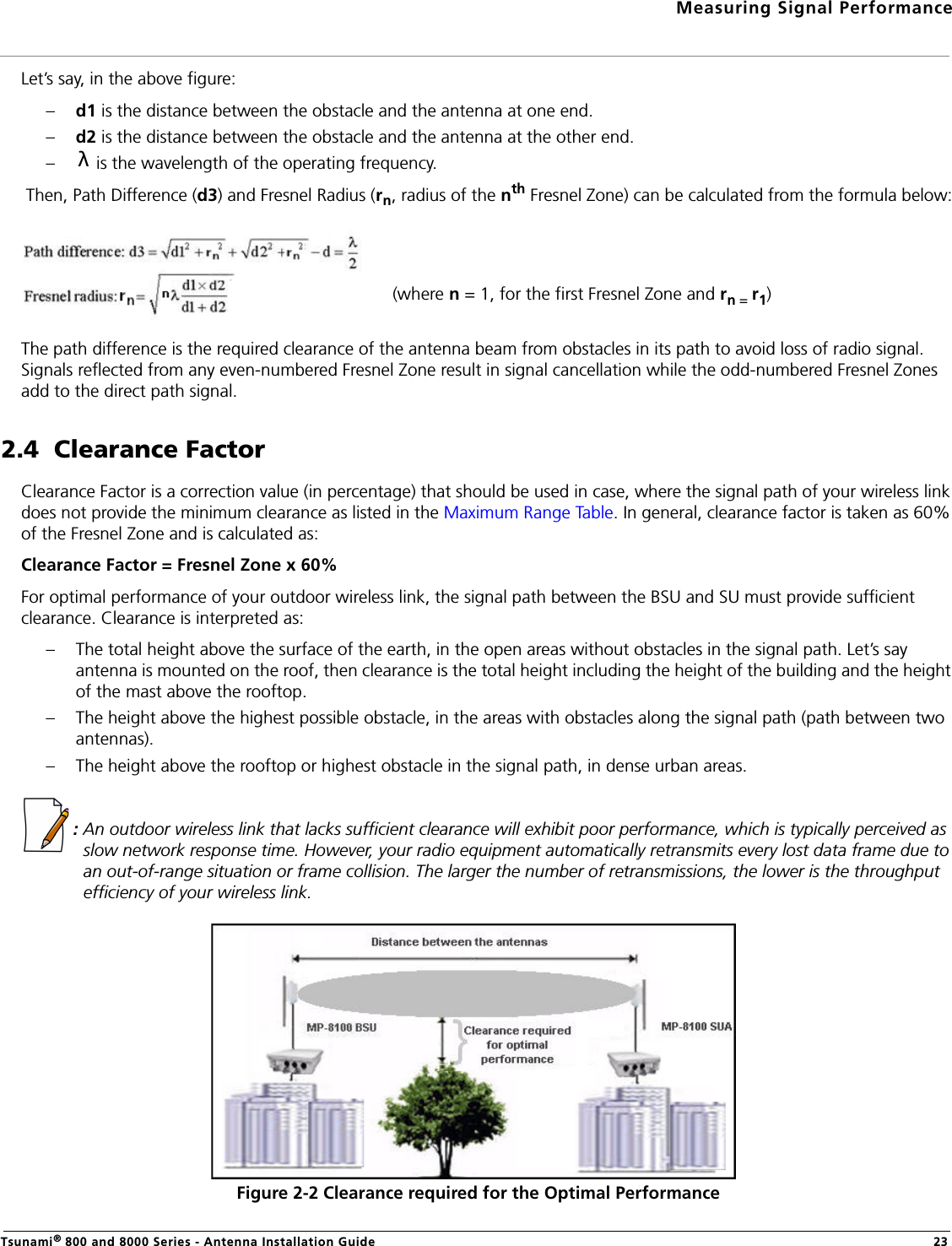
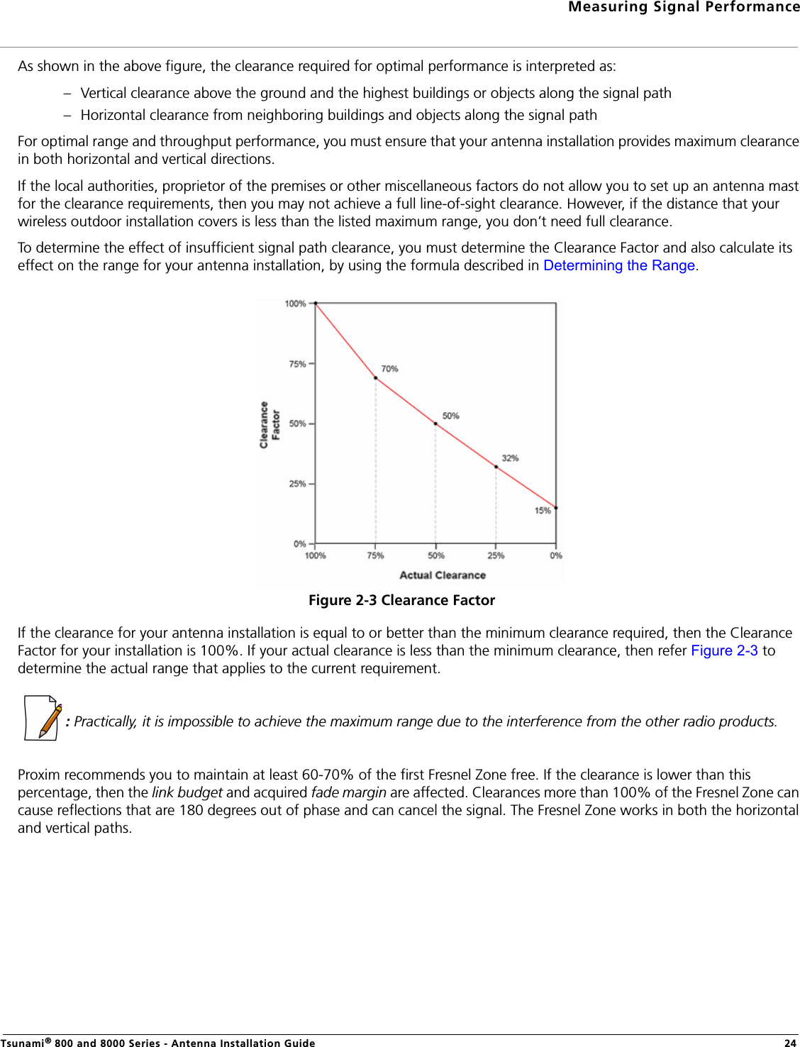
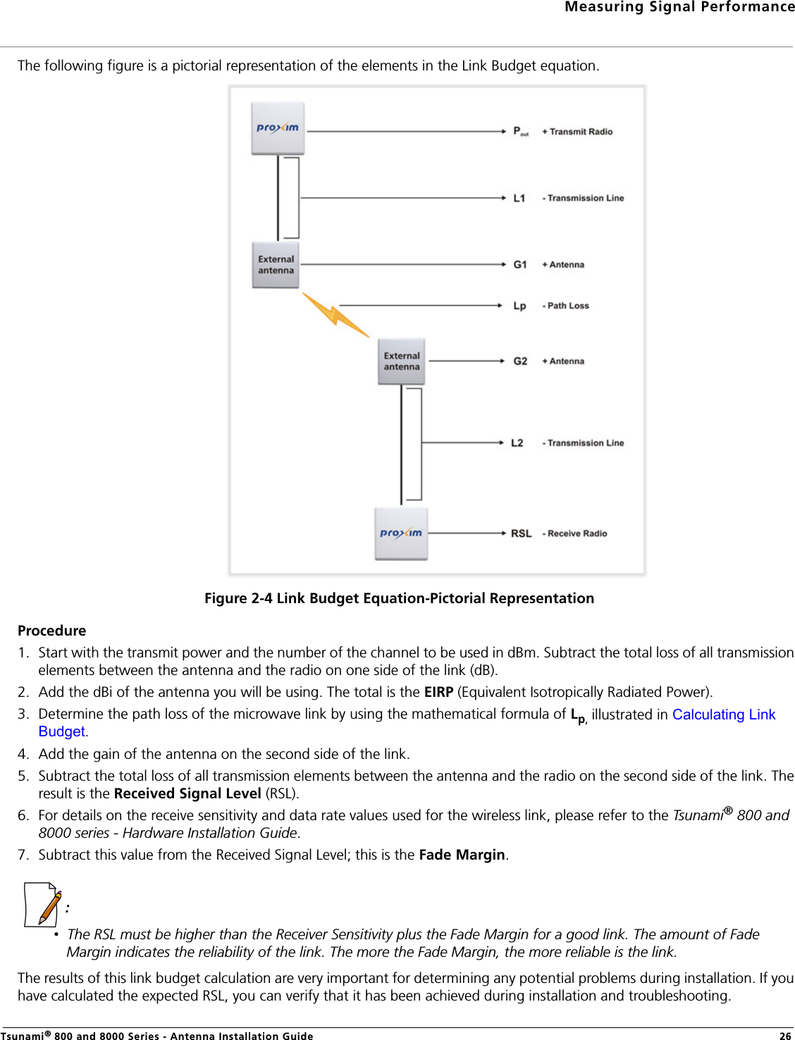
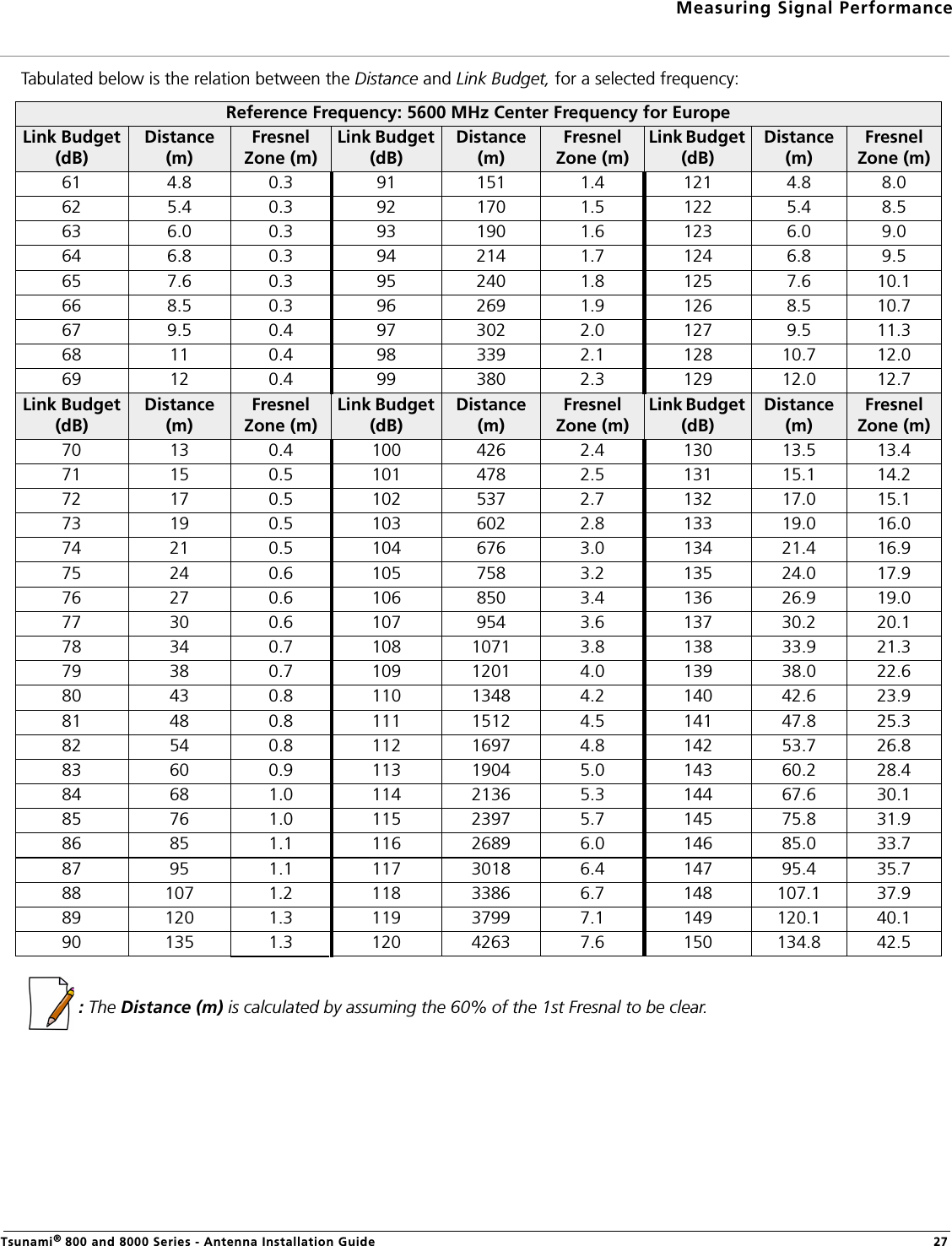
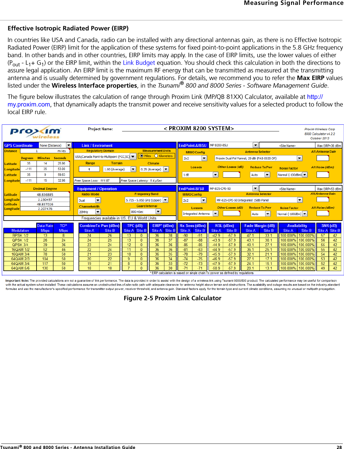
Antenna installation guide