Proxim Wireless S58-S60 Tsunami Multipoint Unlicensed Radio Transceiver User Manual Backing down from TNG CCI 2
Proxim Wireless Corporation Tsunami Multipoint Unlicensed Radio Transceiver Backing down from TNG CCI 2
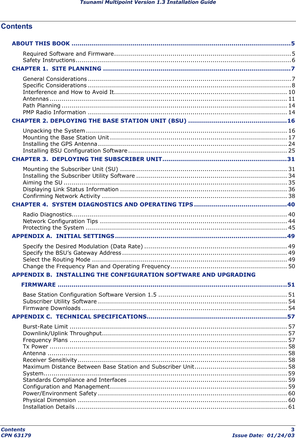
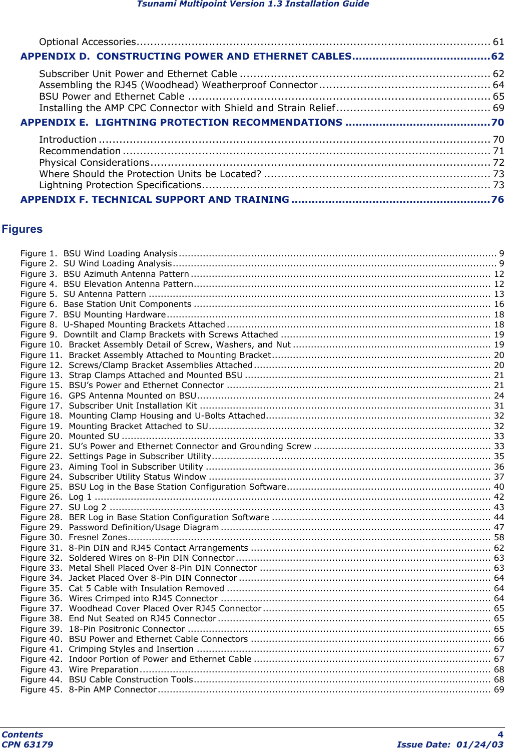
Contents
- 1. Antenna Manual
- 2. Users Manual Part 2
- 3. Users Manual Part 1
- 4. Users Manual Part 1 cont
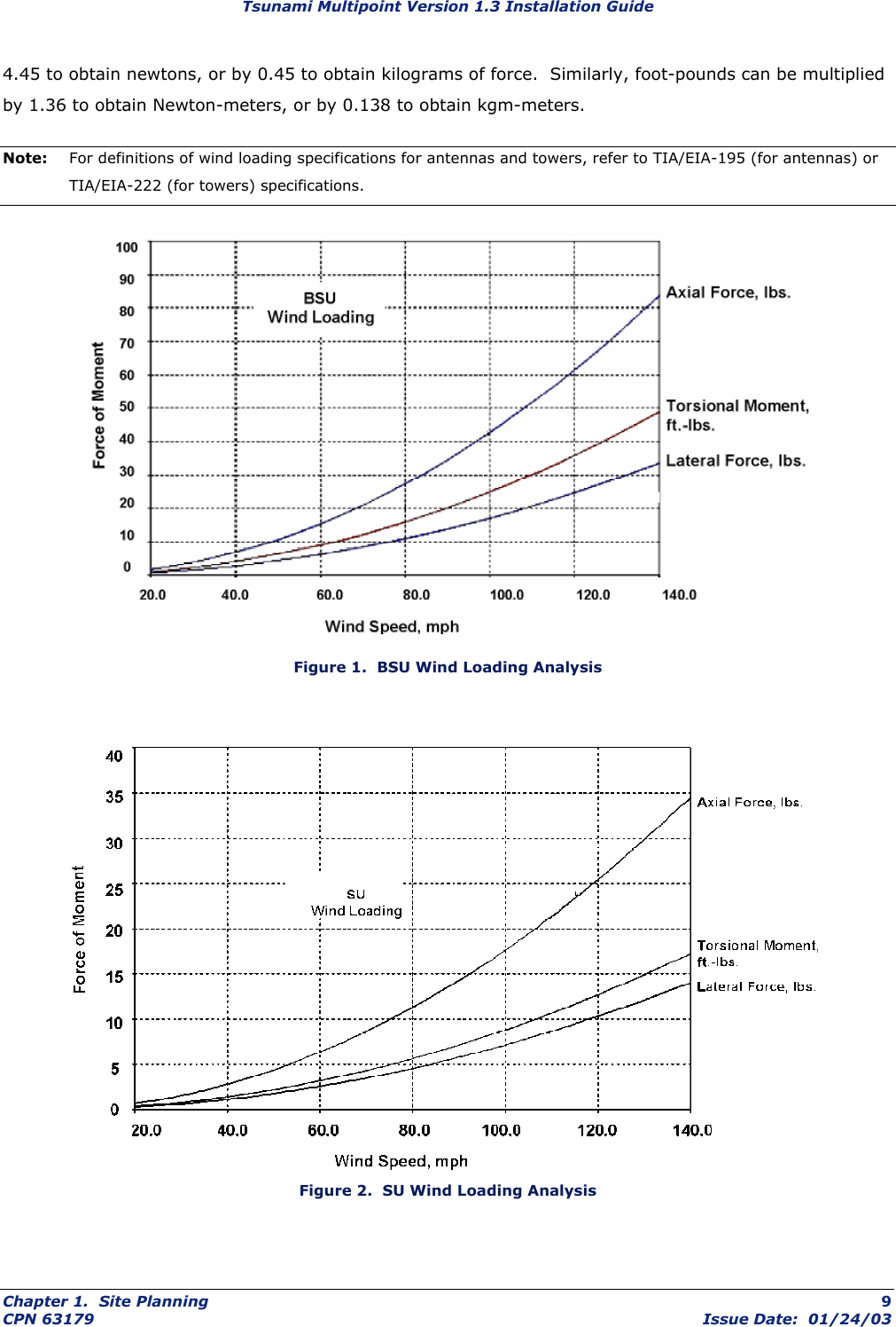
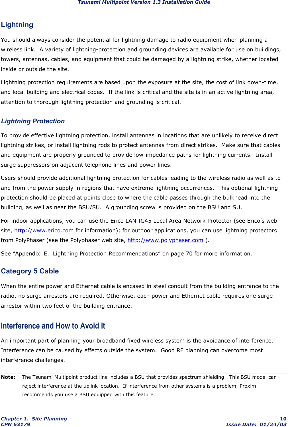
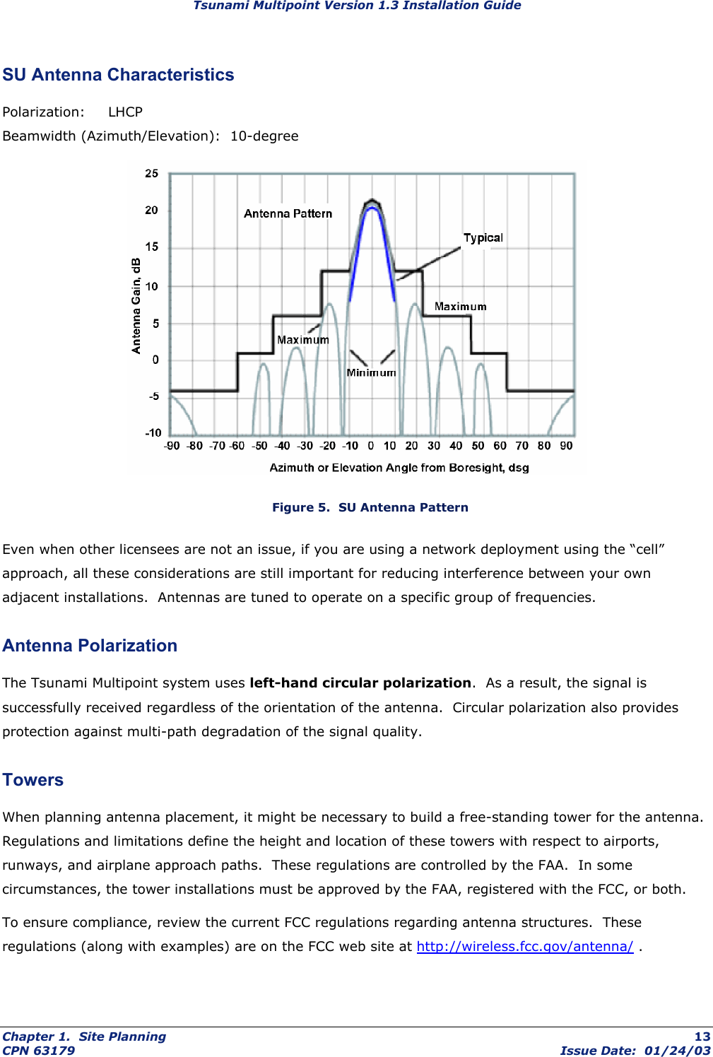
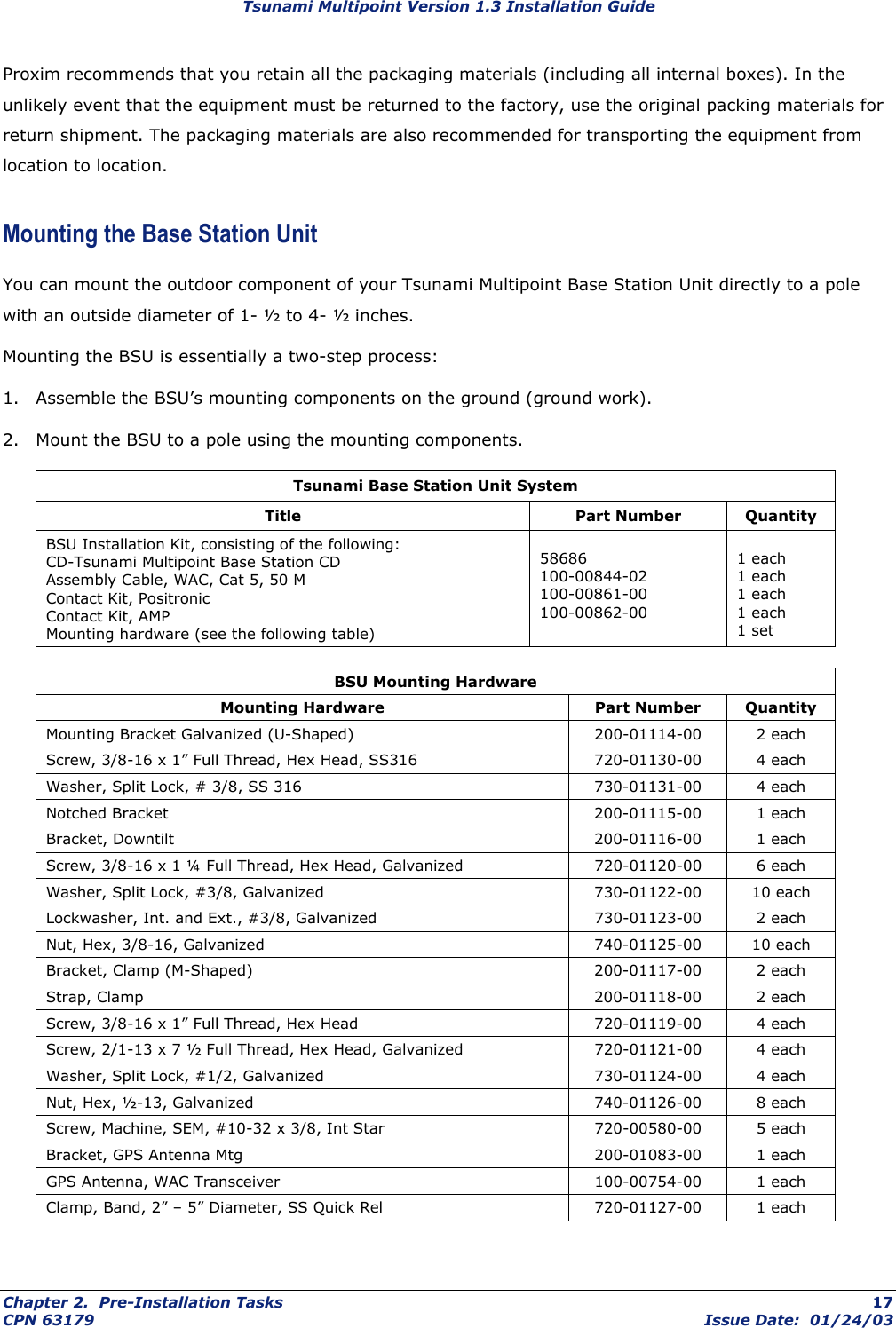
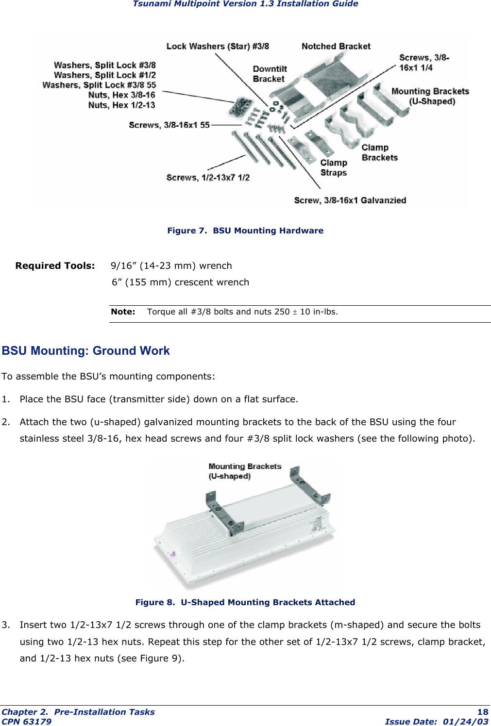
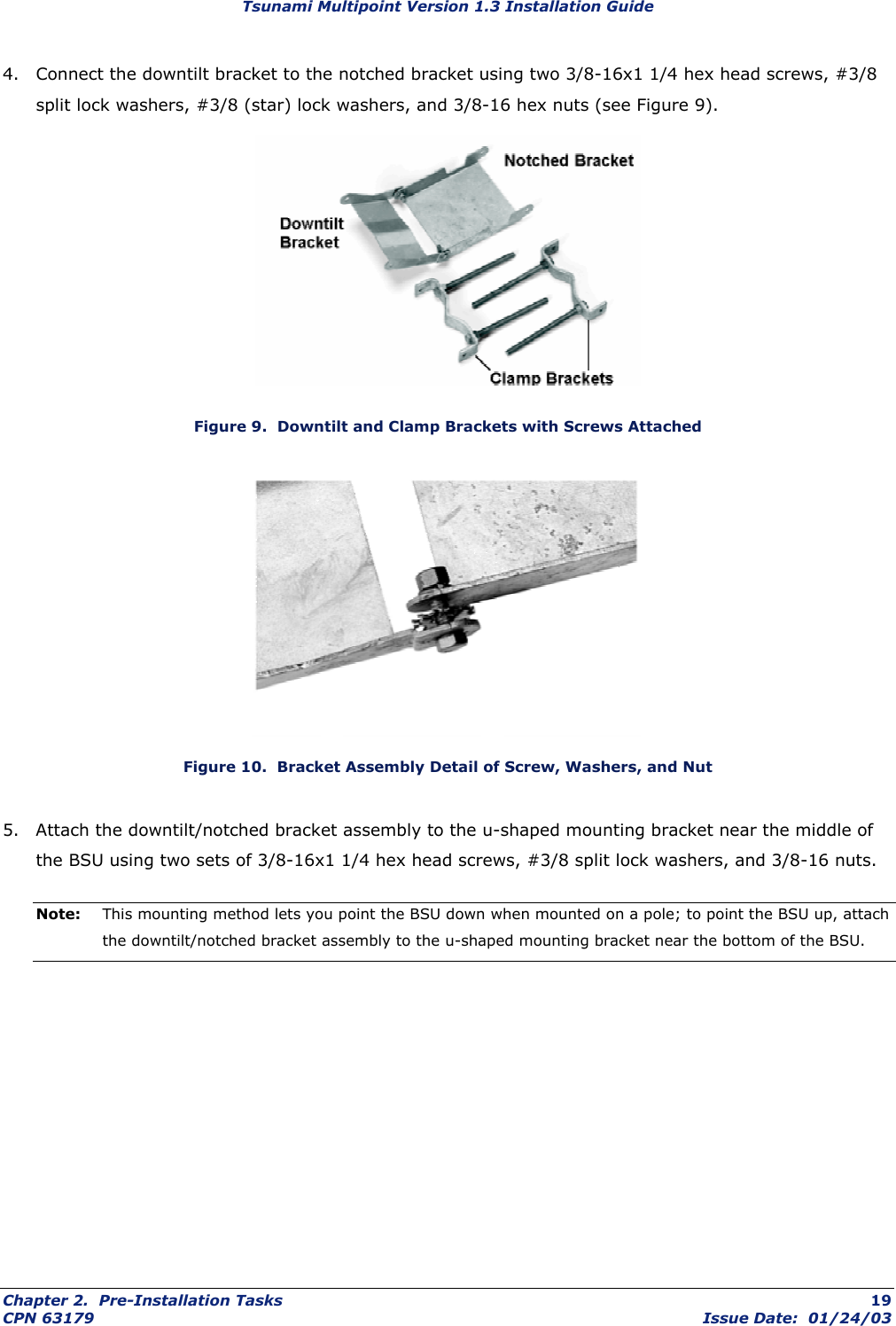
Users Manual Part 1