Proxim Wireless S58-GX1 Unlicensed DTS User Manual Lynx
Proxim Wireless Corporation Unlicensed DTS Lynx
UserManual.wiki
>
Proxim Wireless
>
S58-GX1 User Manual
>
Manual Pages 54 55
Contents
1.
Manual Part 1
2.
Manual Part 2
3.
Installation Manual
4.
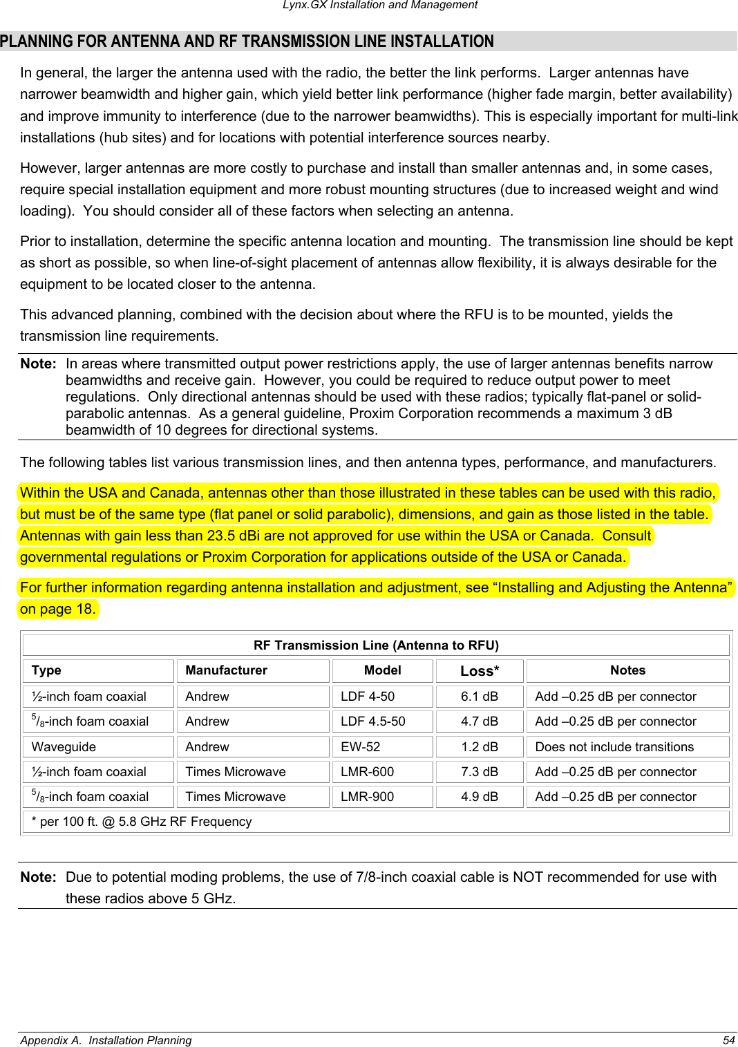
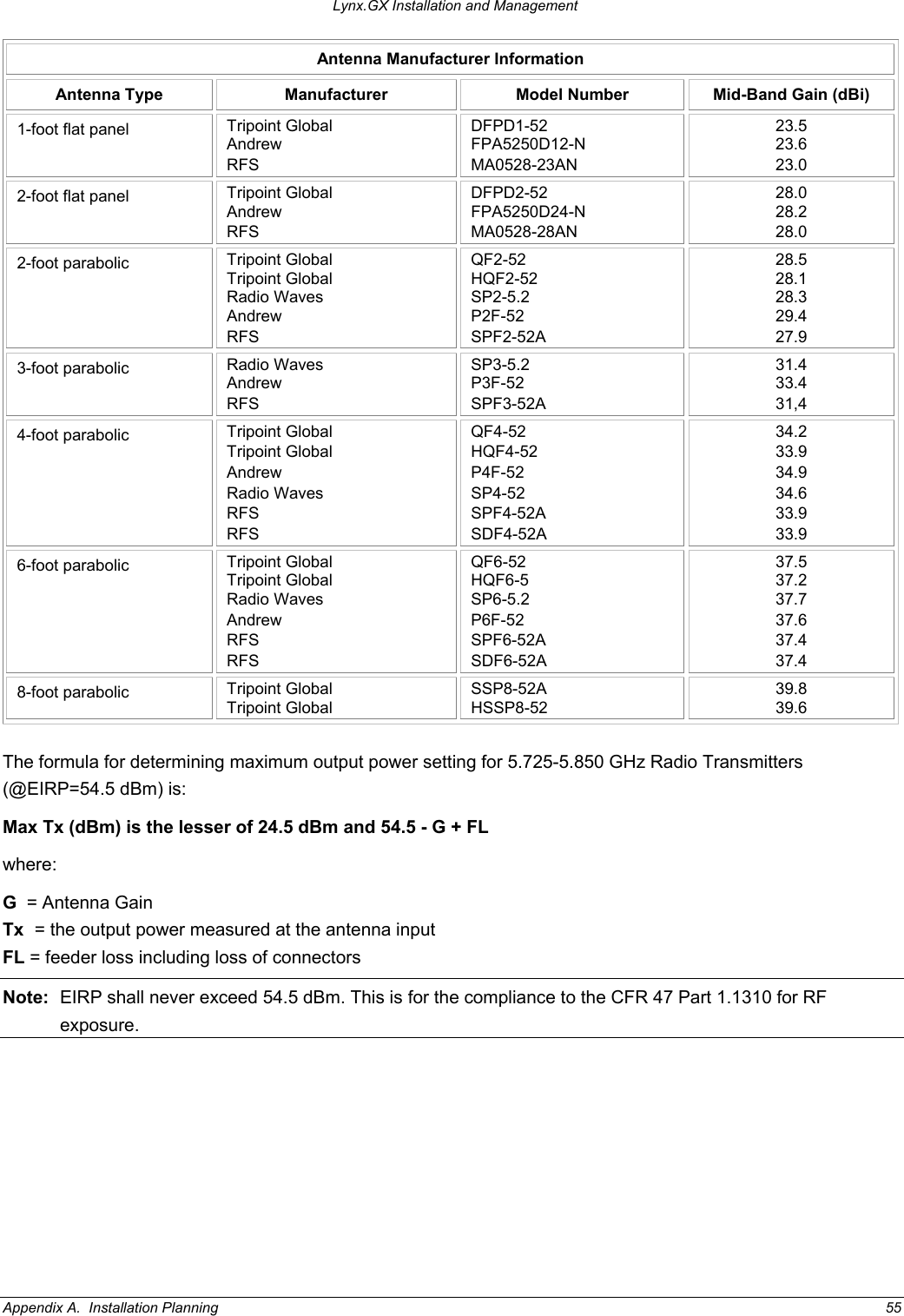
Manual Pages 54 55
5.
Revised Installation Statement
Manual Pages 54 55
Navigation menu
Upload a User Manual
Namespaces
Wiki Guide
HTML
PDF
Info
Views
User Manual
Discussion / Help
Navigation