Proxim Wireless PROXMB92 miniPCI High Power MIMO IEEE 802.11 a/b/g/n RFModule User Manual QB 8100 100 5 Mbps Models User Guide
Proxim Wireless Corporation miniPCI High Power MIMO IEEE 802.11 a/b/g/n RFModule QB 8100 100 5 Mbps Models User Guide
Contents
- 1. Users Manual
- 2. user manual
- 3. Module user manual
- 4. System user manual
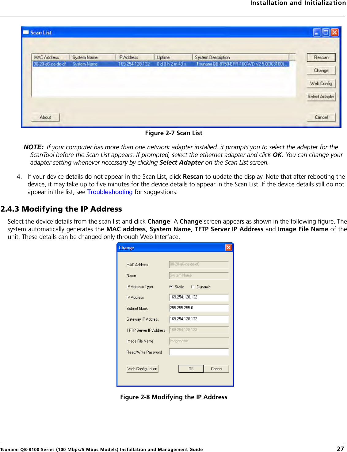
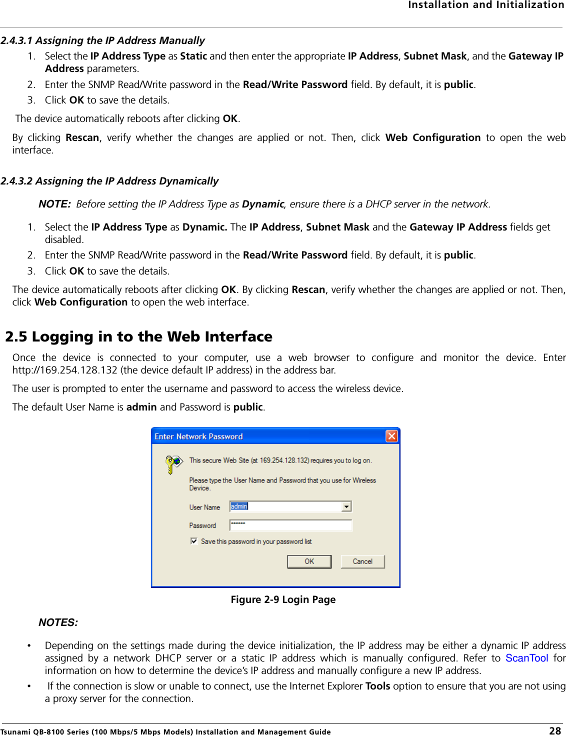
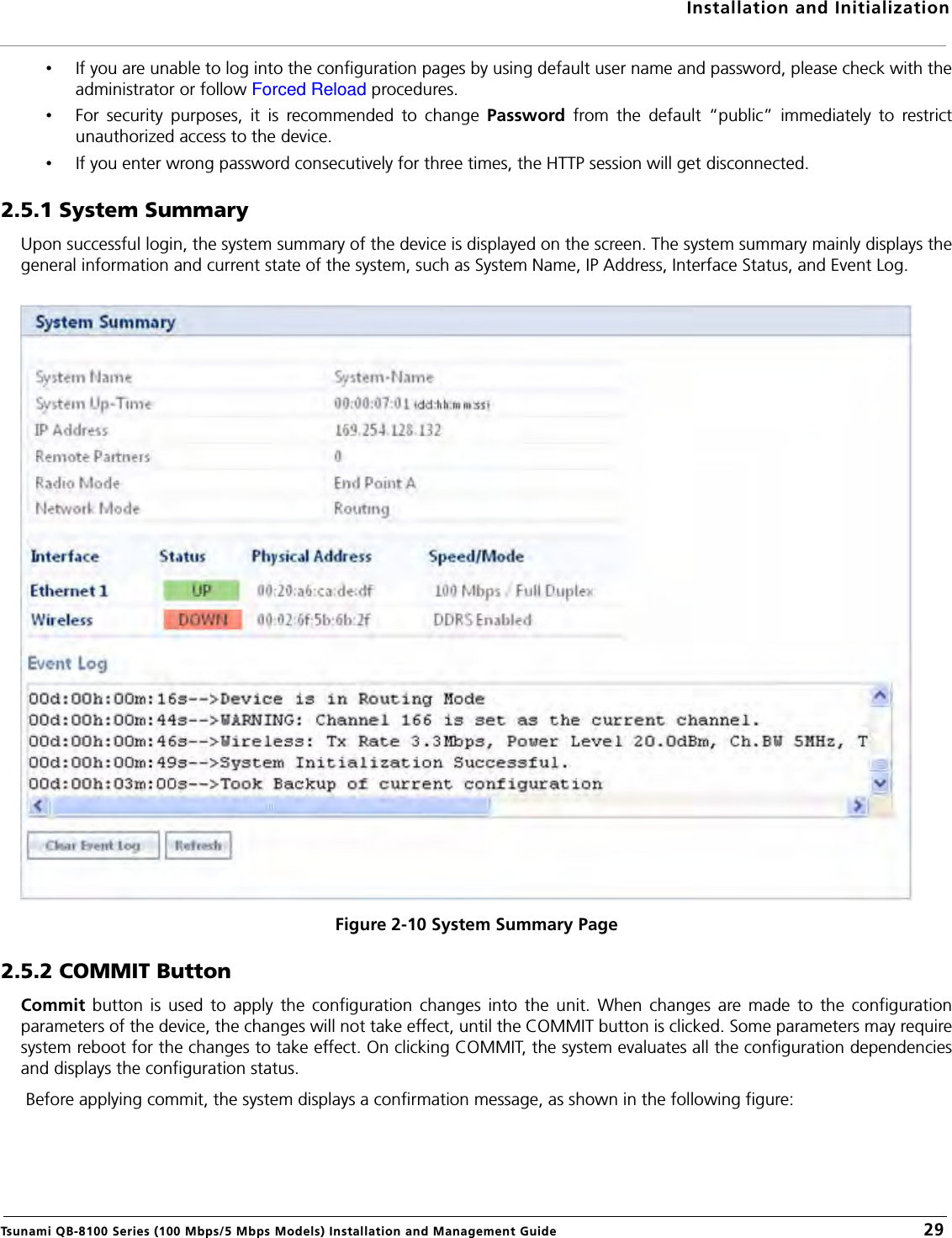
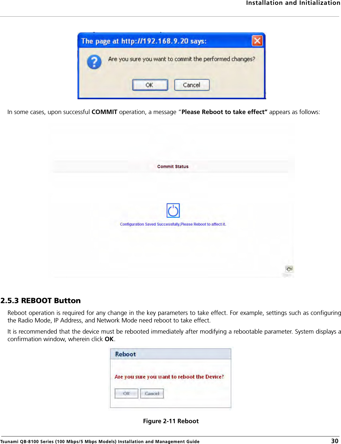
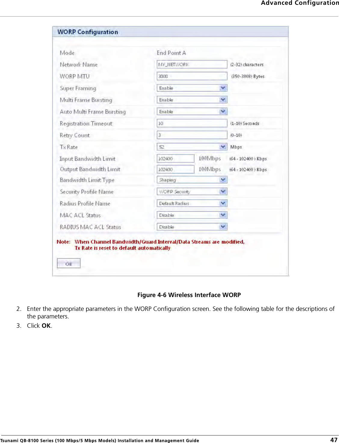
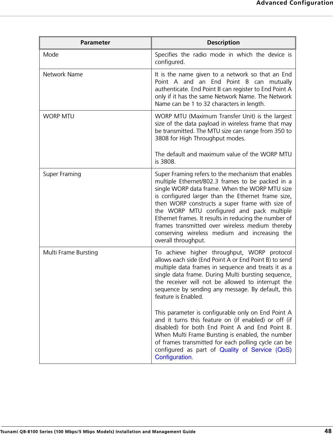
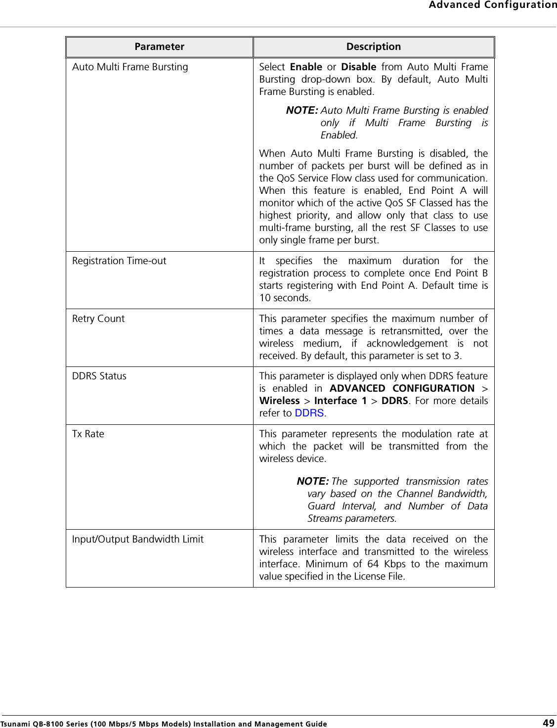
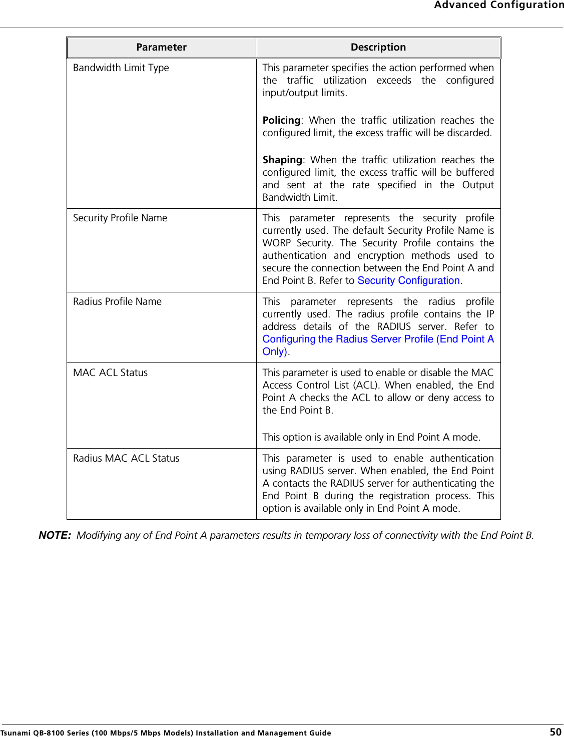
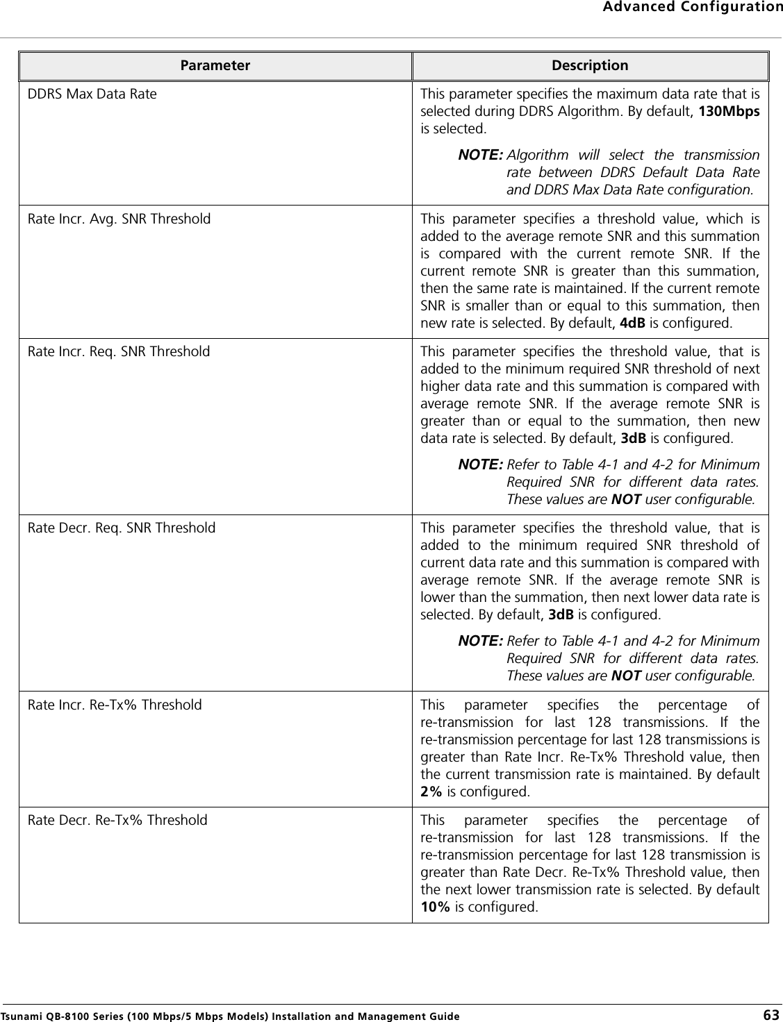
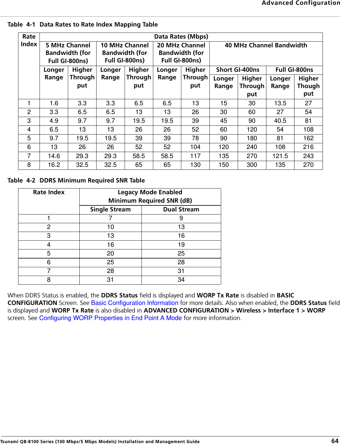
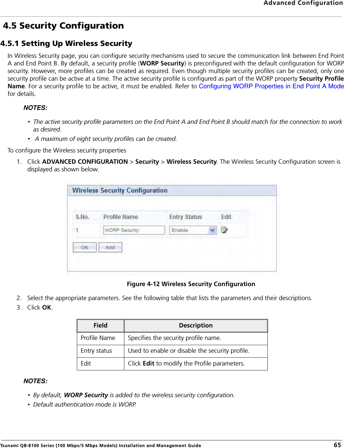
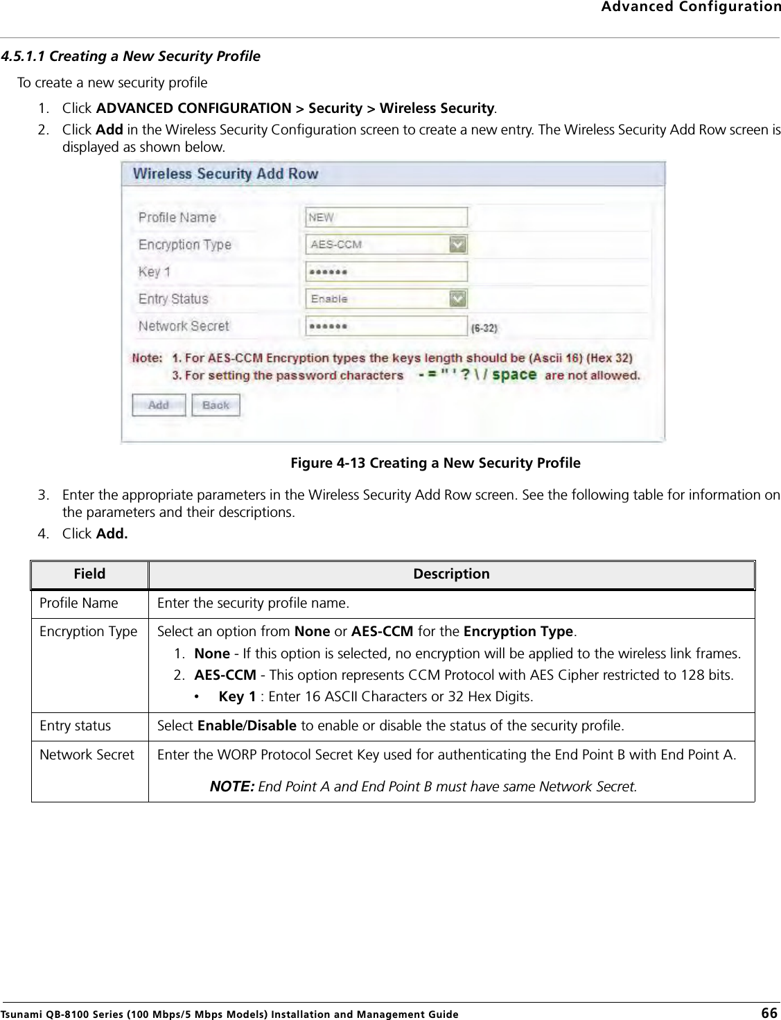
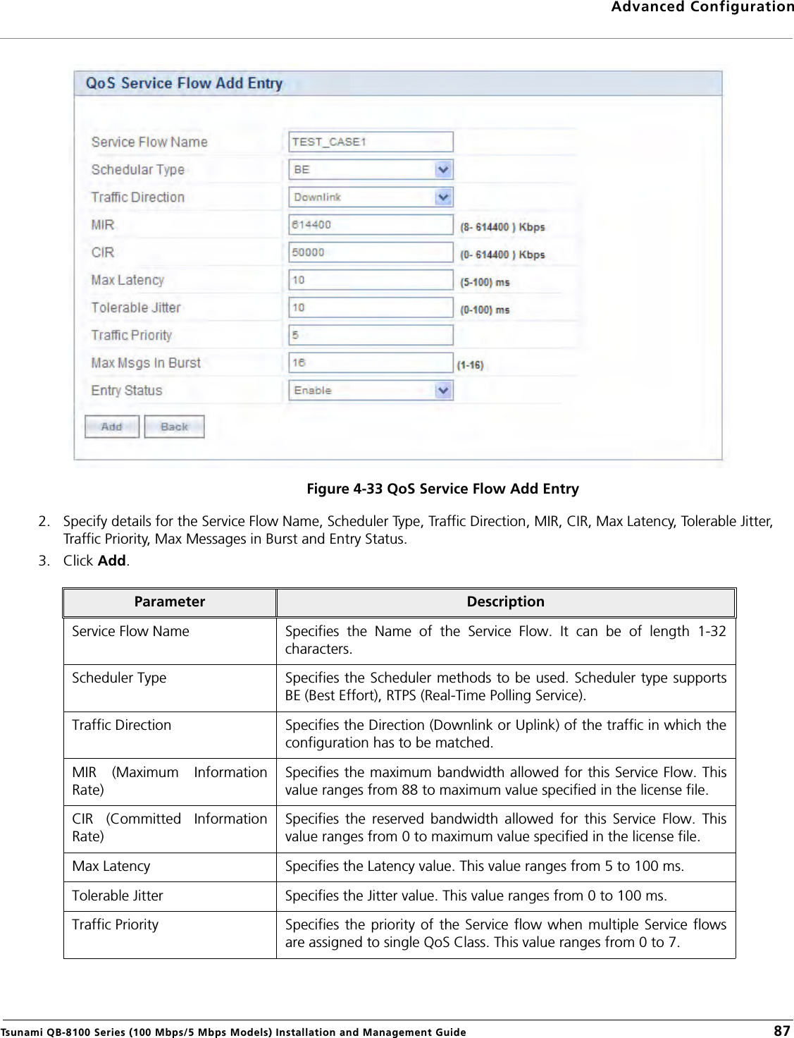
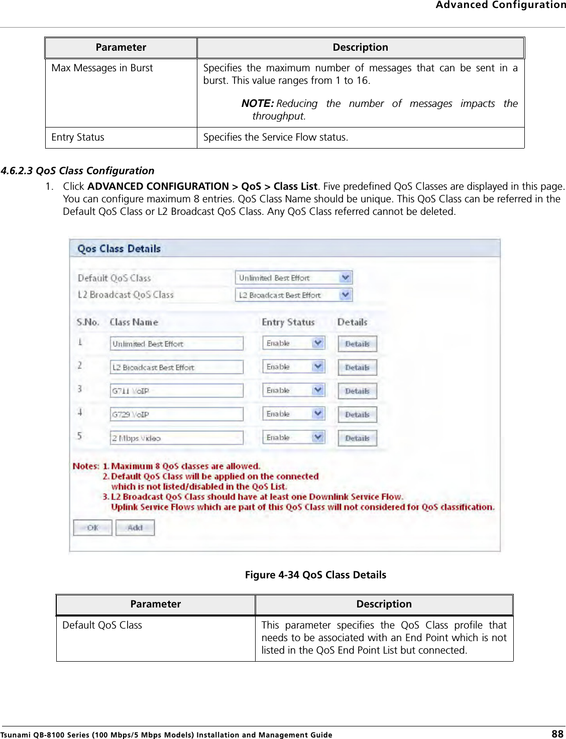
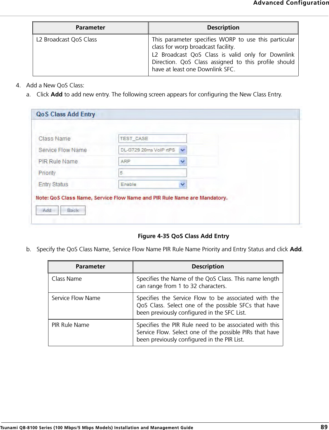
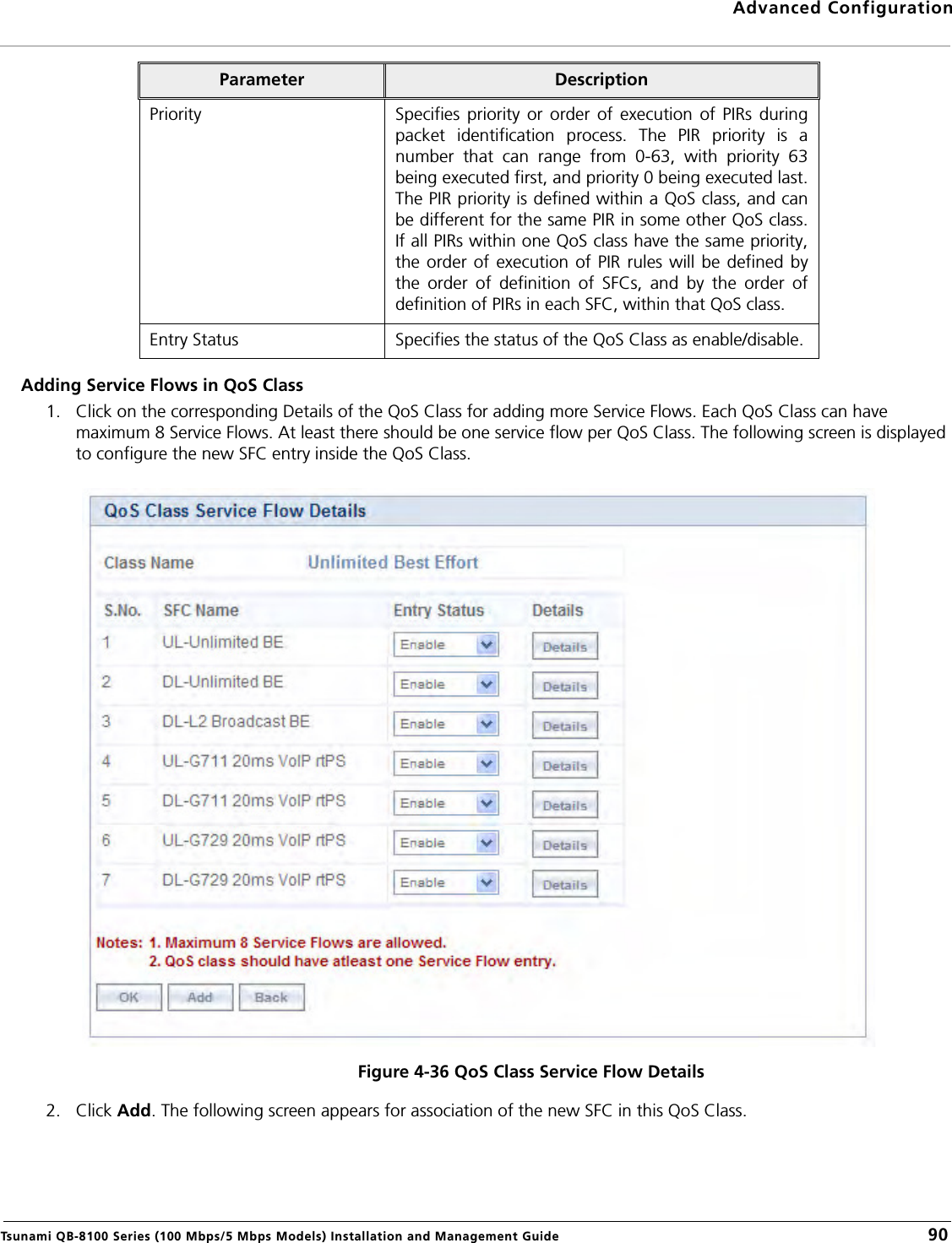
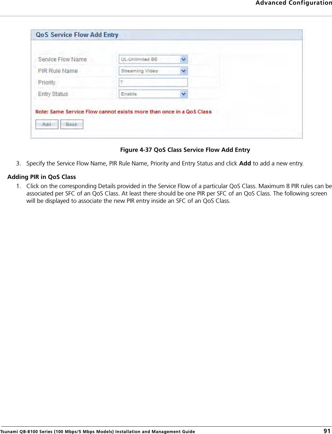
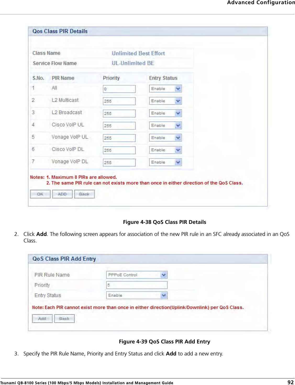
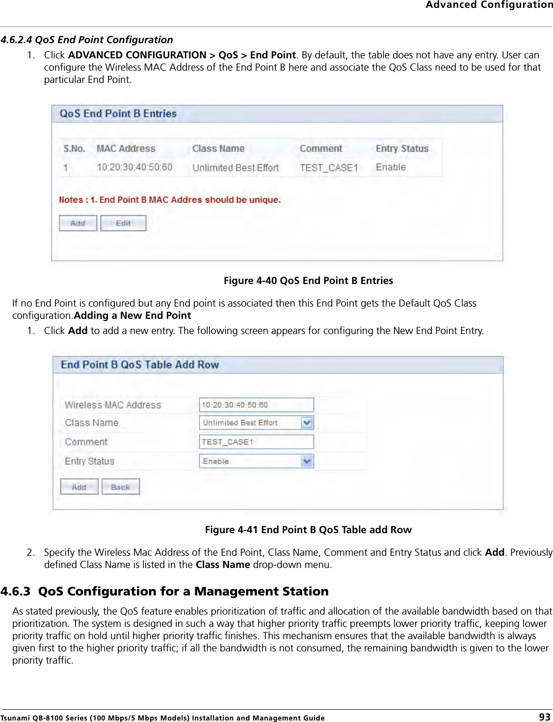
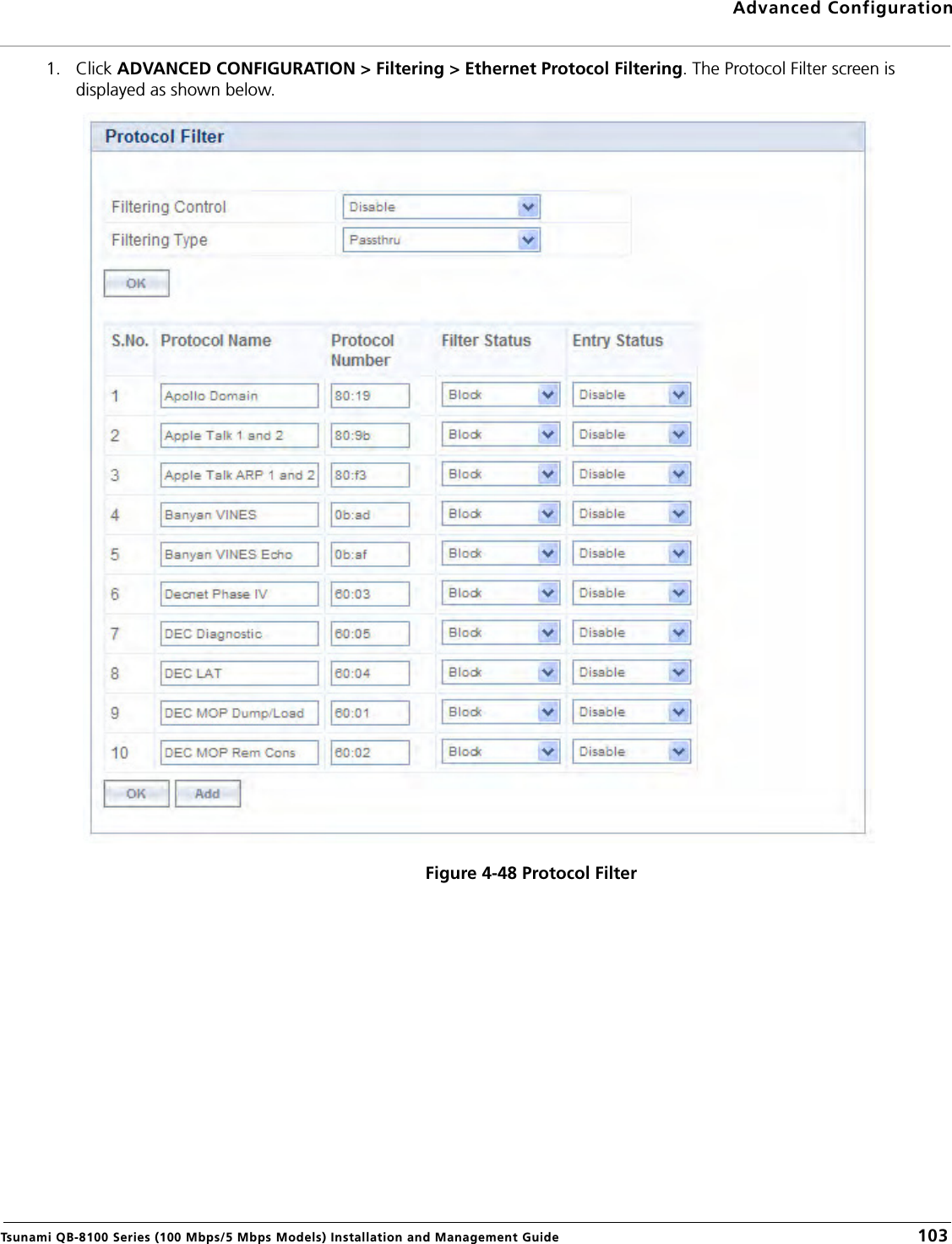
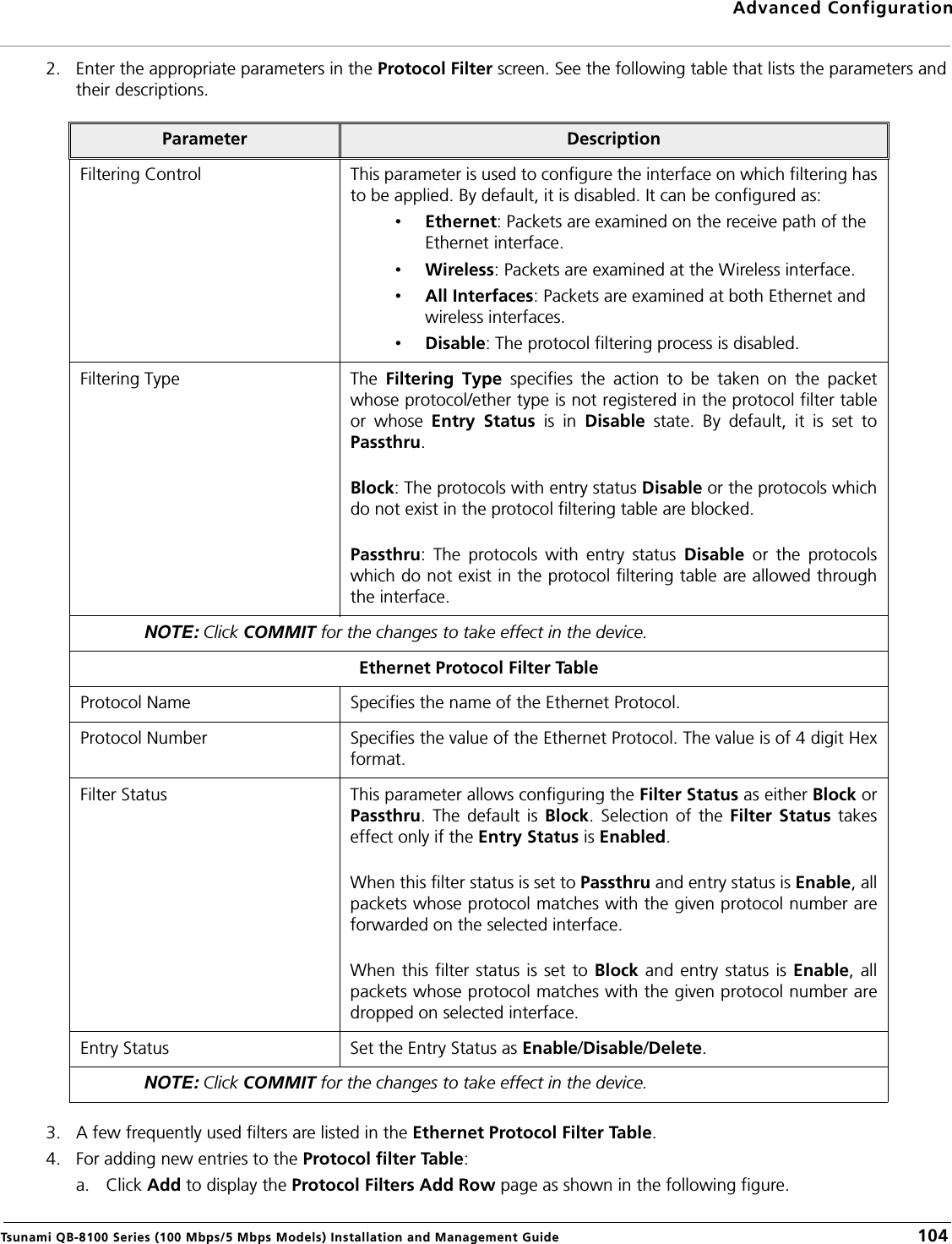
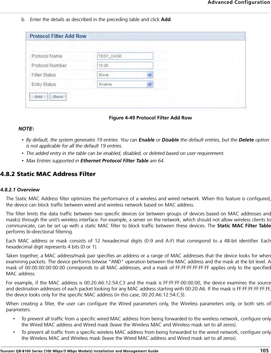
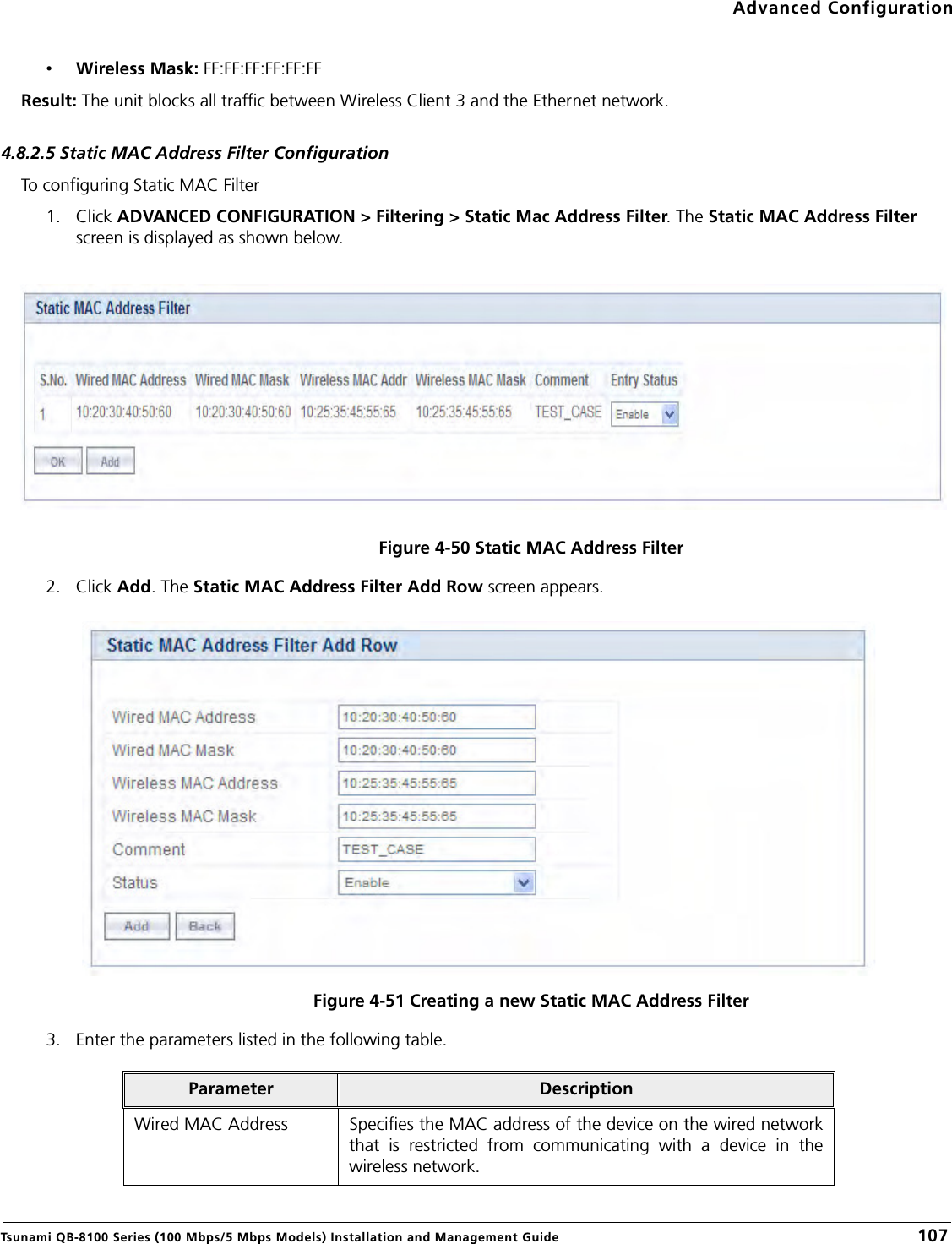
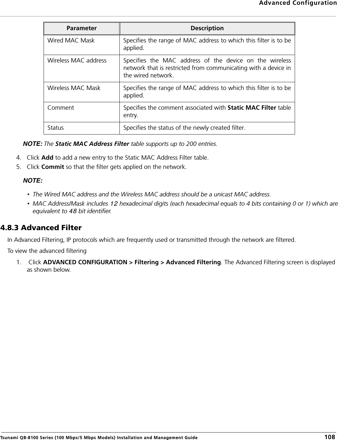
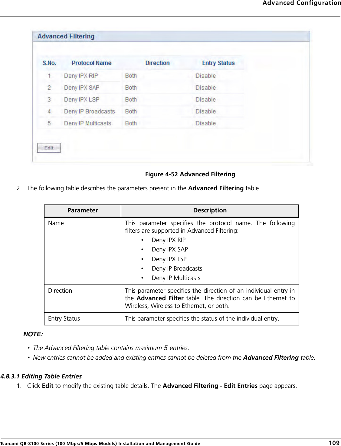
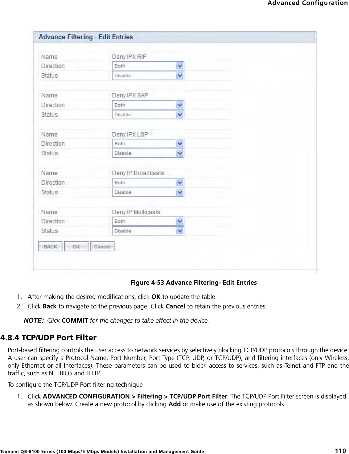
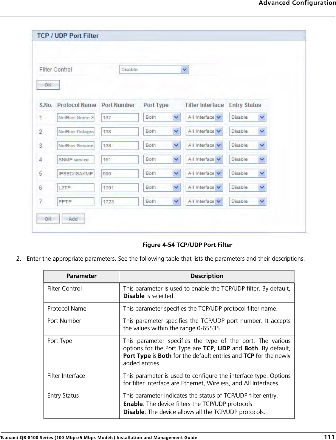
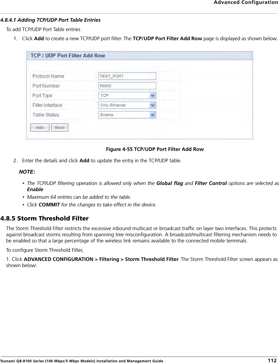
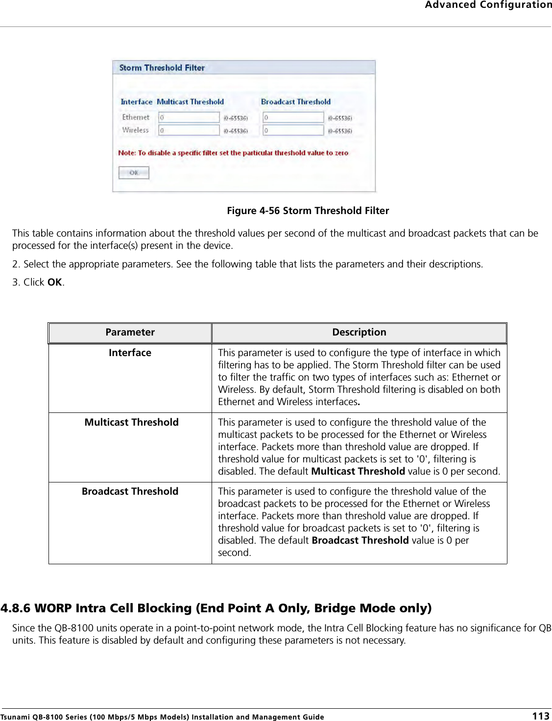
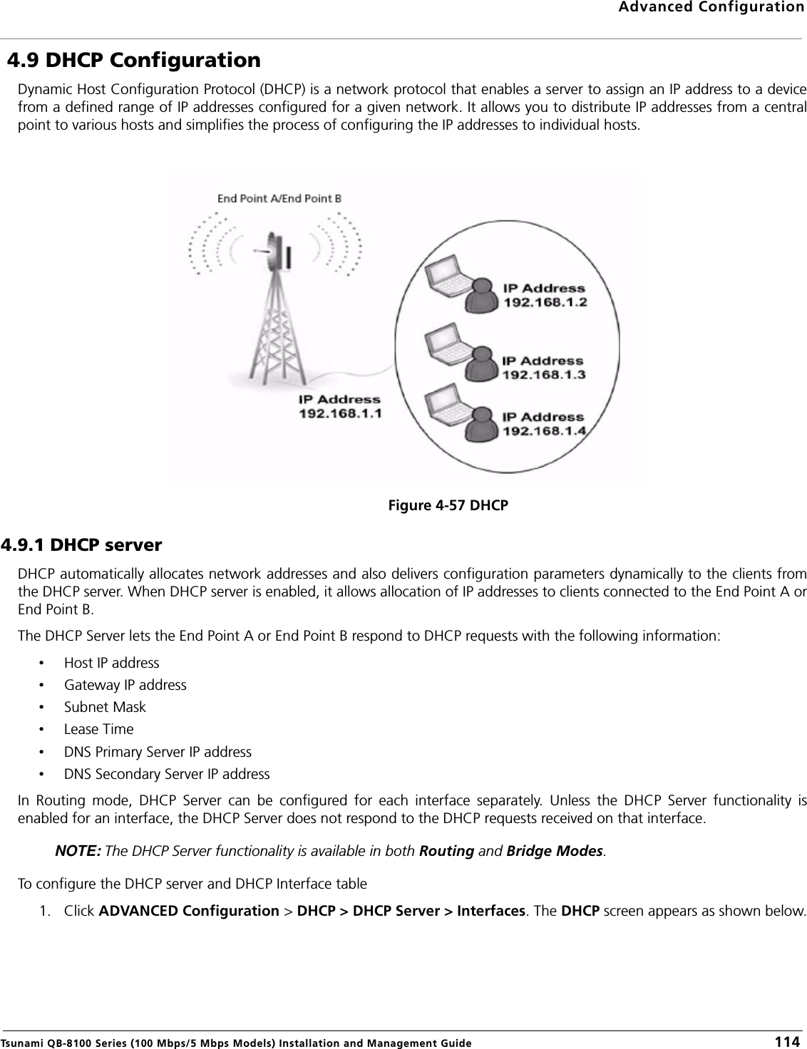
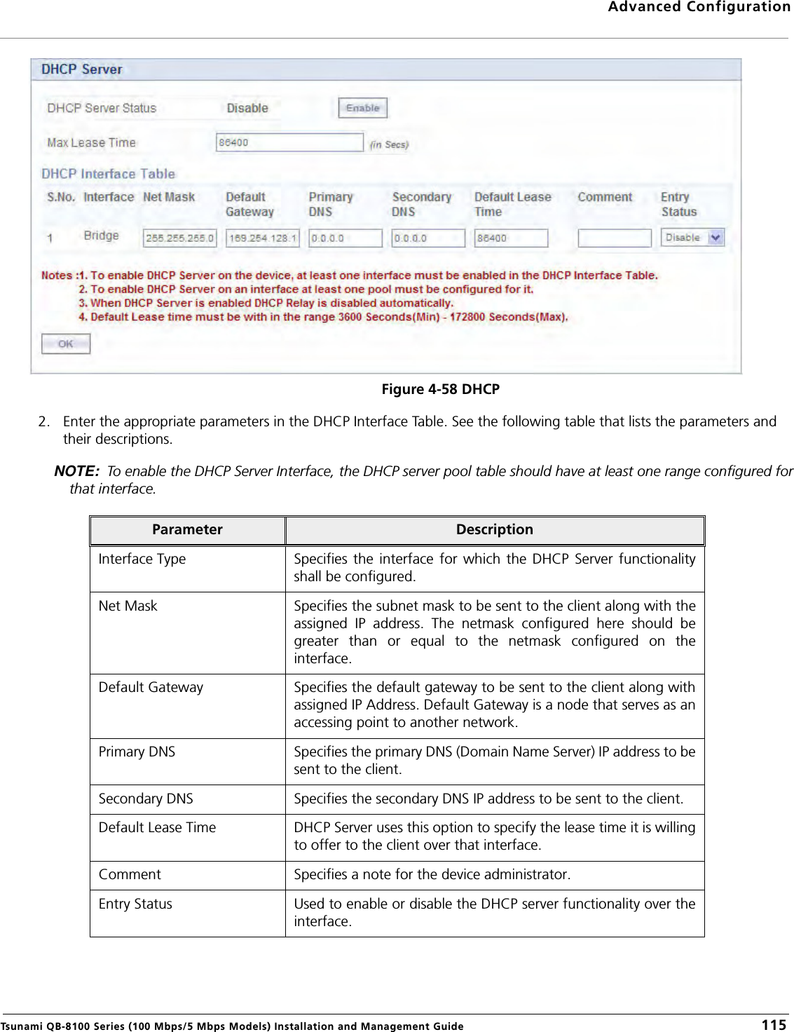
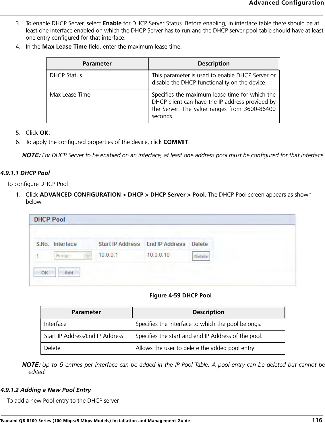
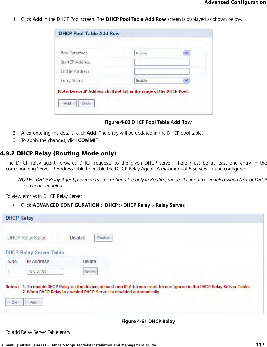
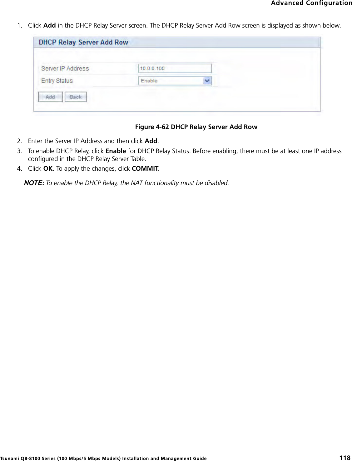
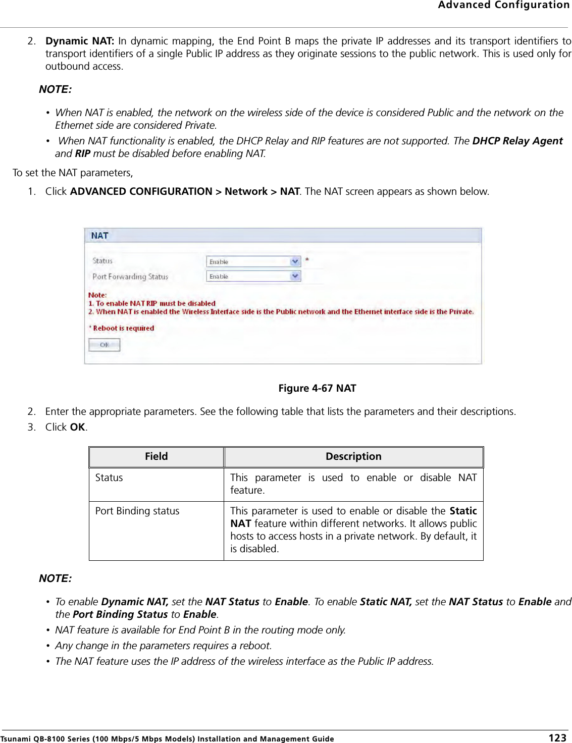
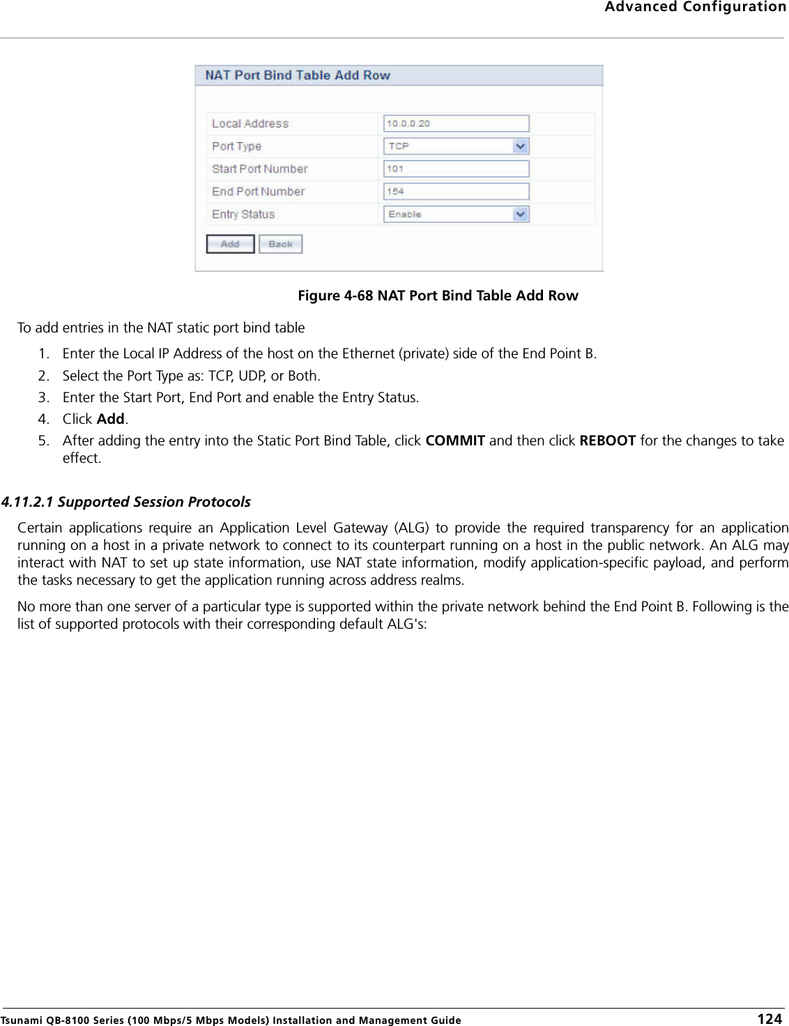
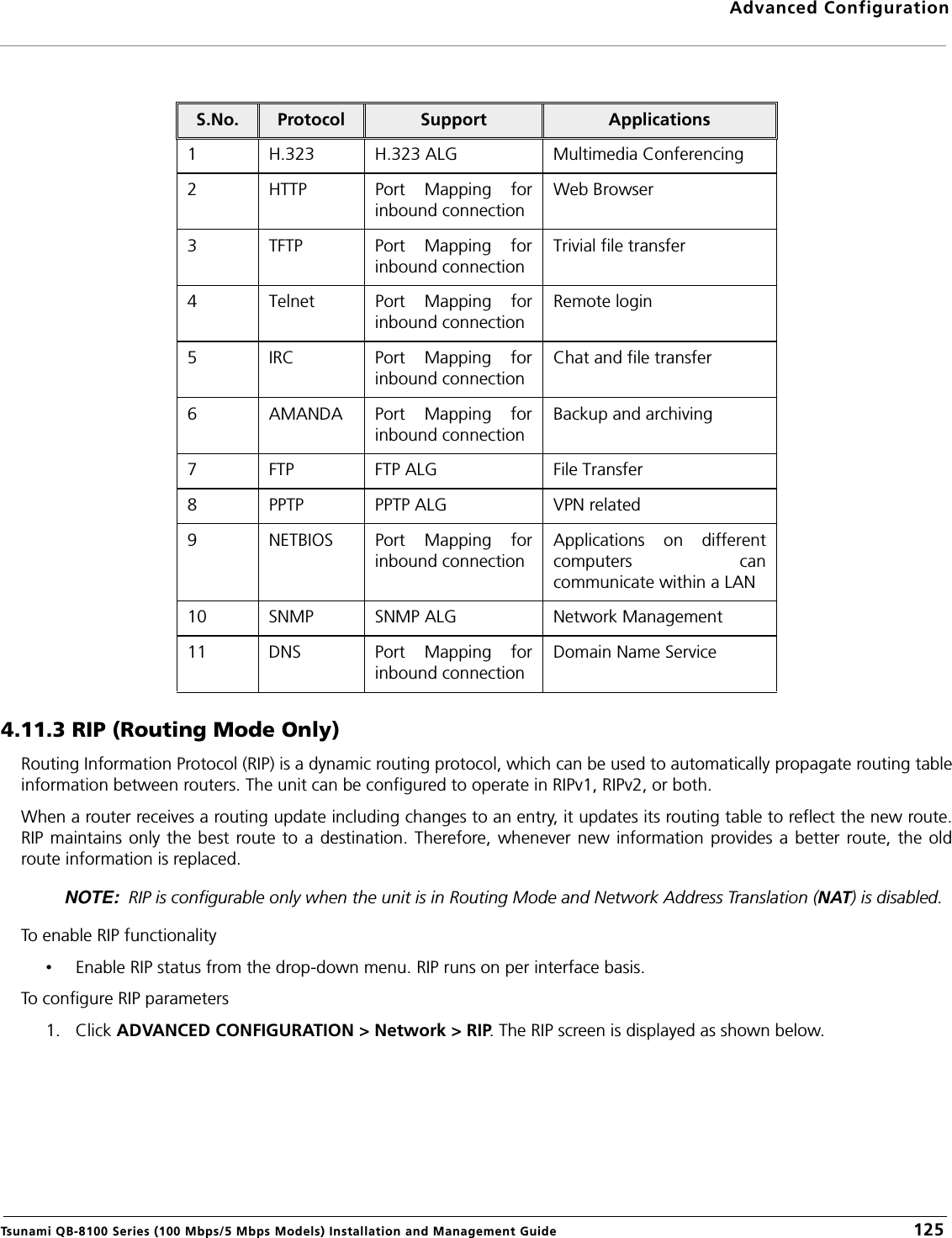
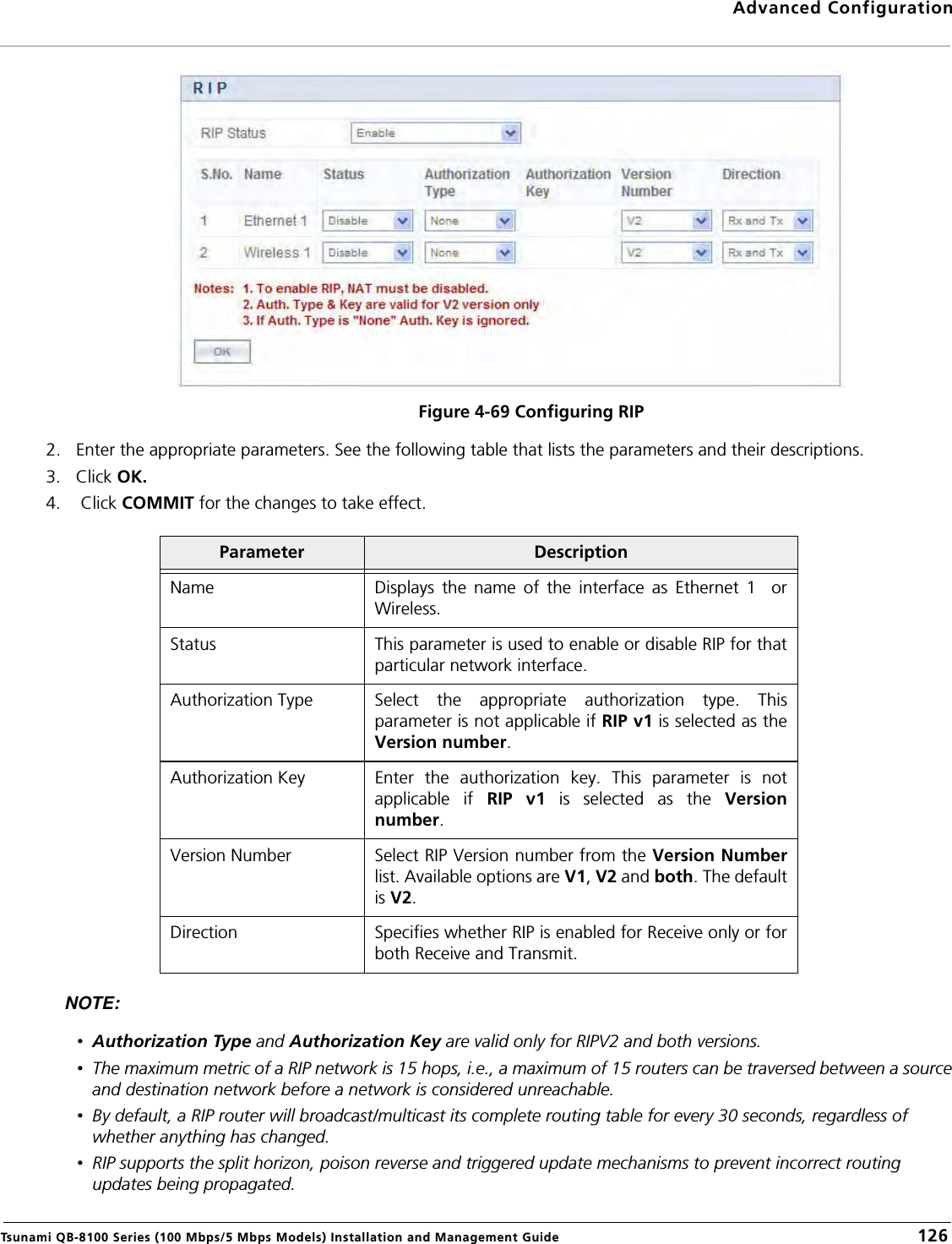
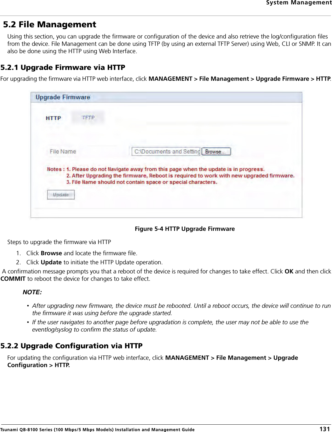
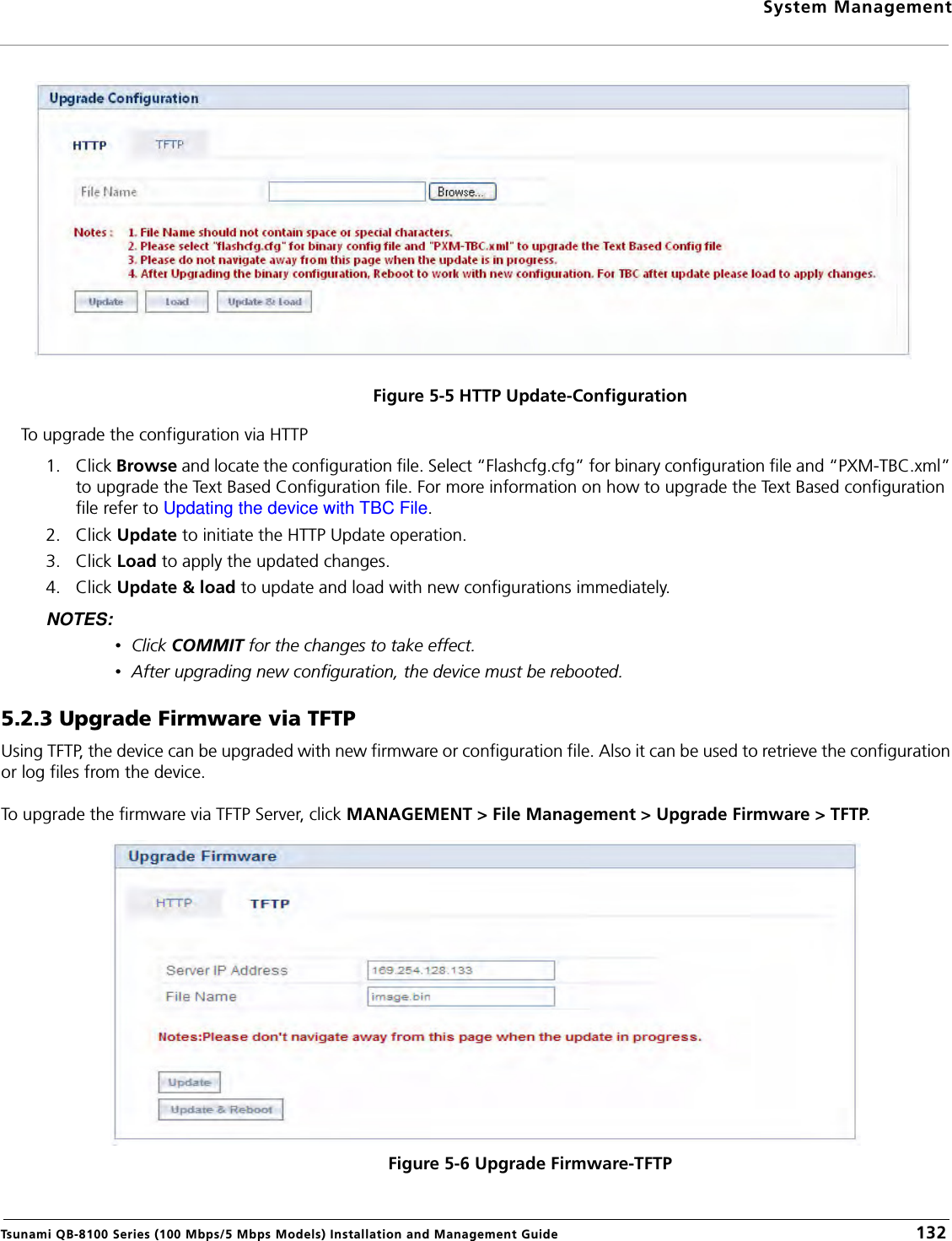
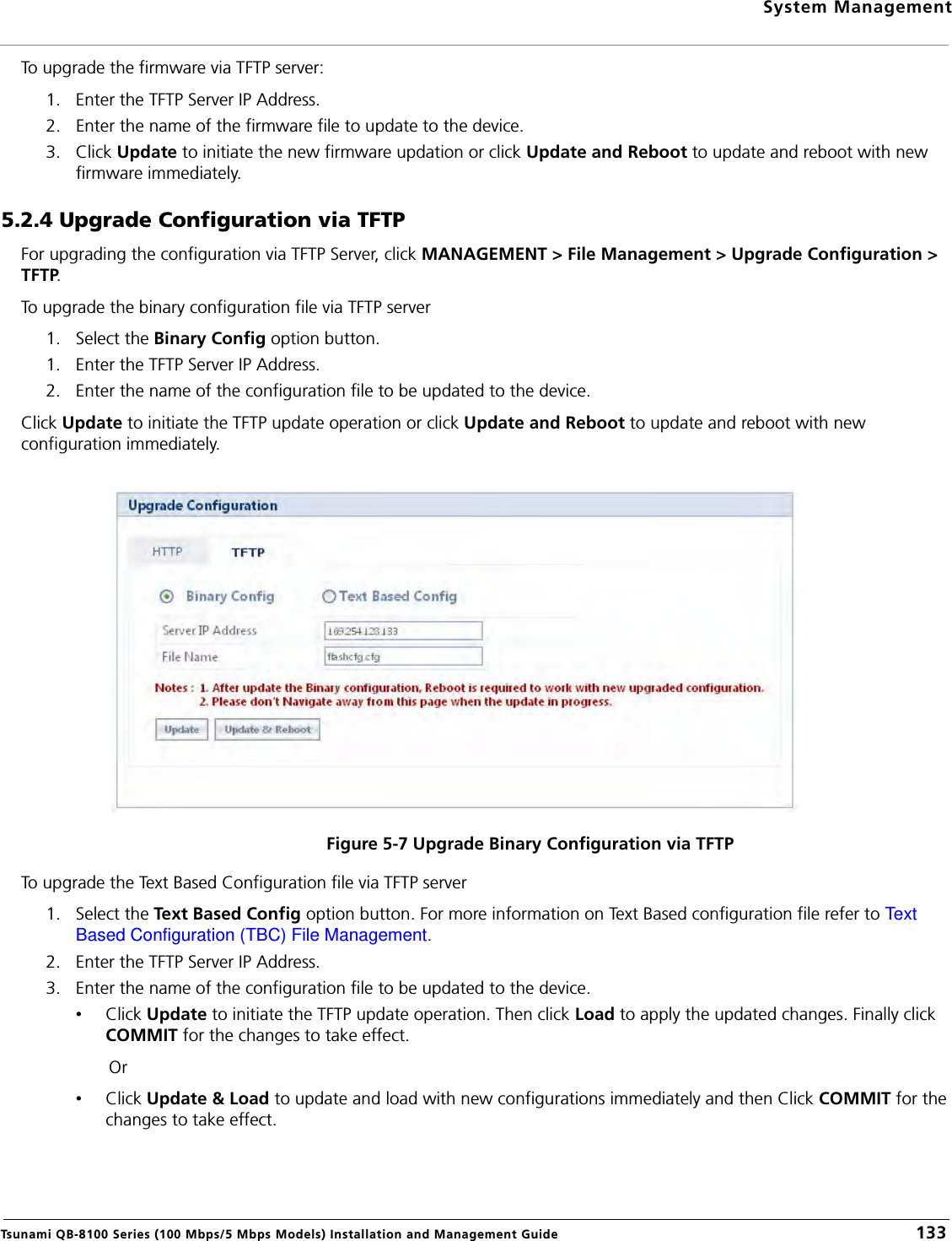
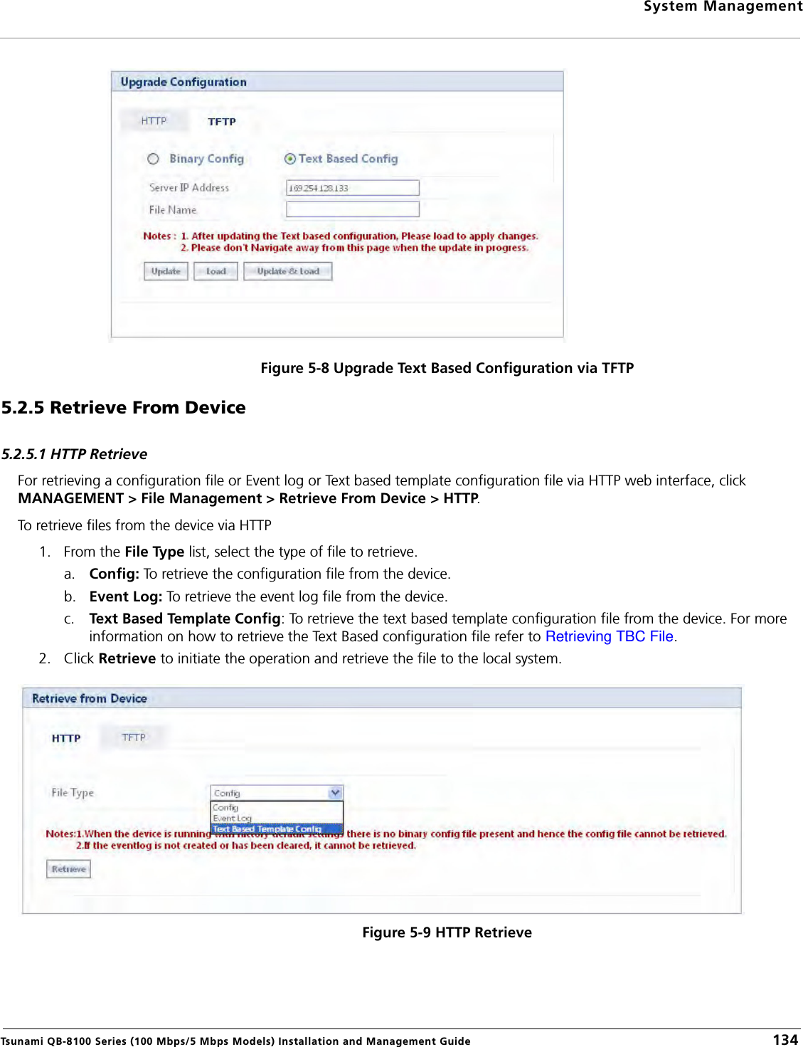
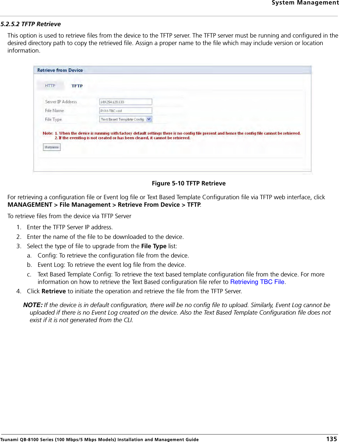
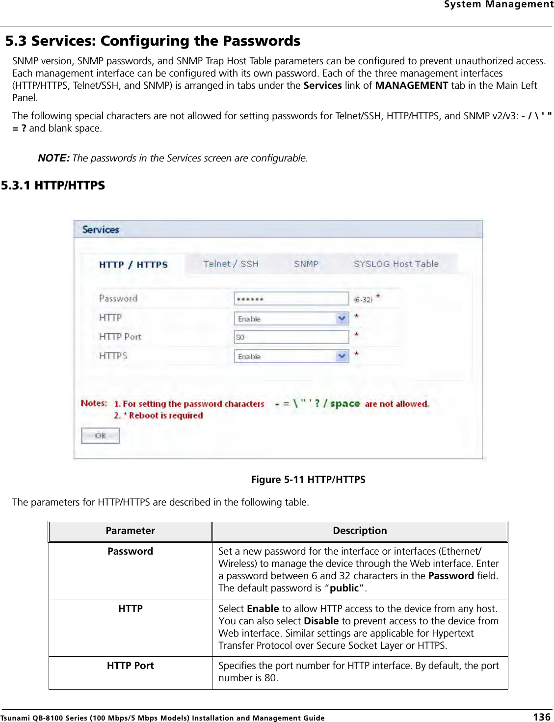
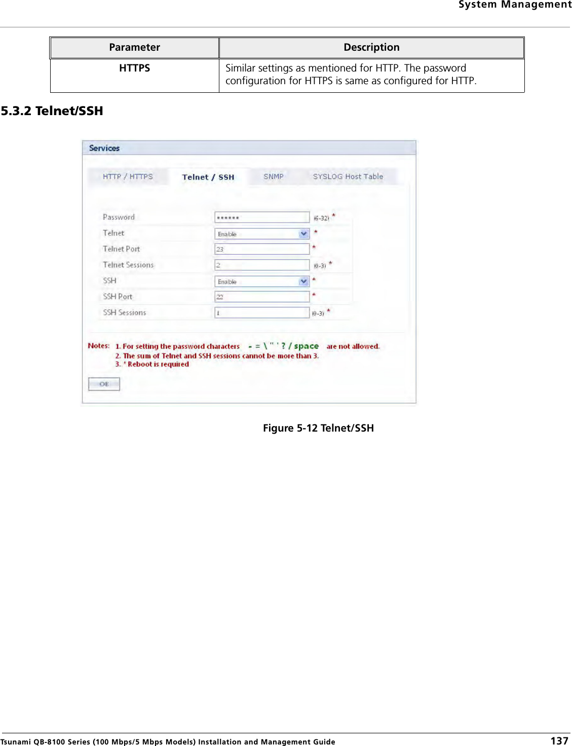
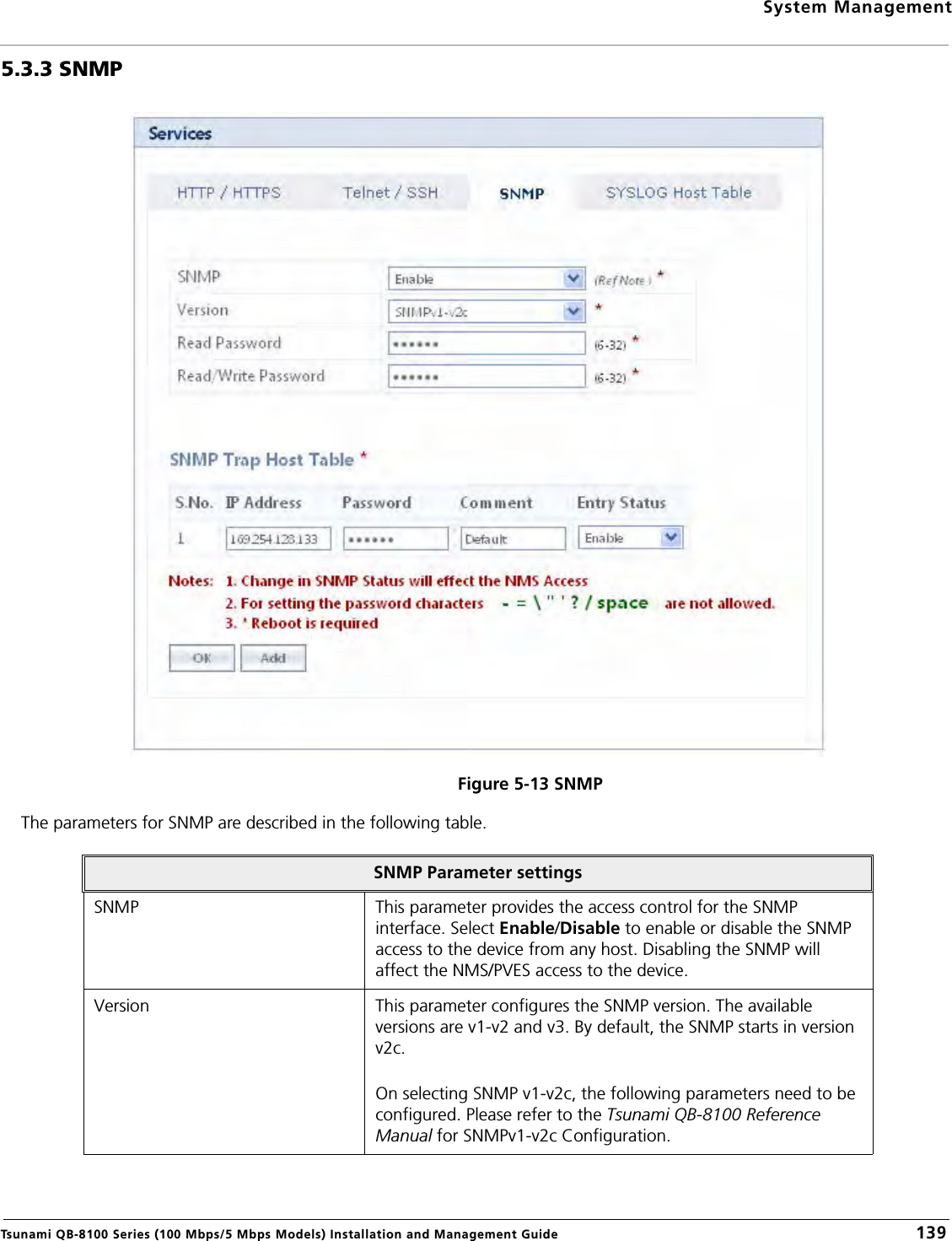
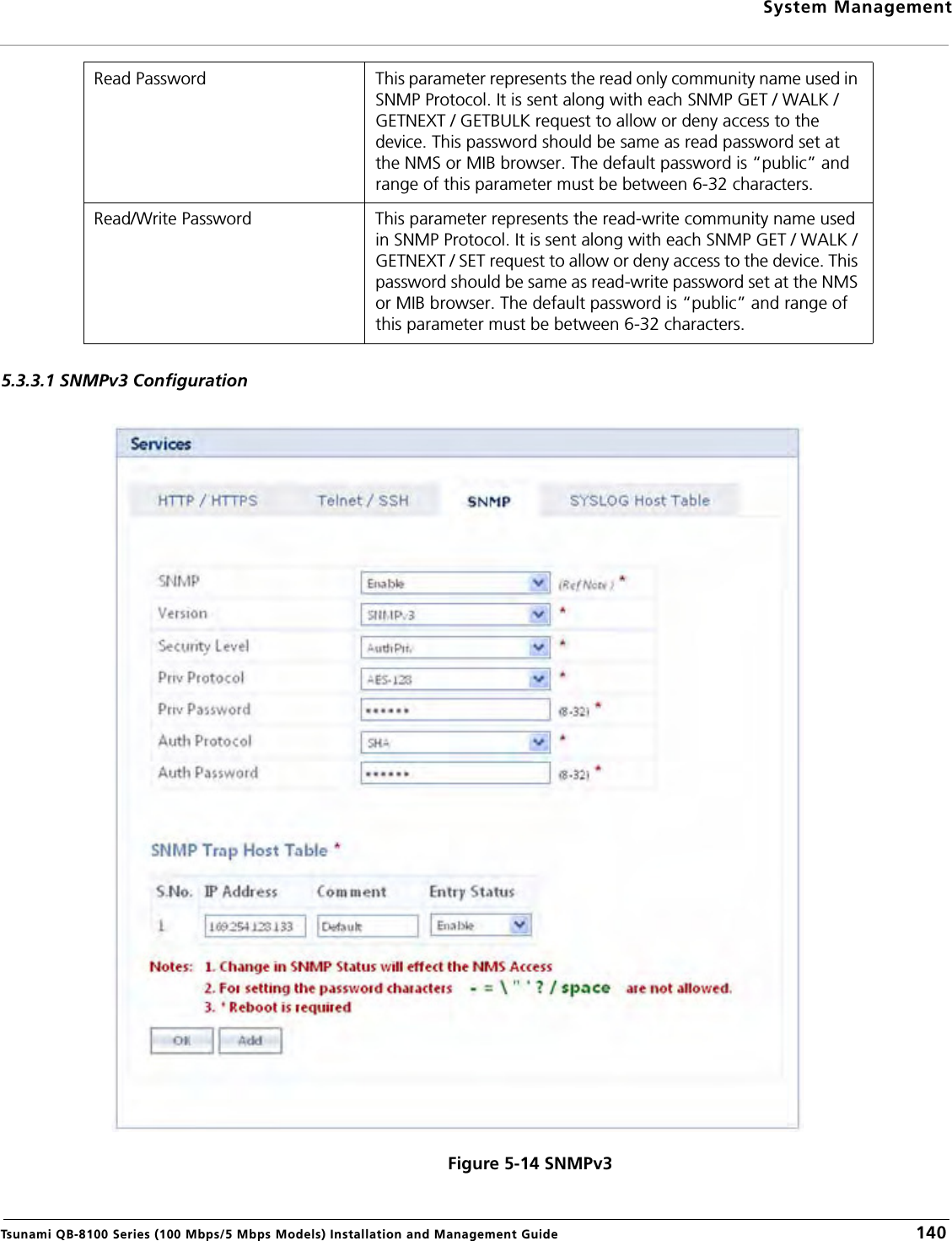
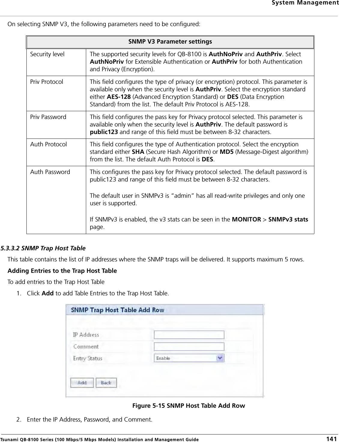
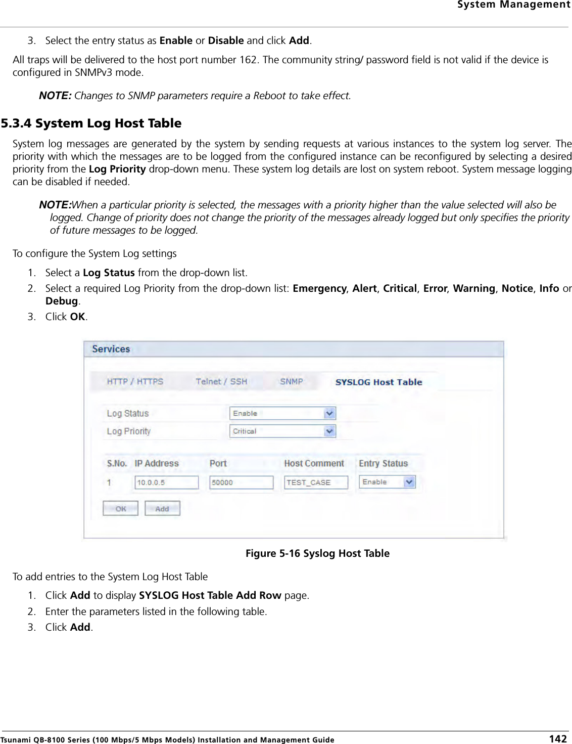
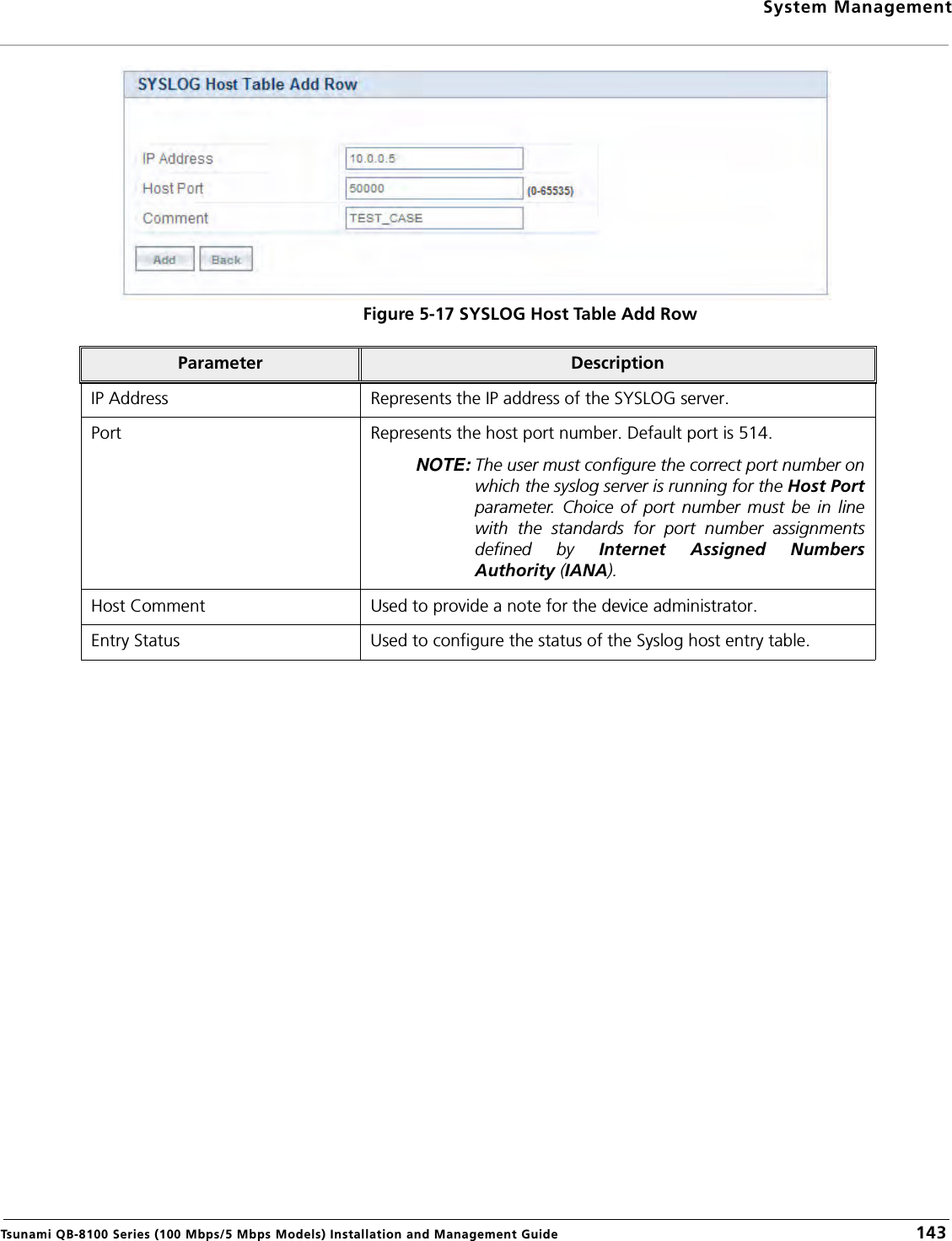
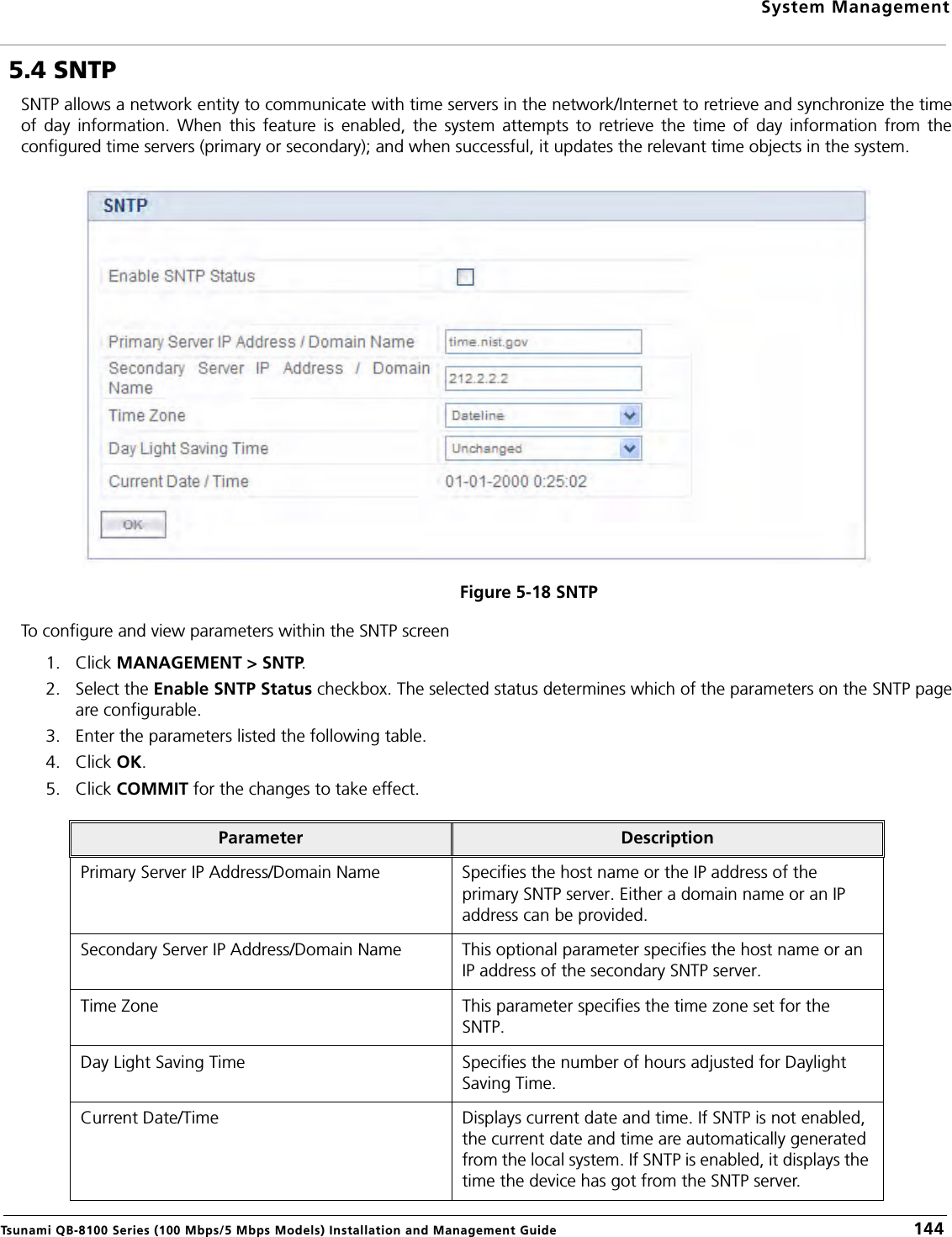
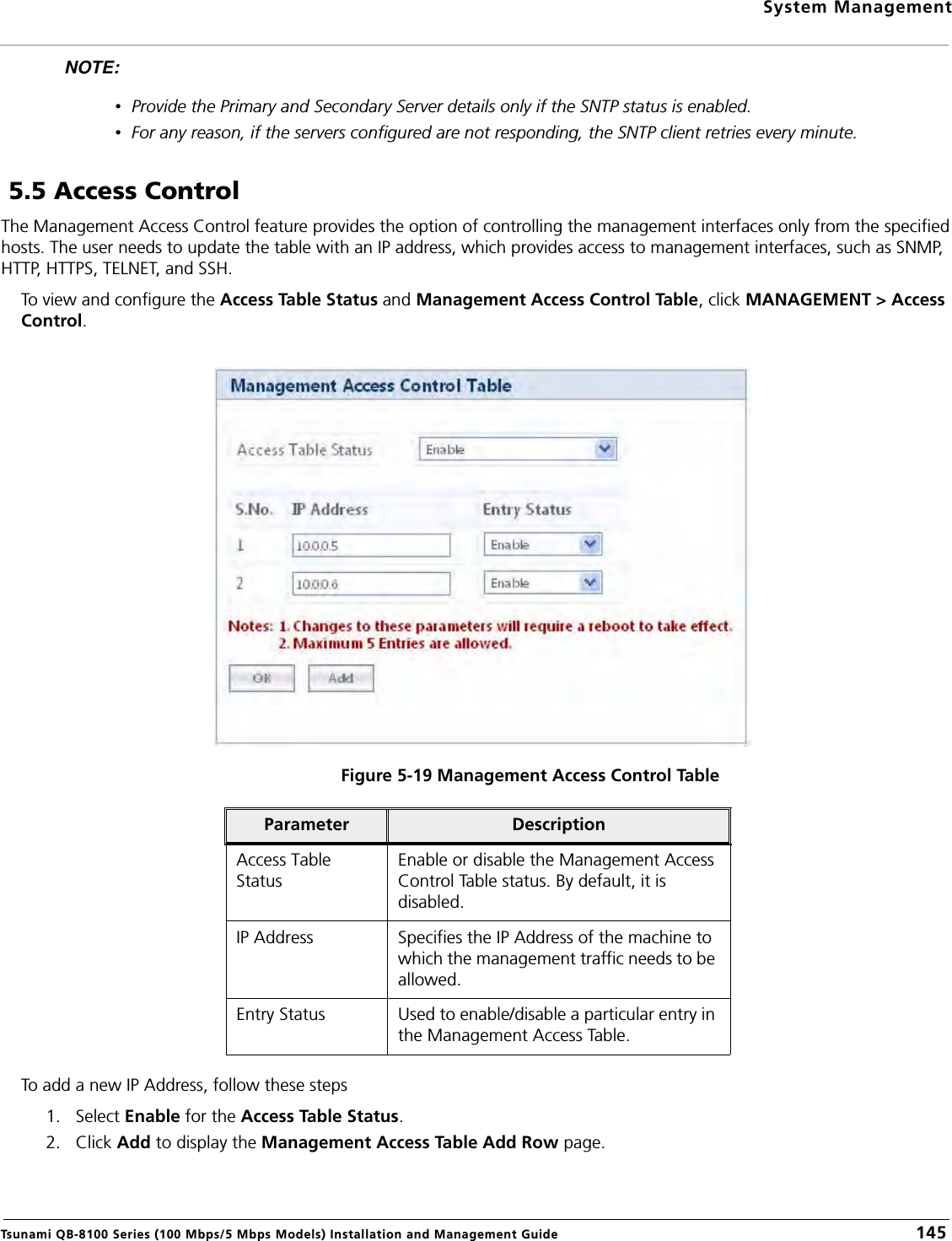
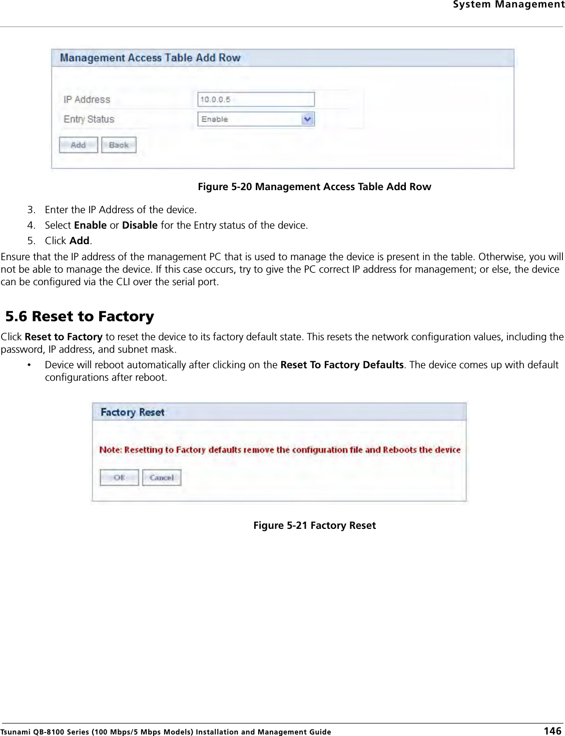
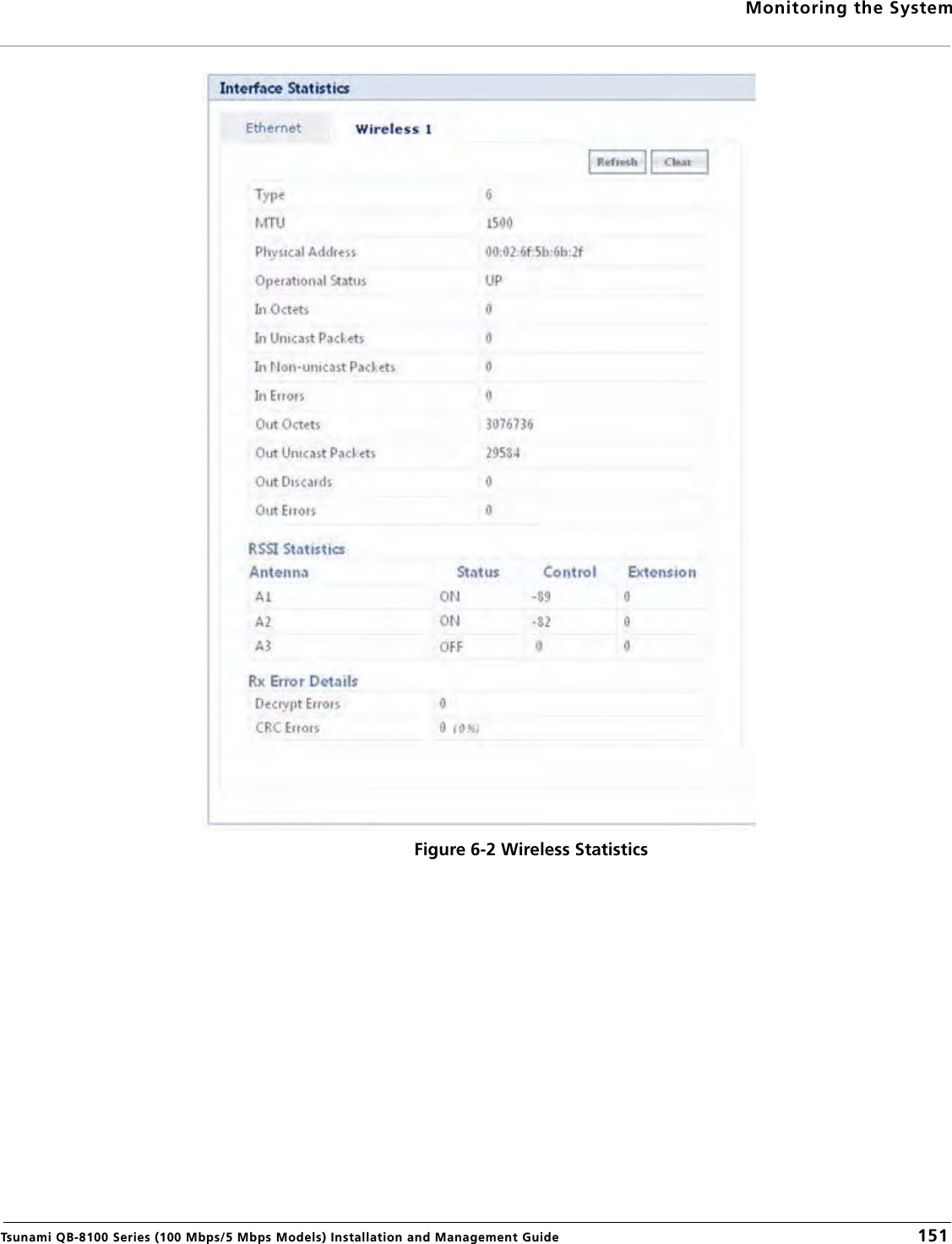
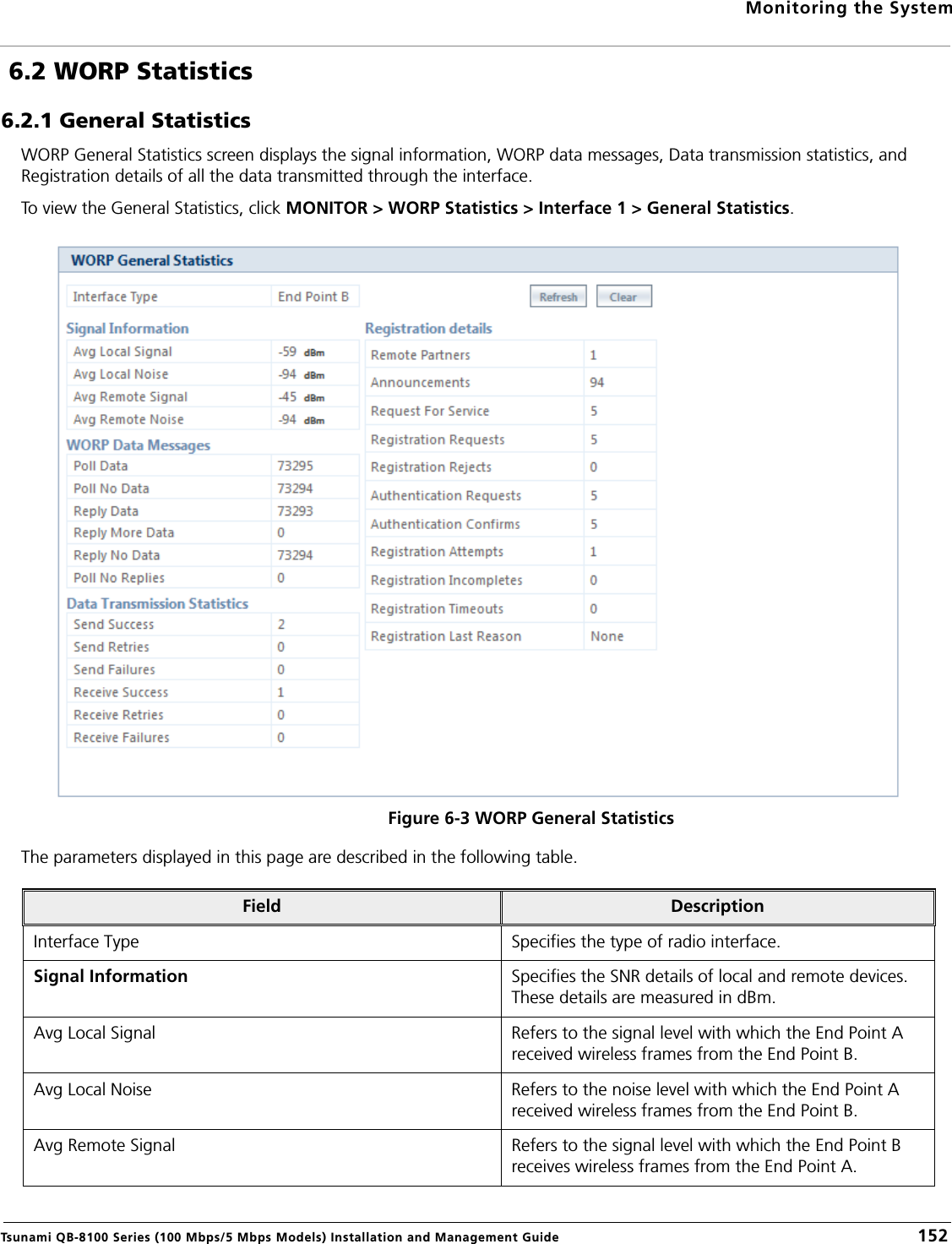
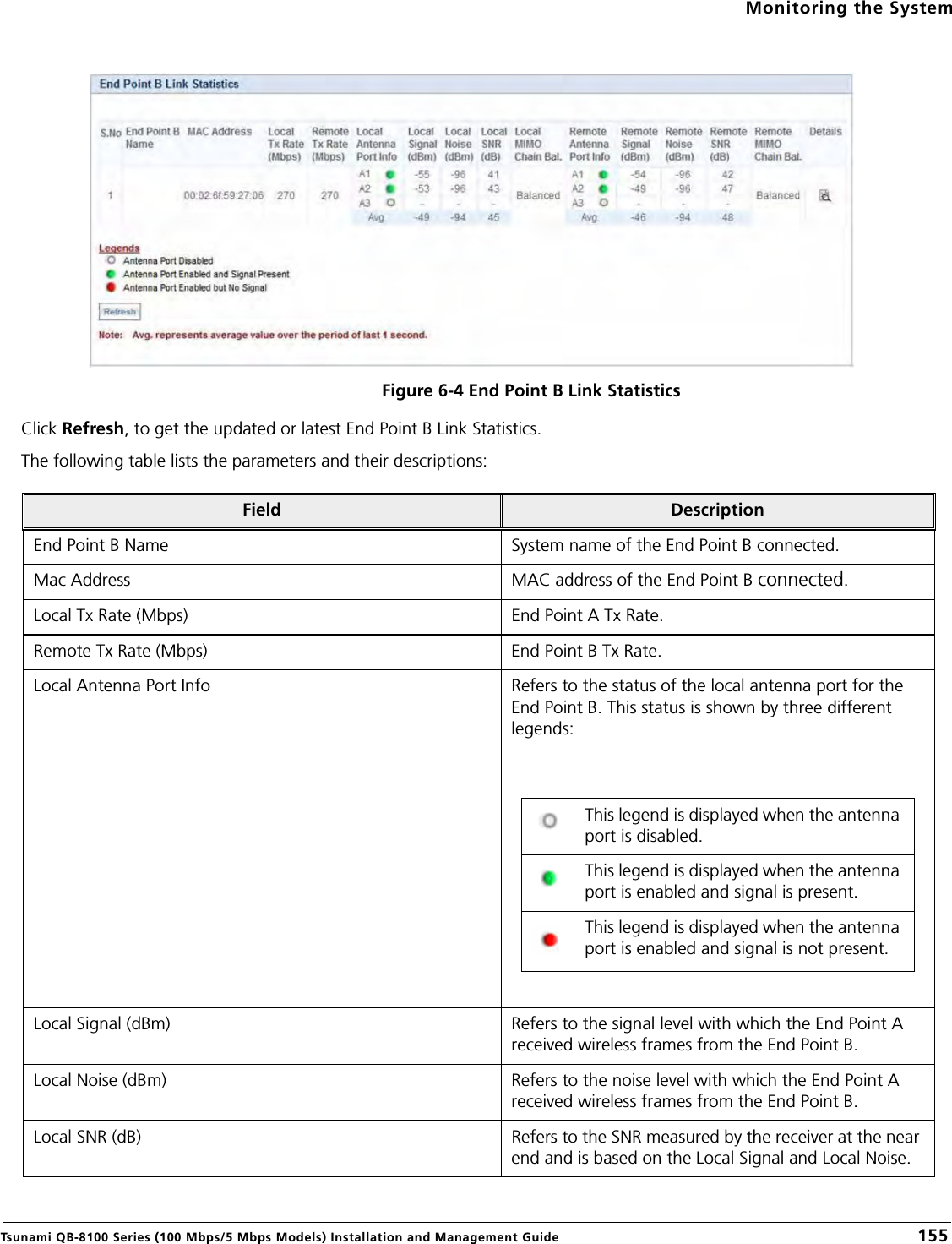
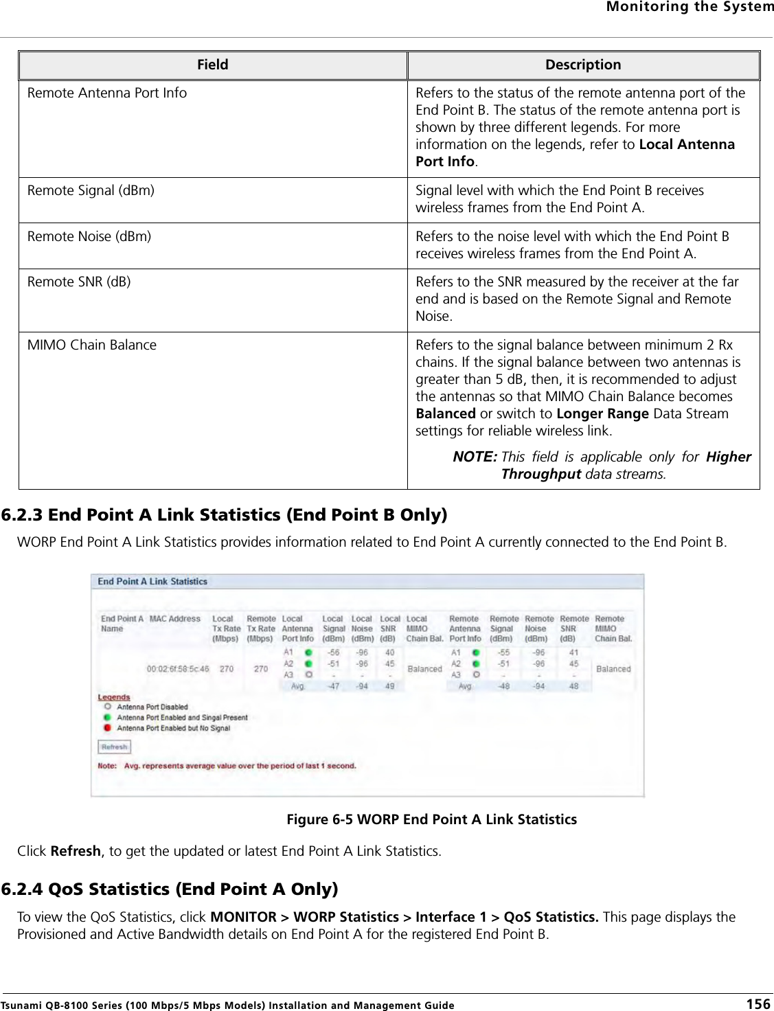
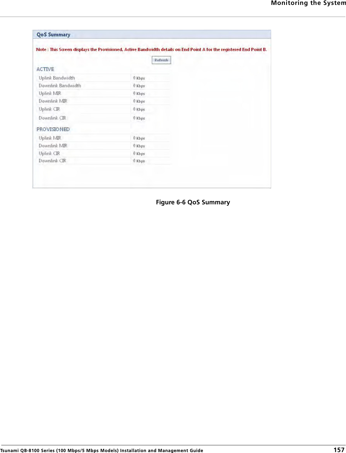
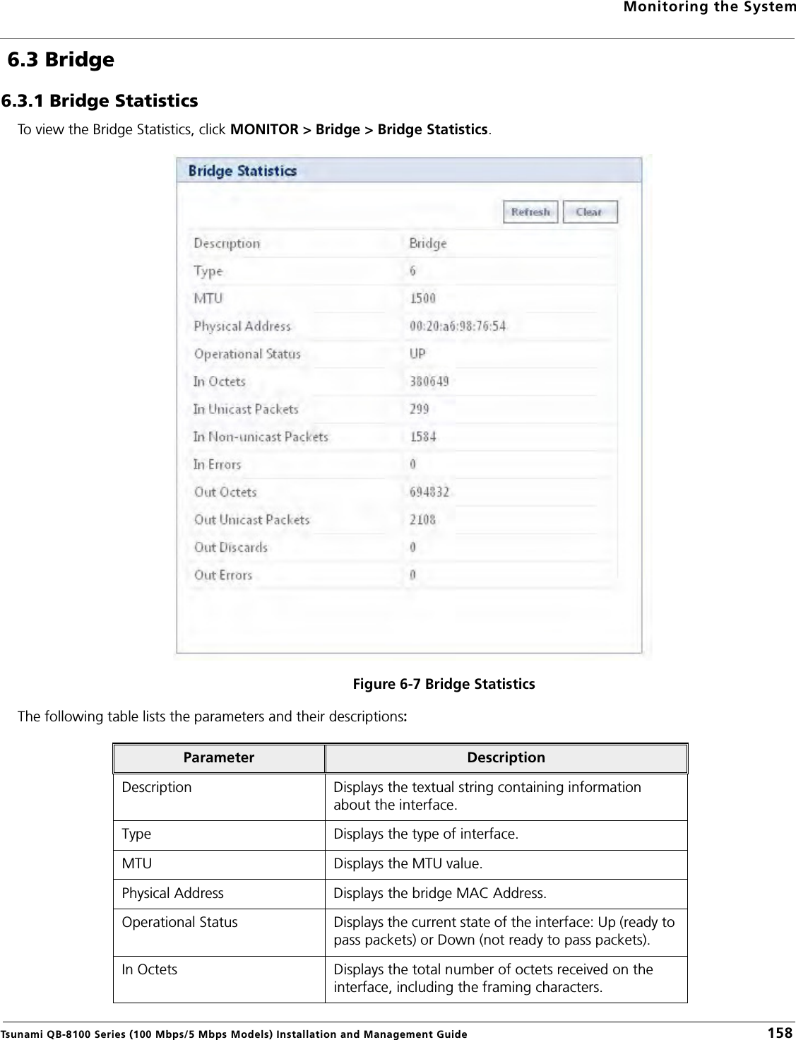
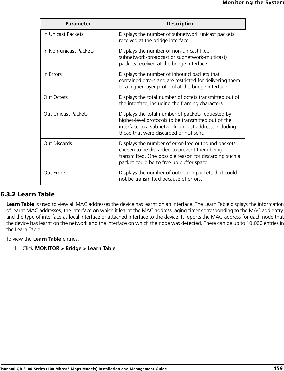
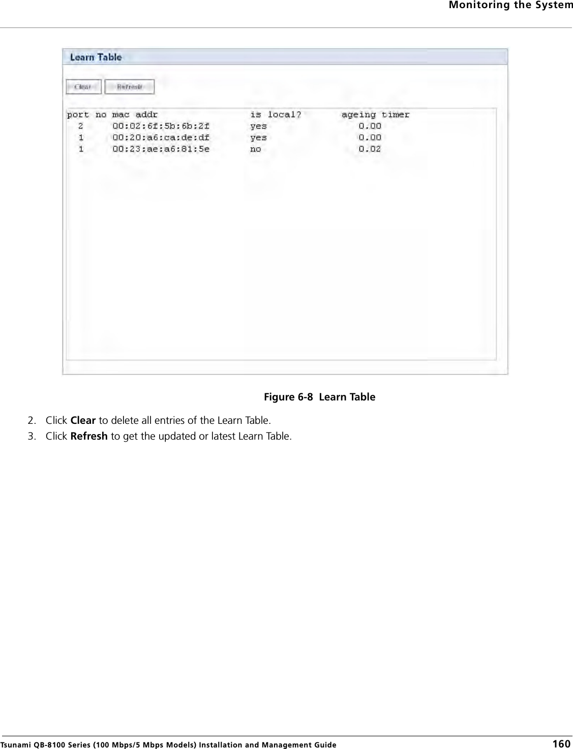
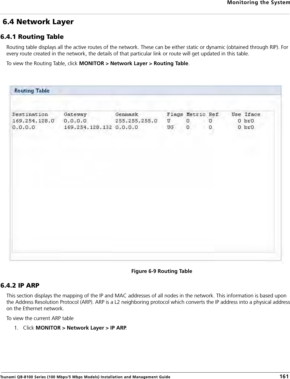
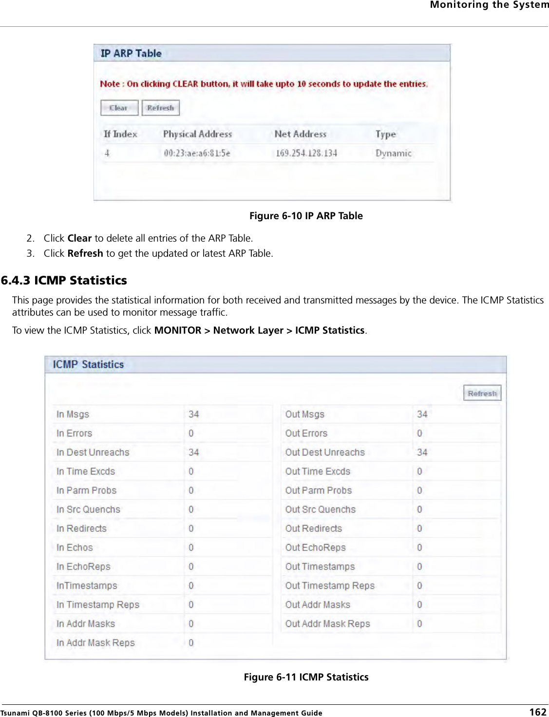
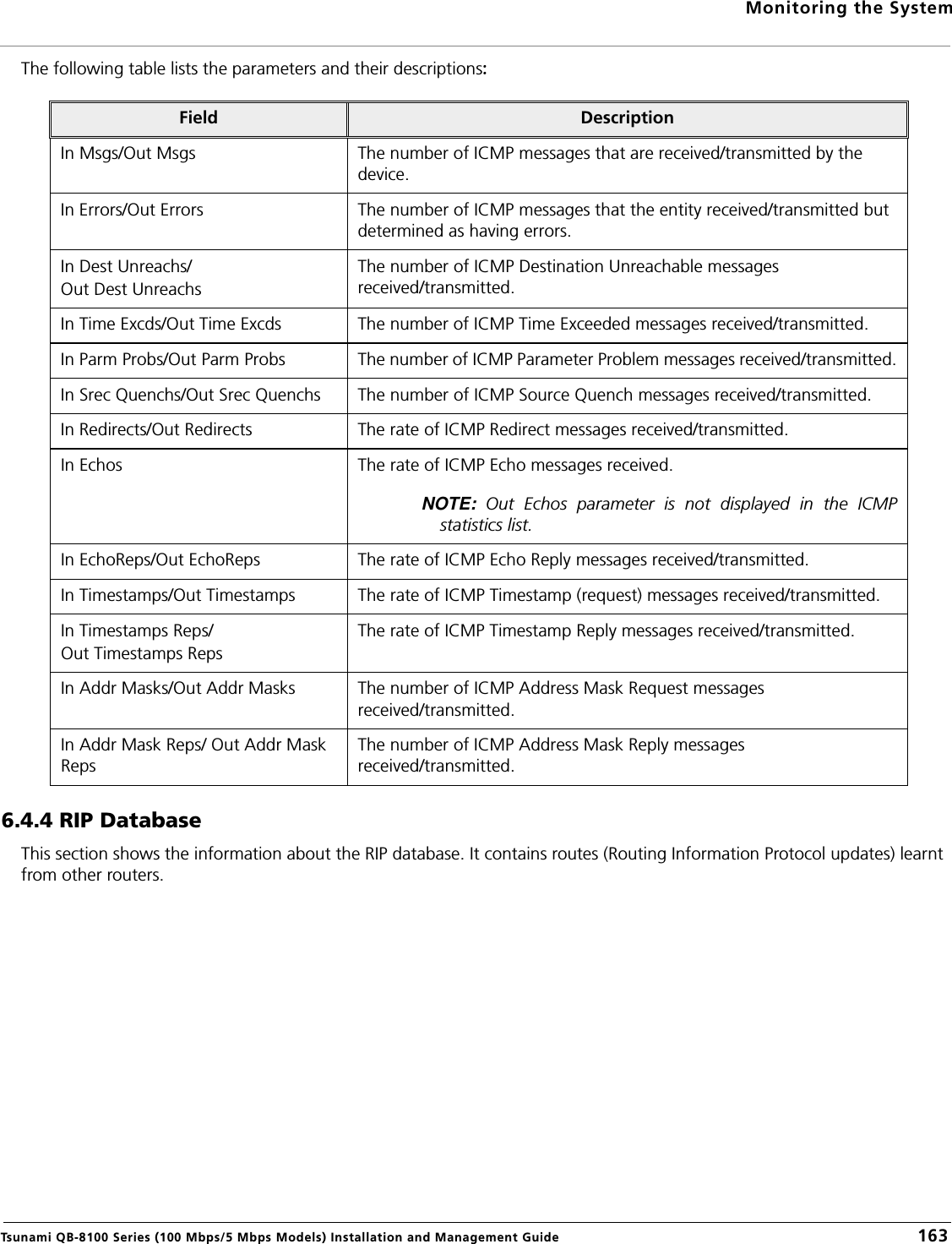
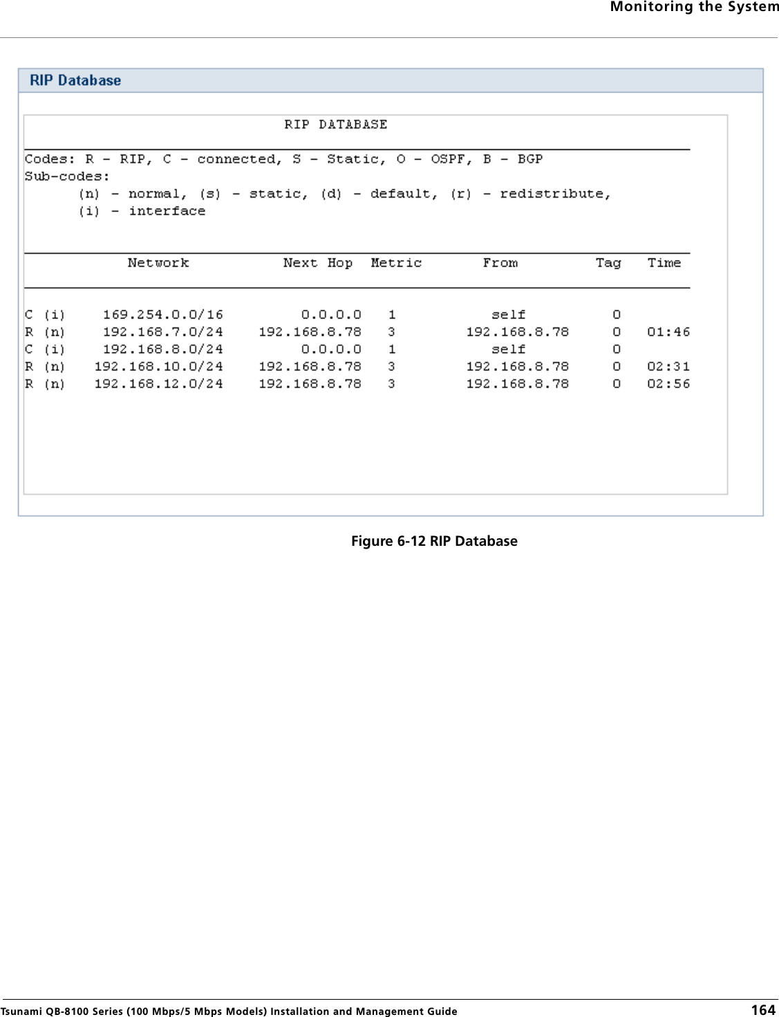
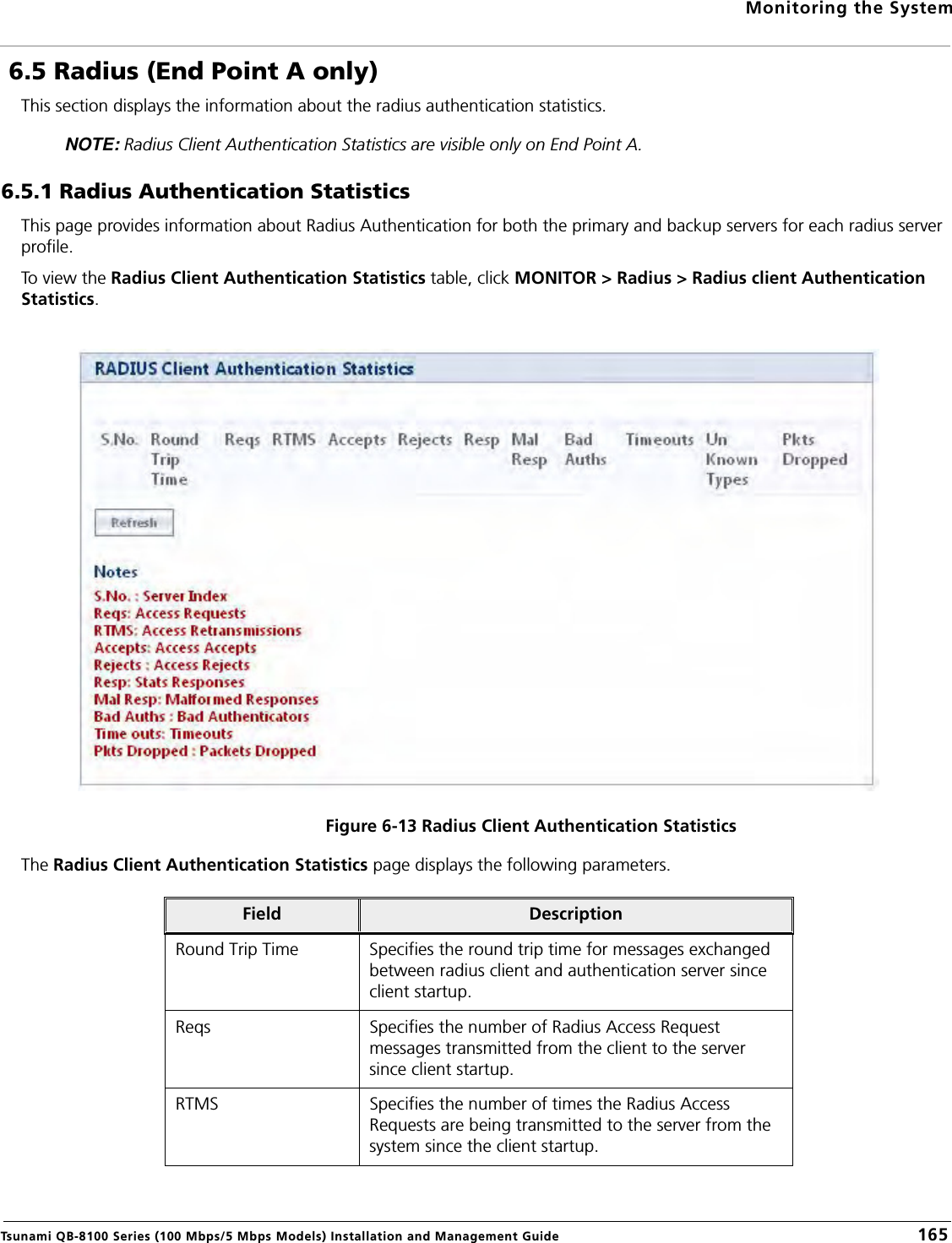
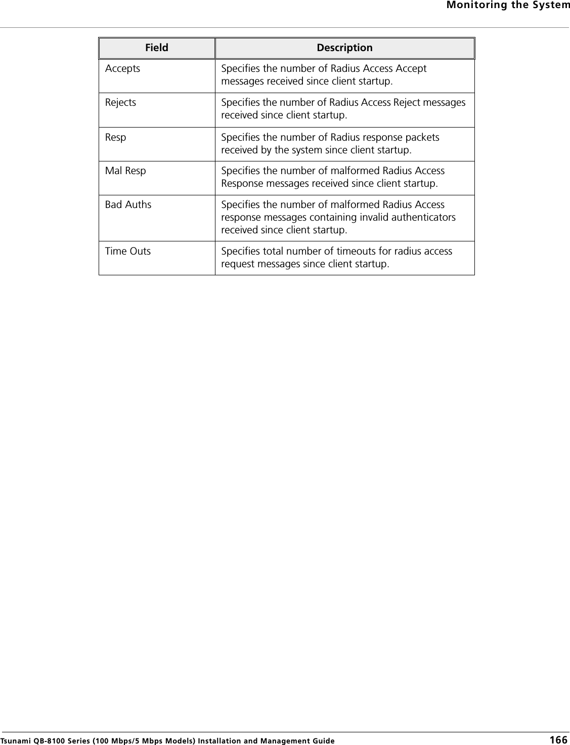
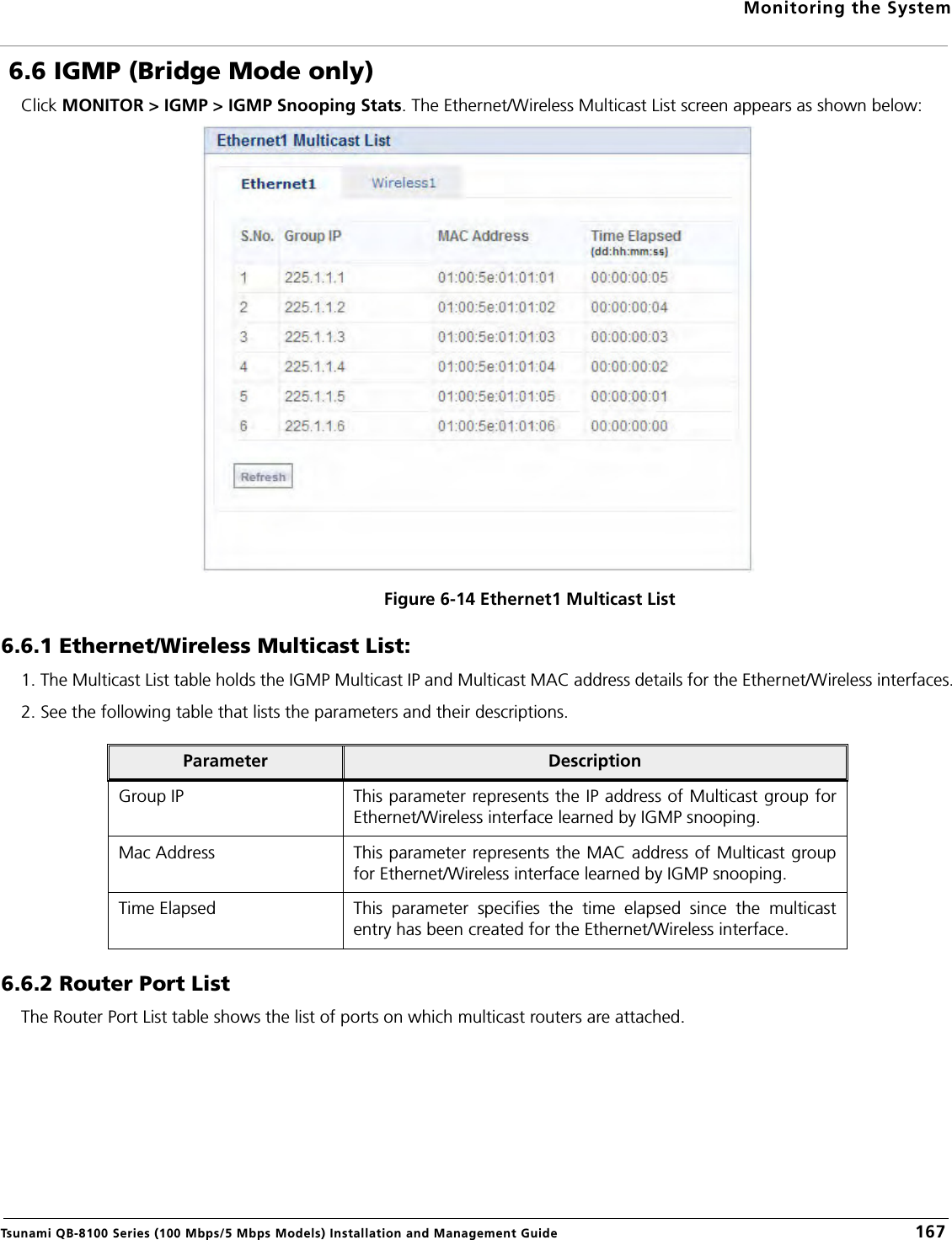
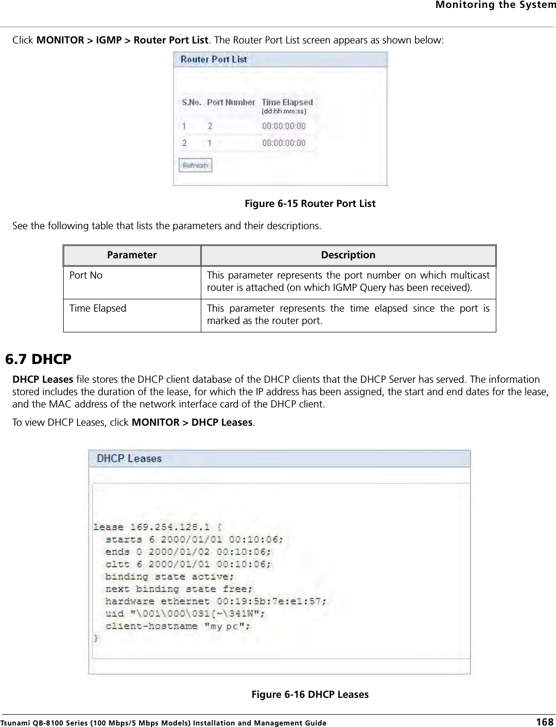
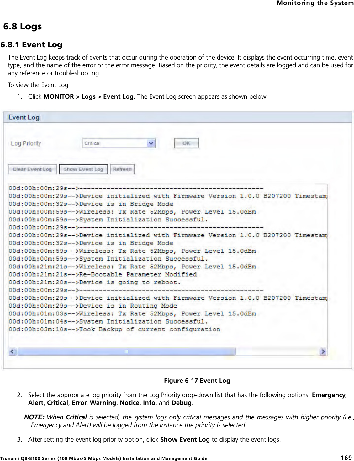
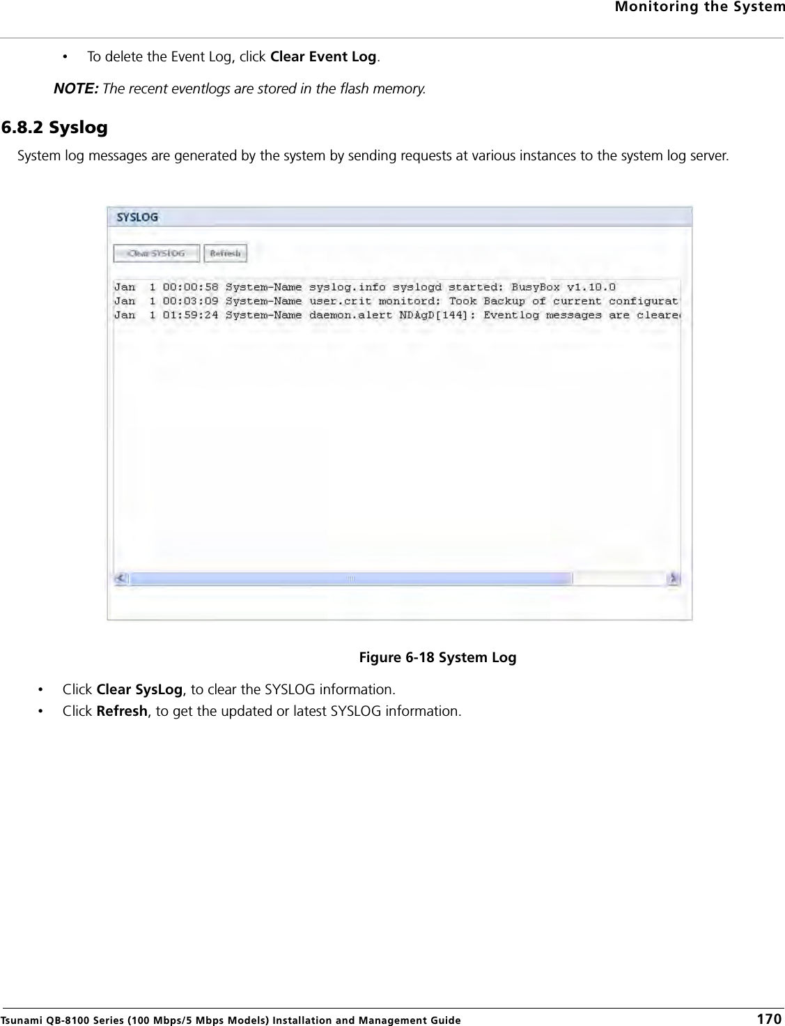
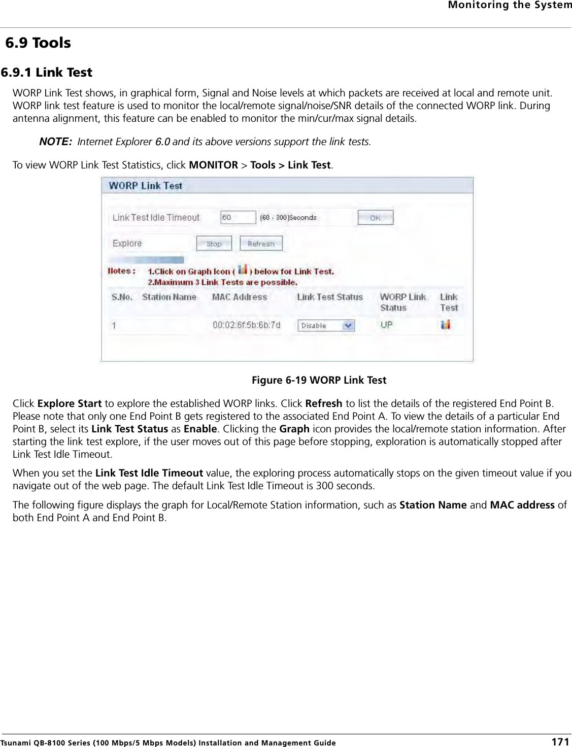
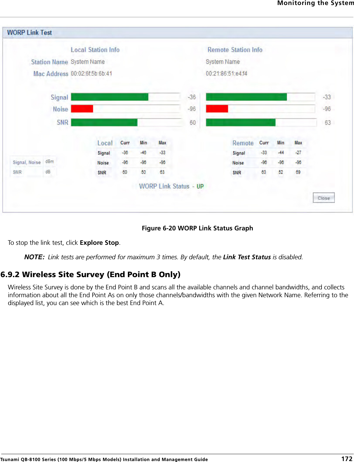
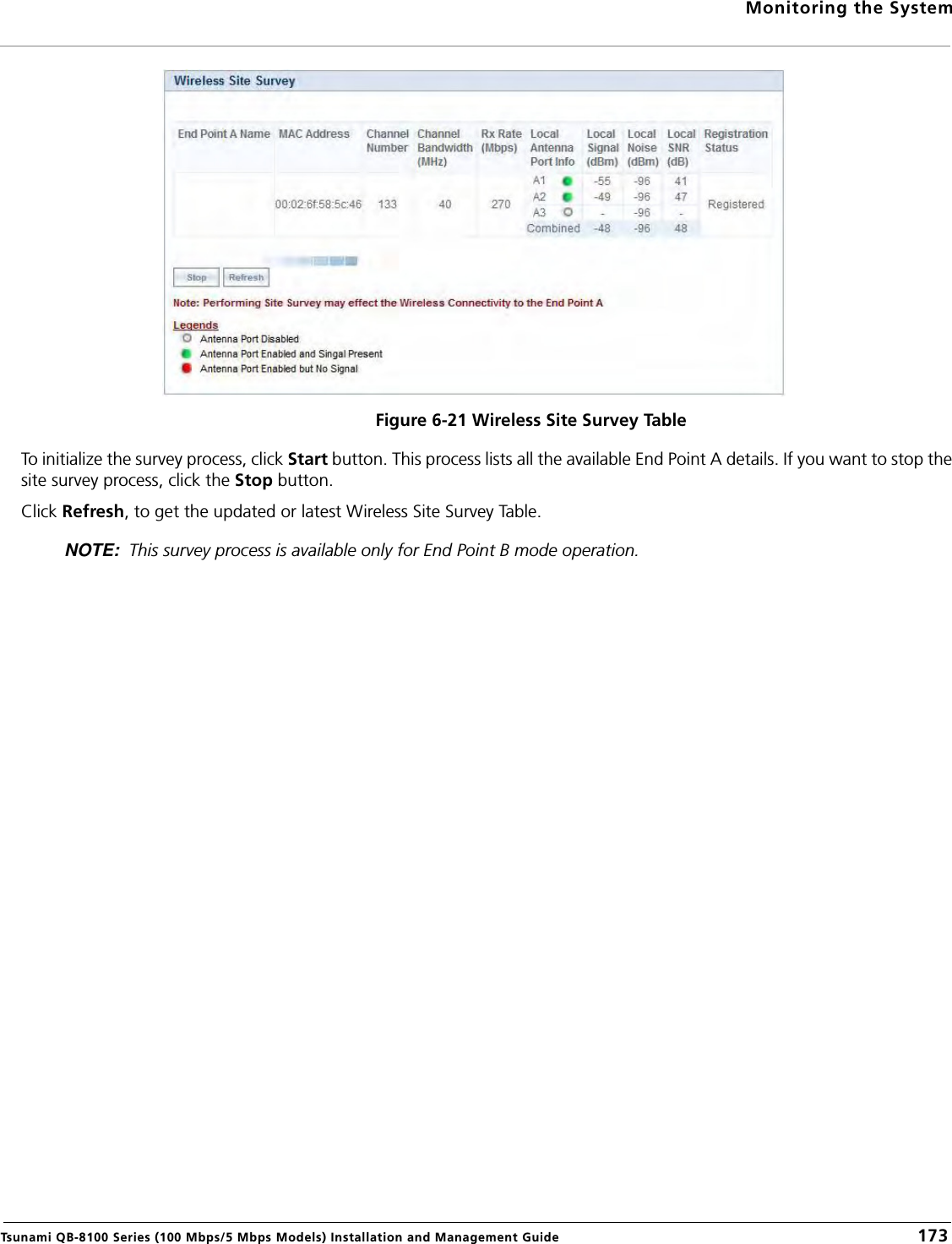
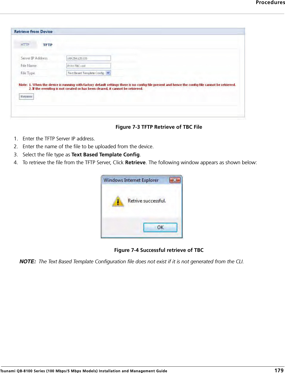
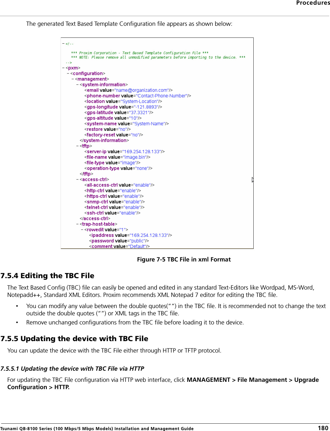
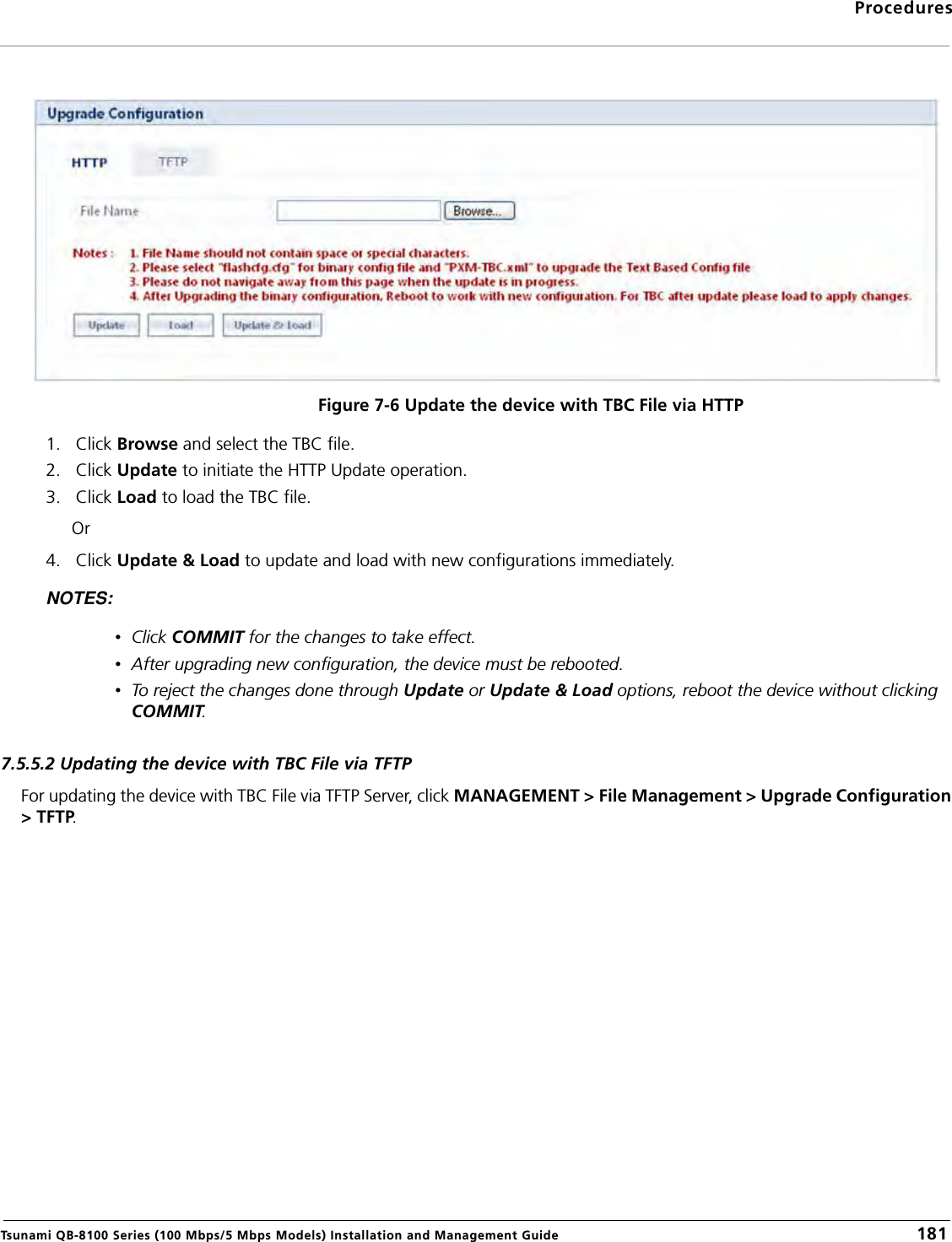
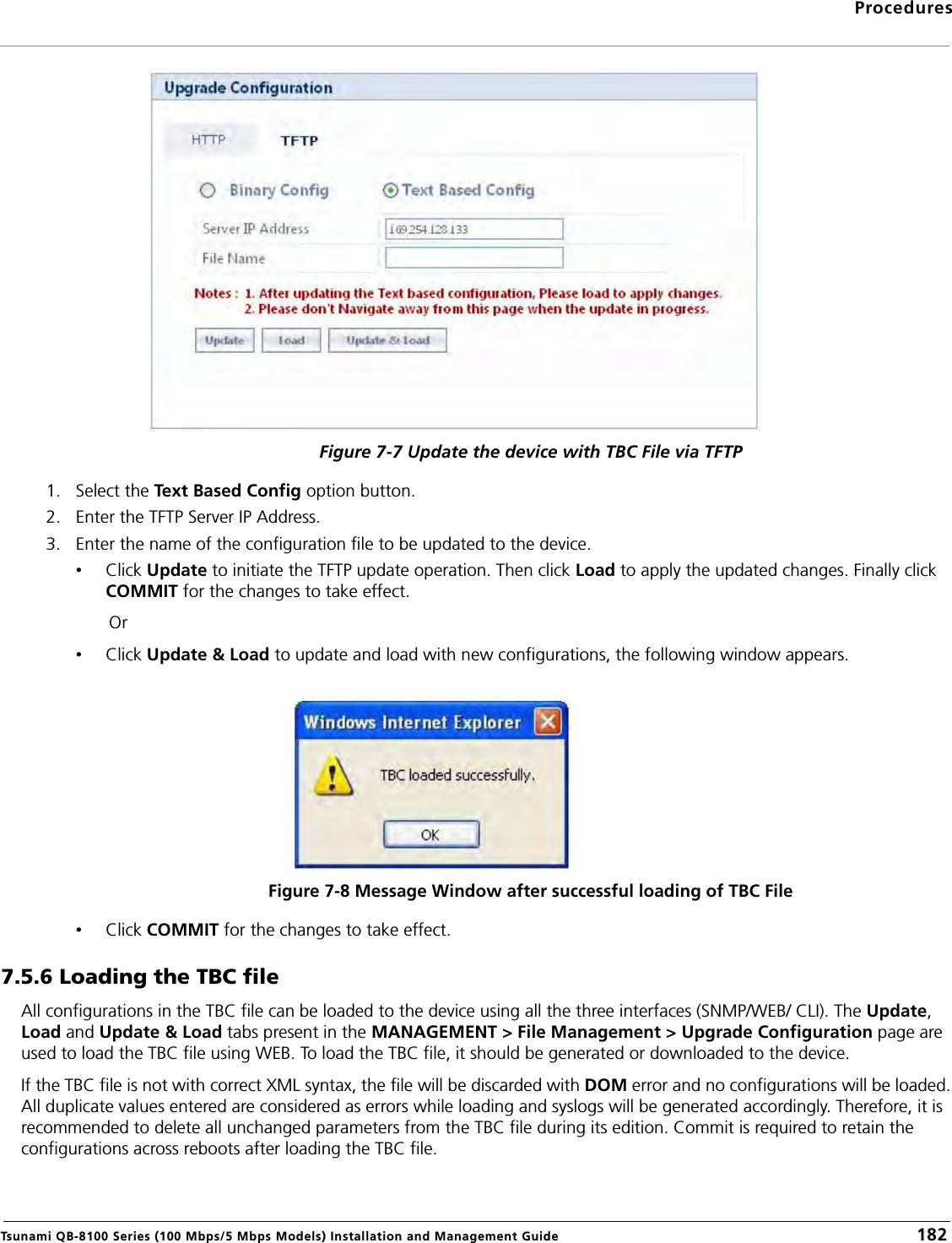
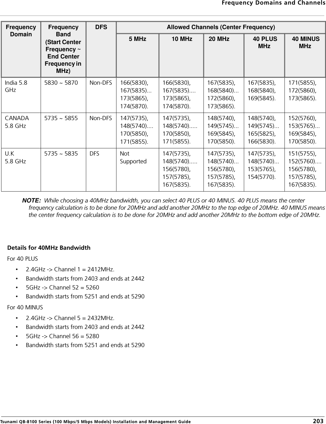
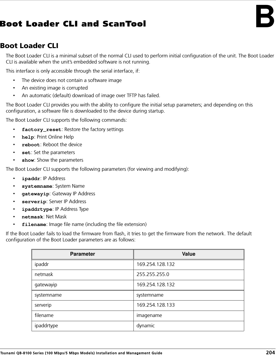
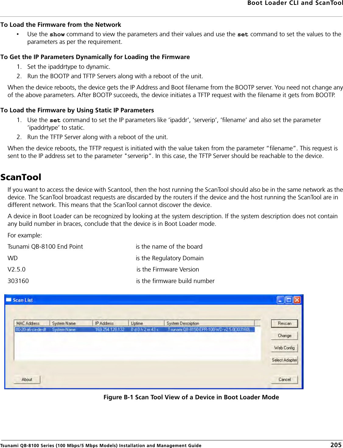
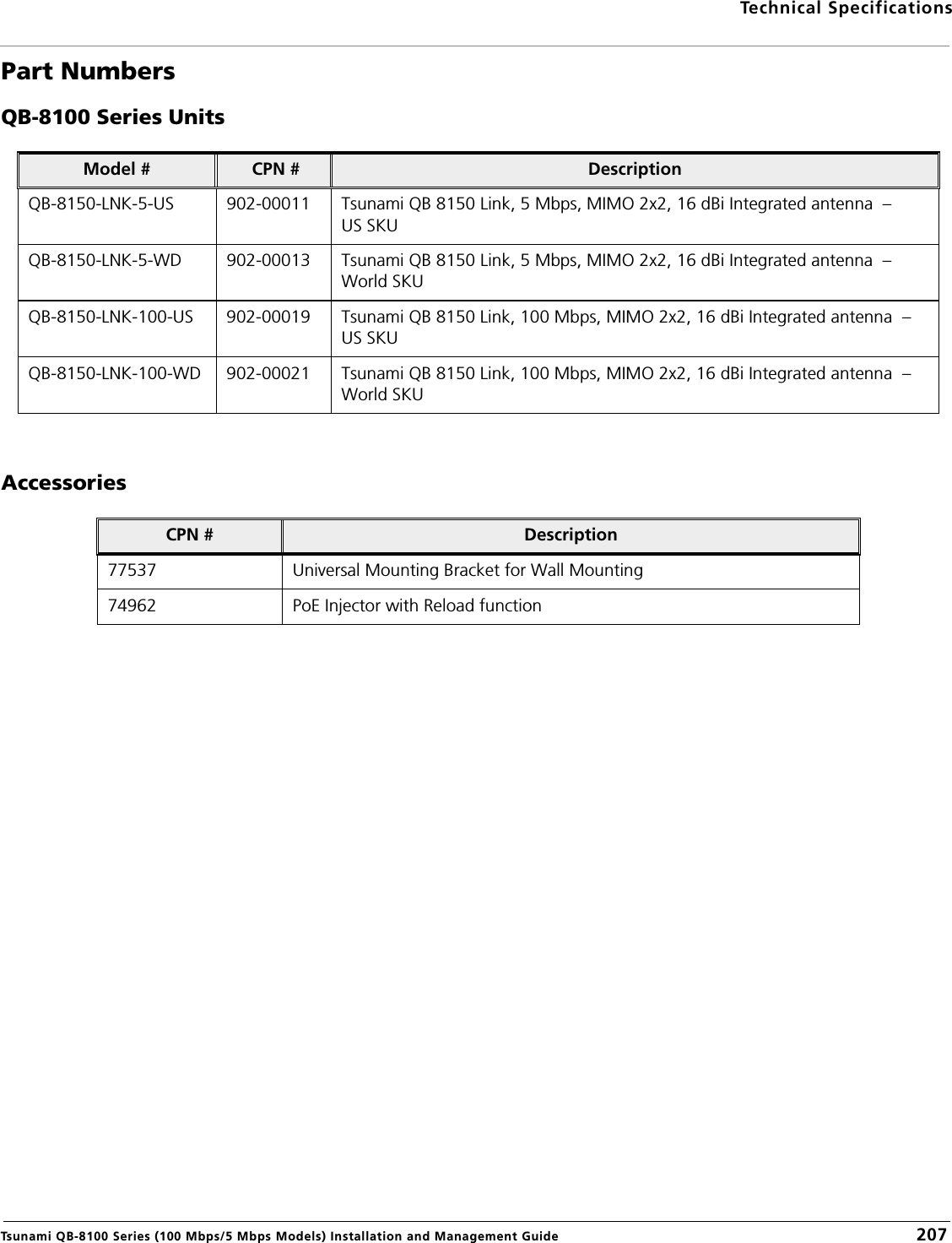
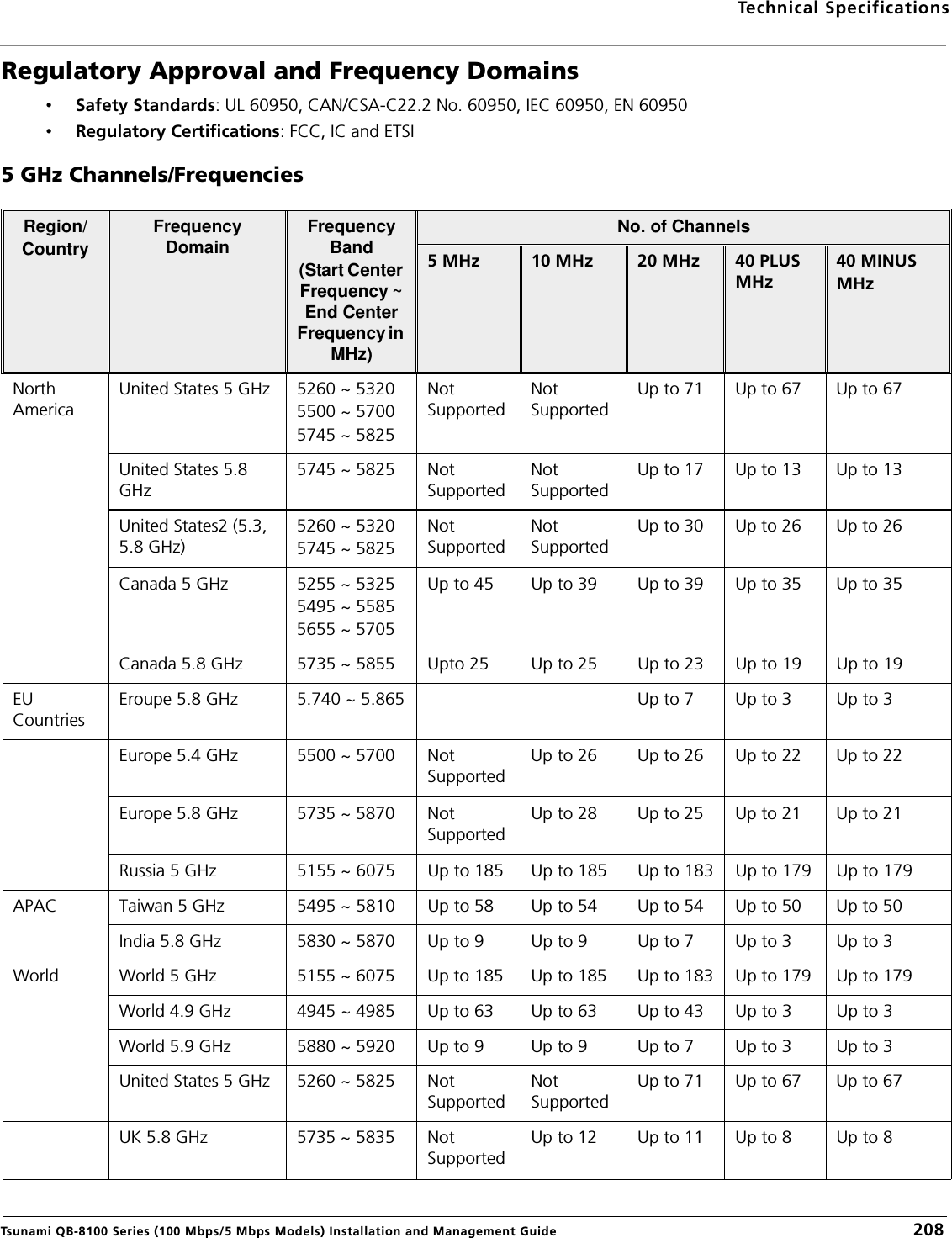
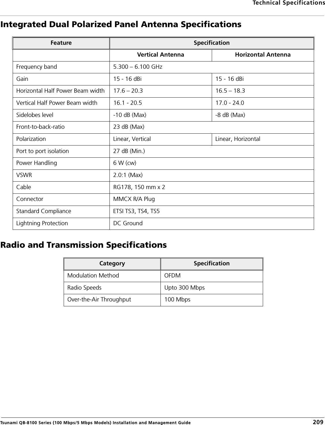
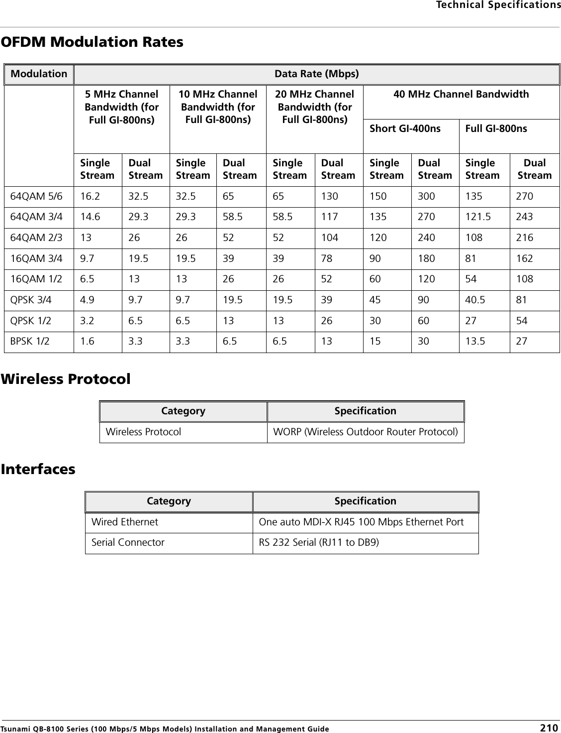
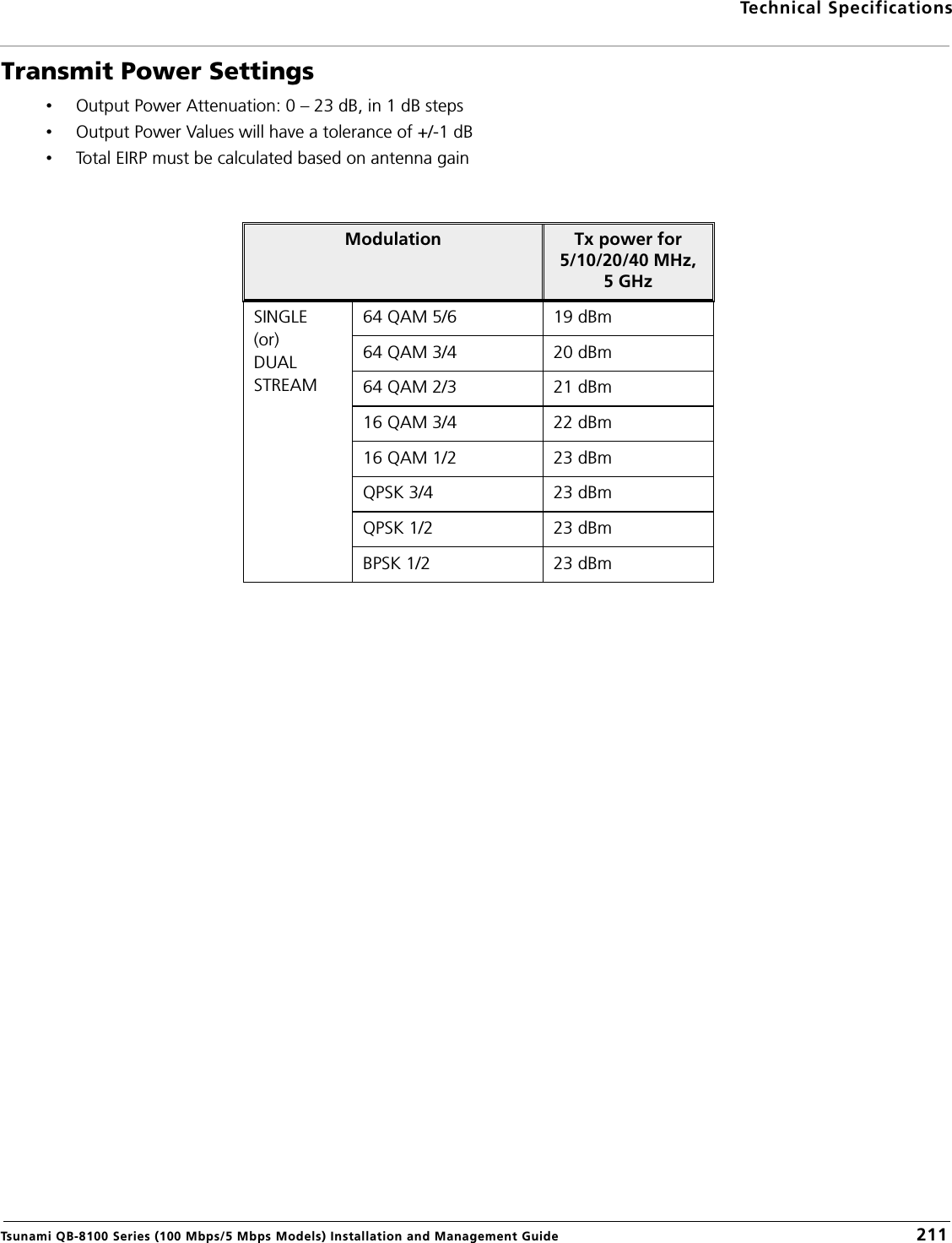
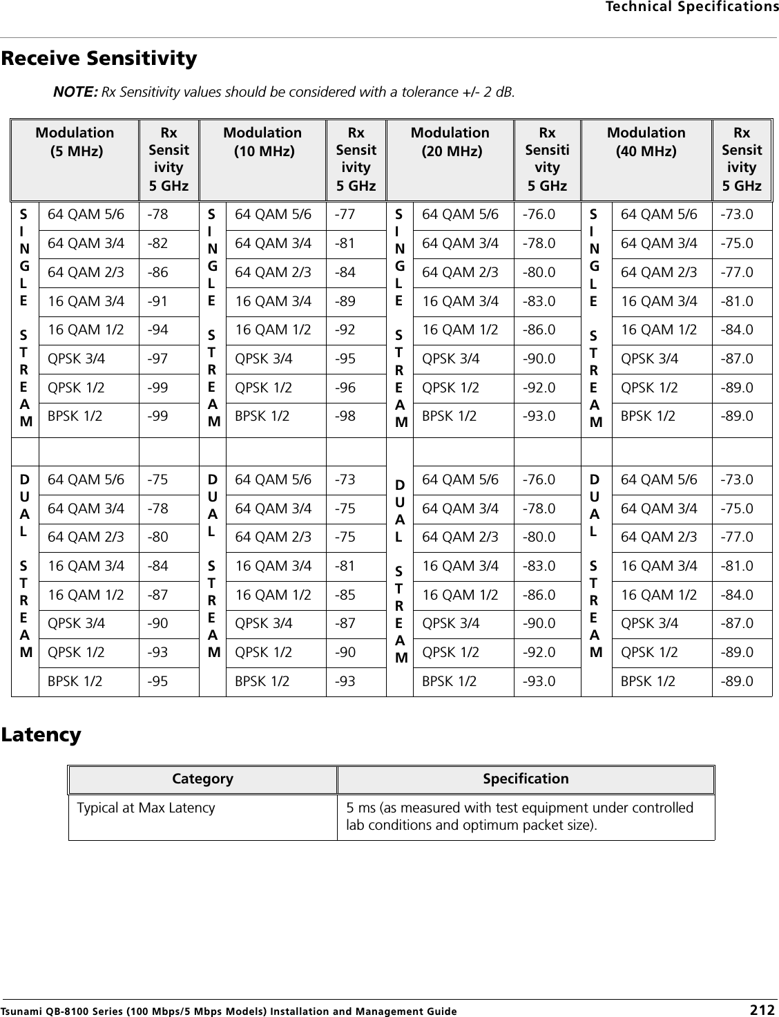
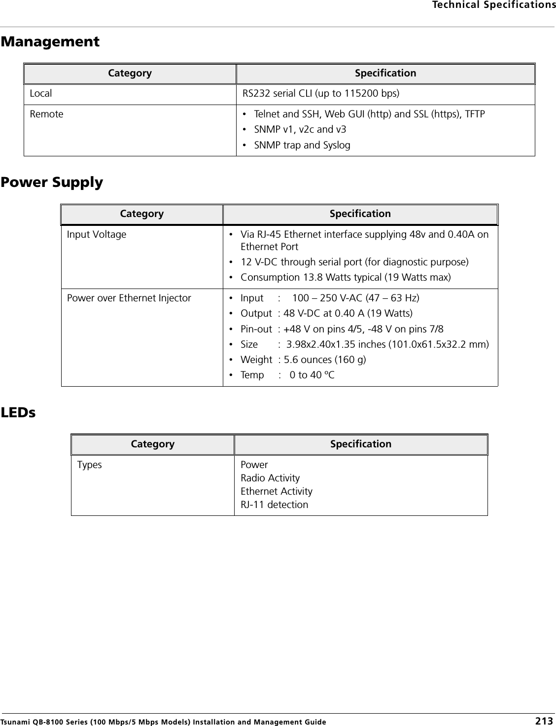
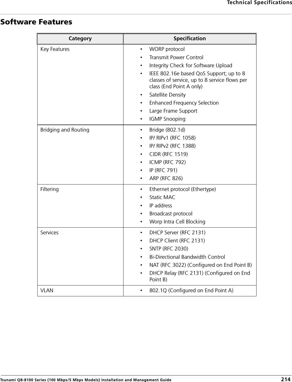
System user manual
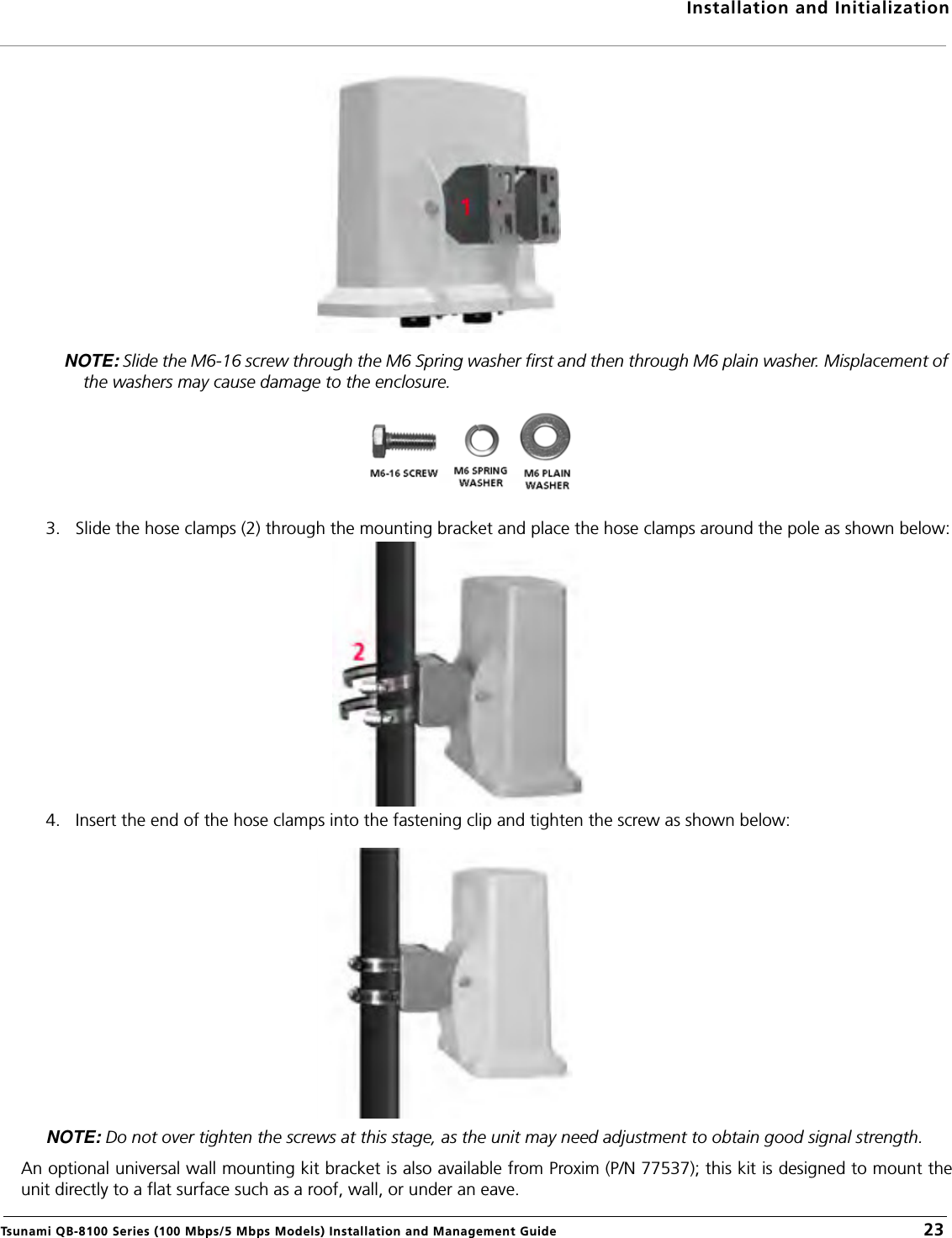
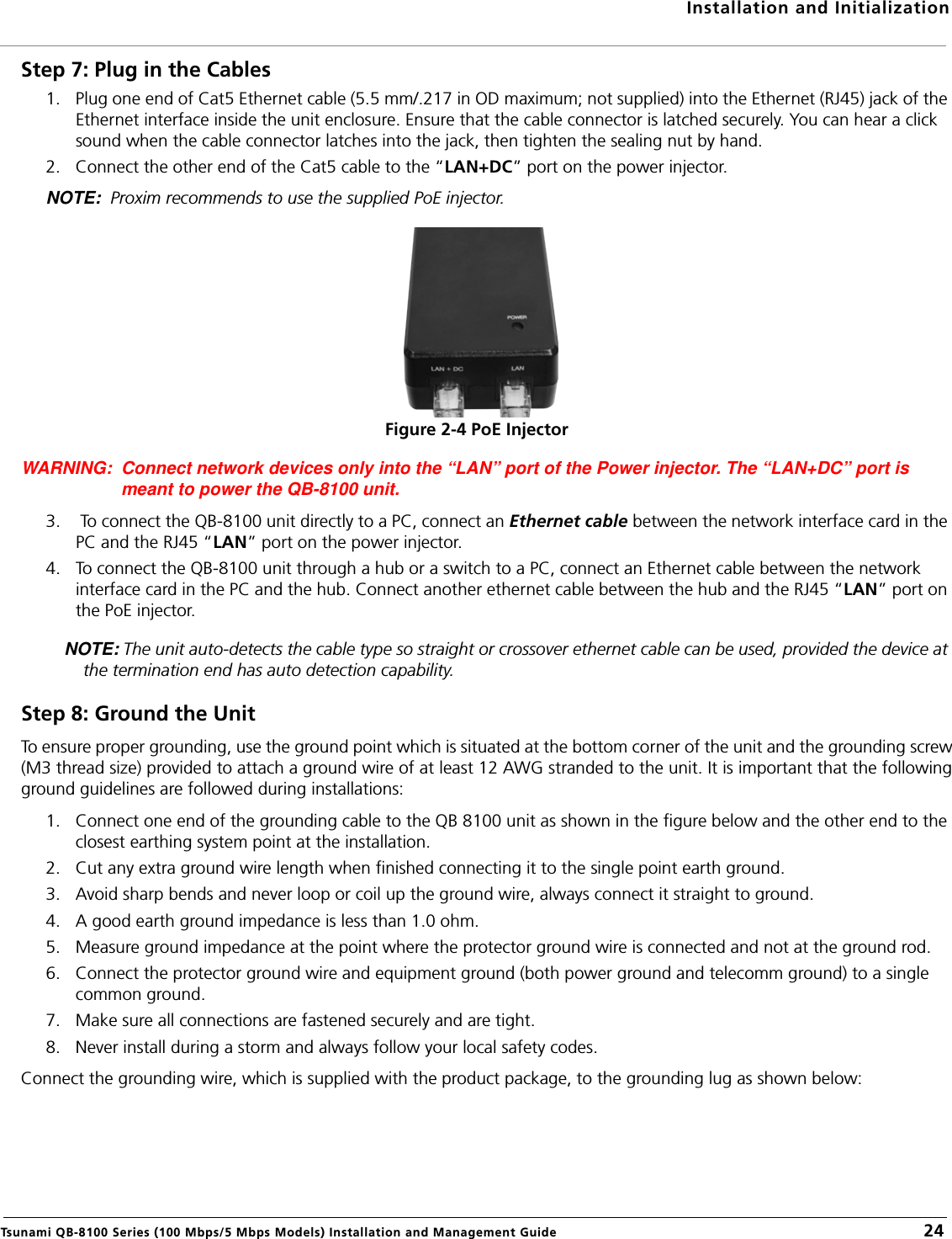
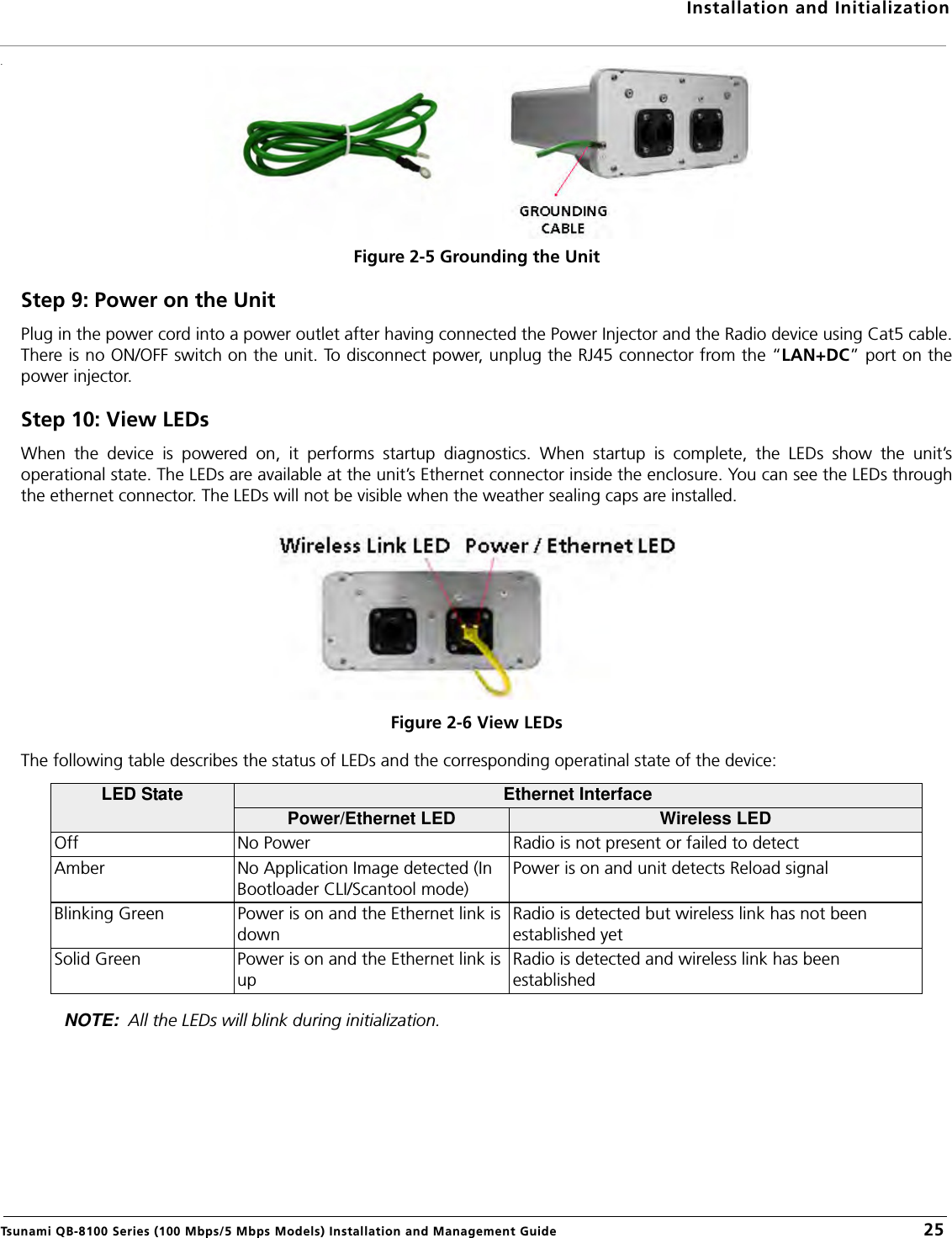
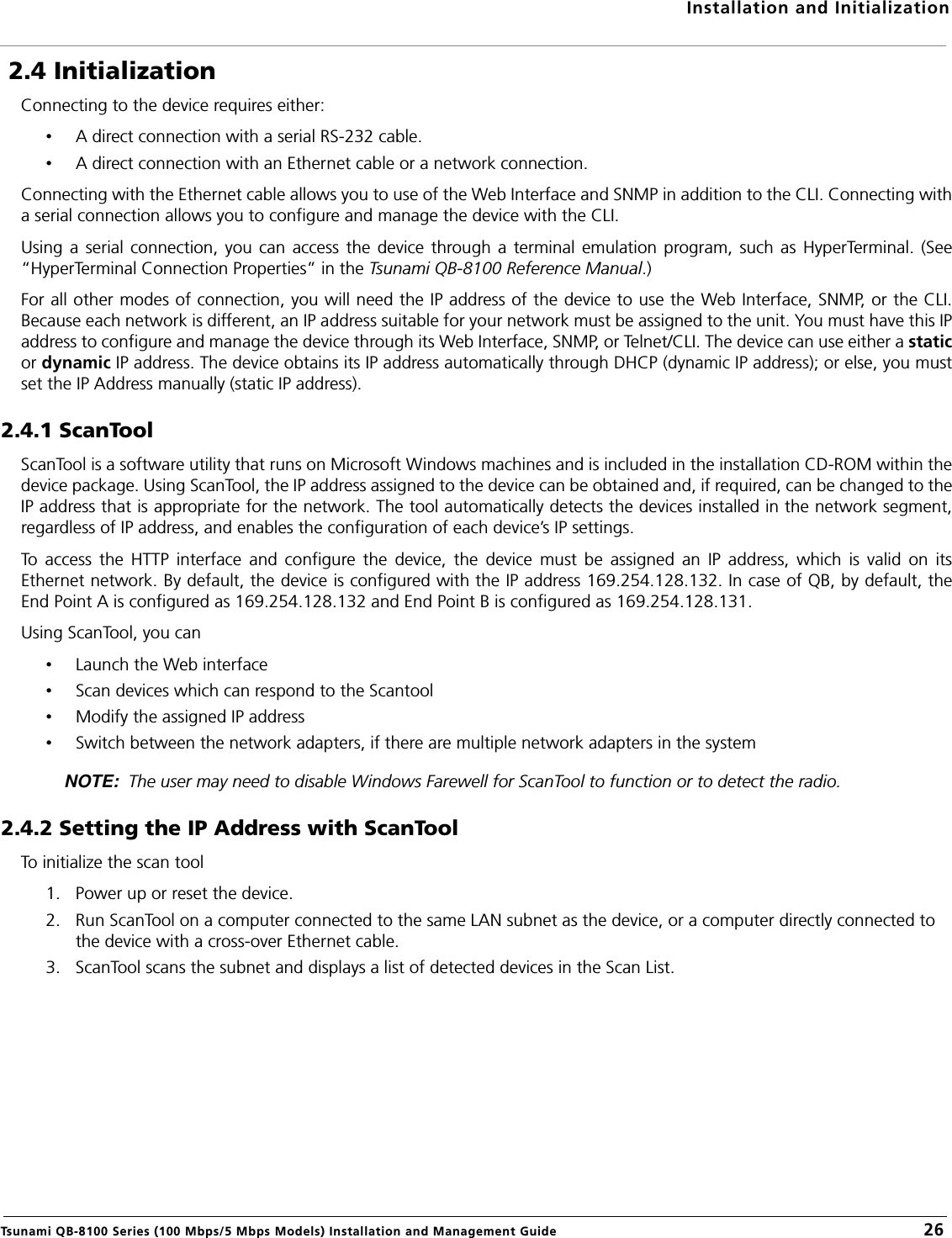
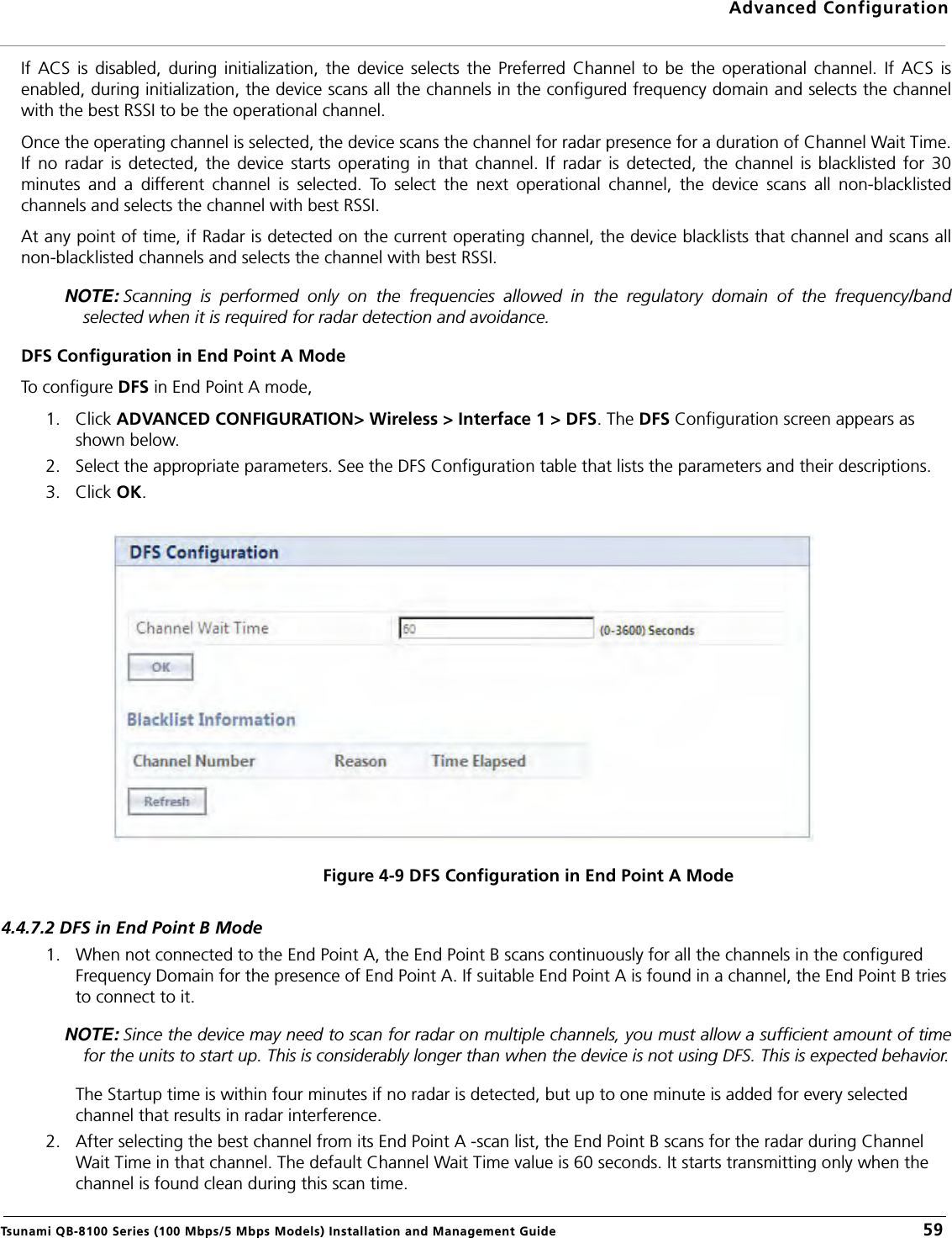
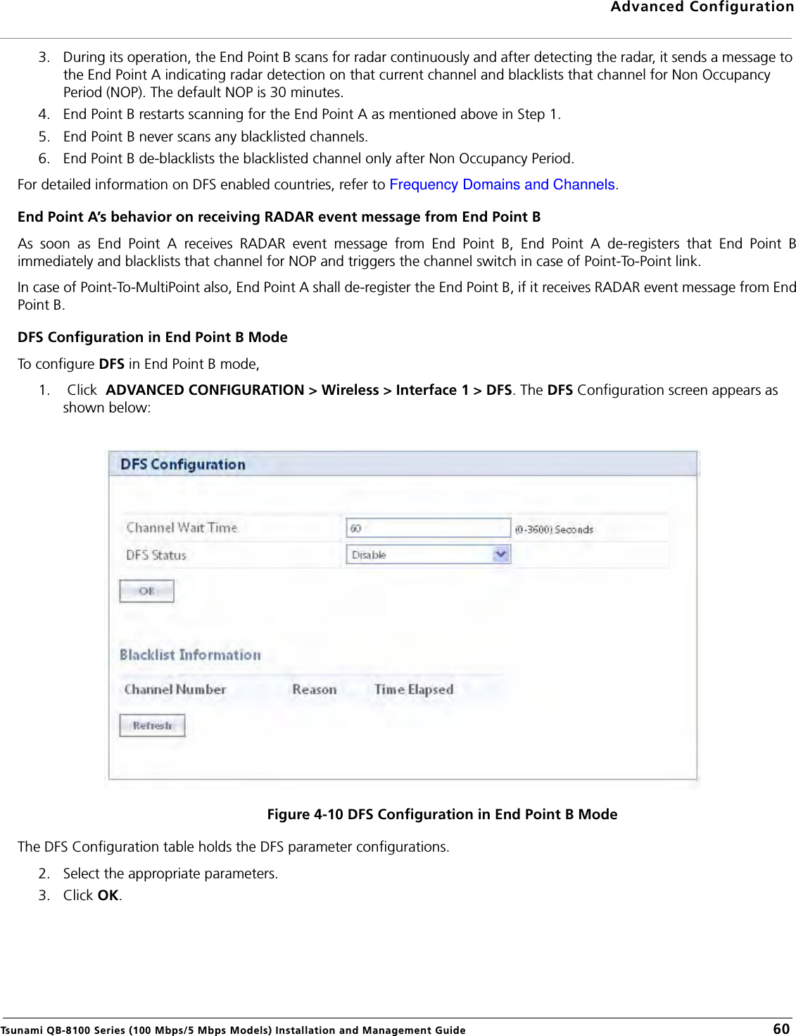
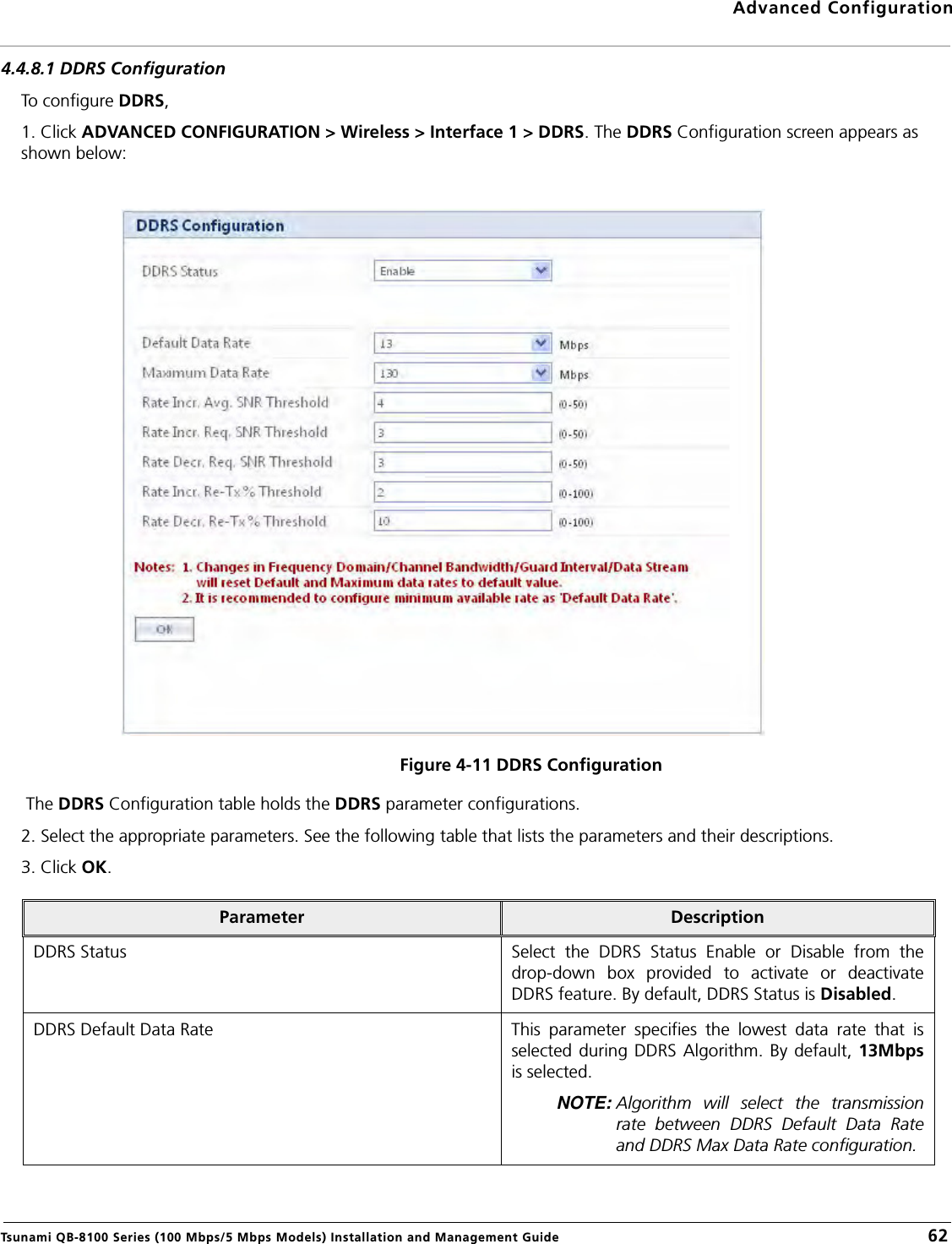
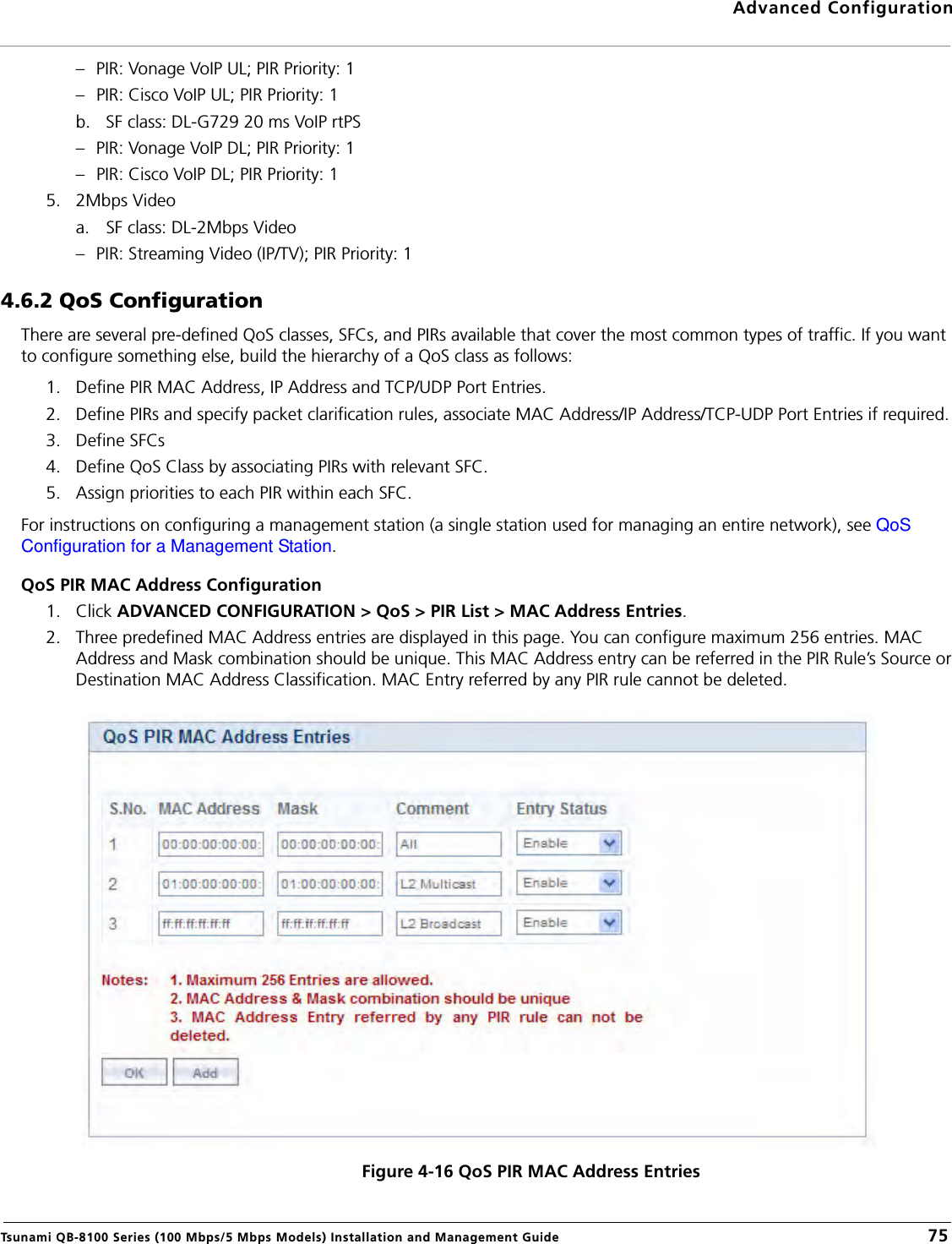
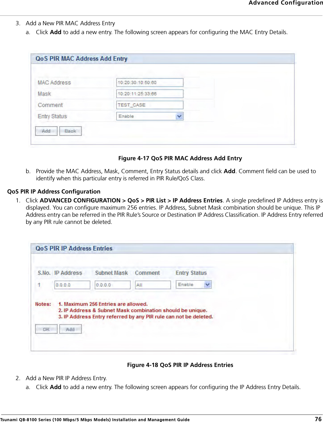
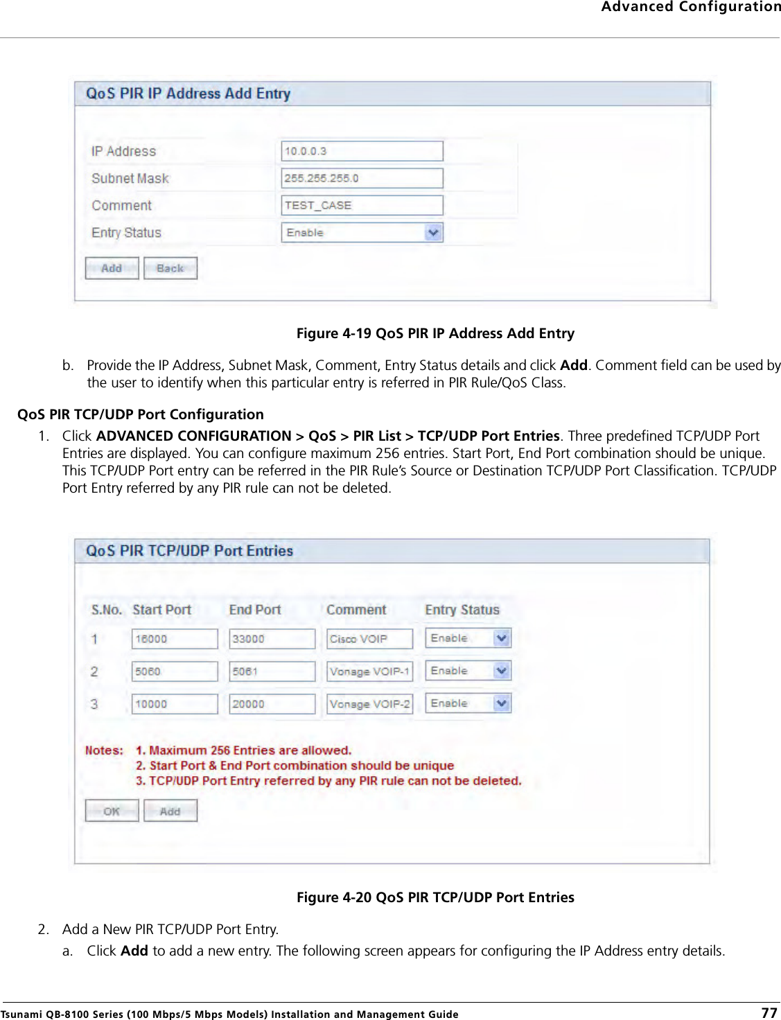
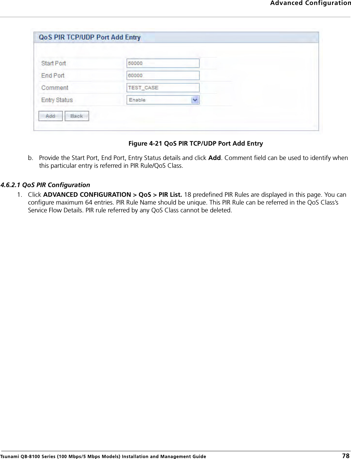
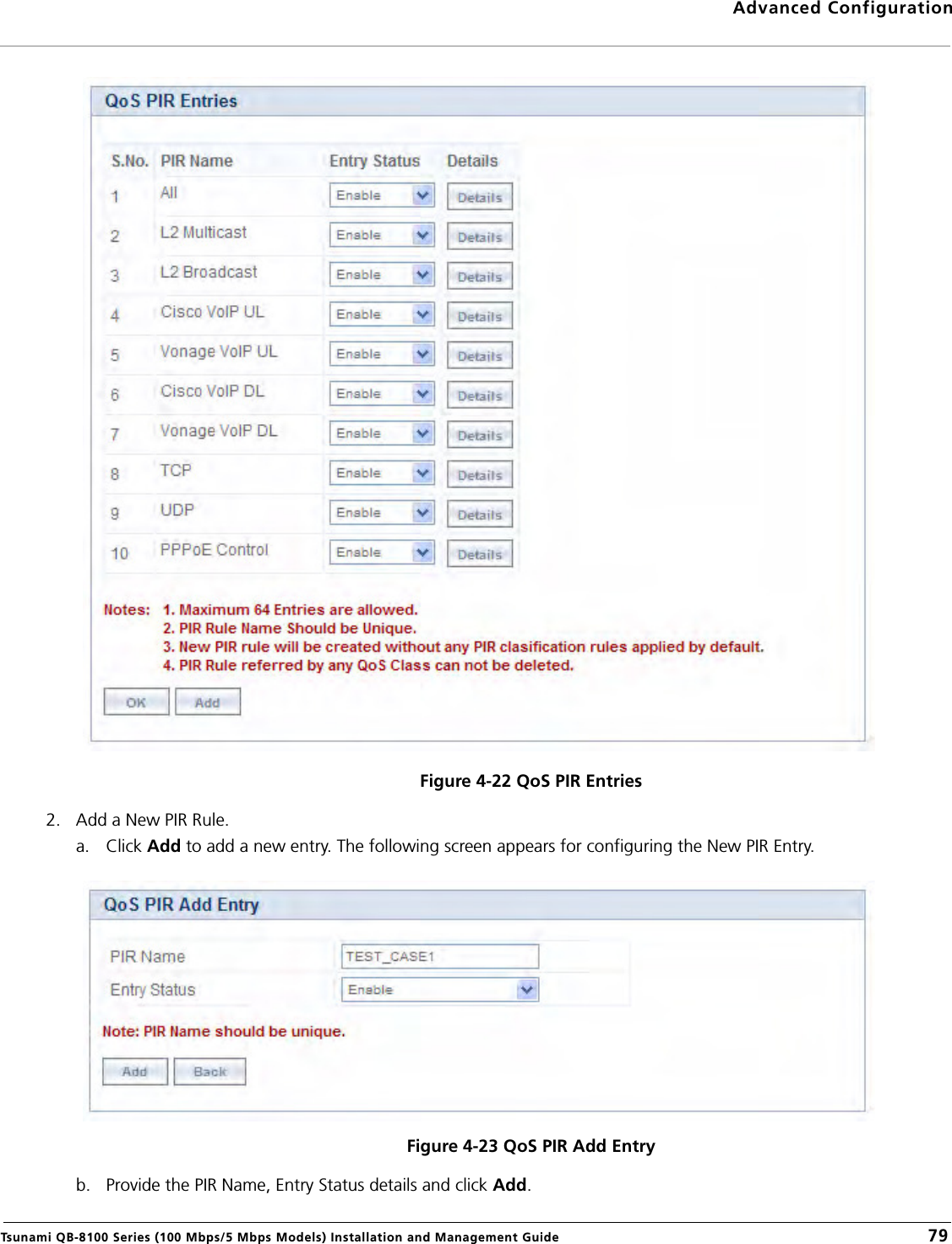
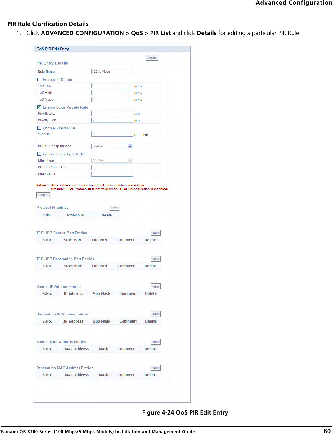
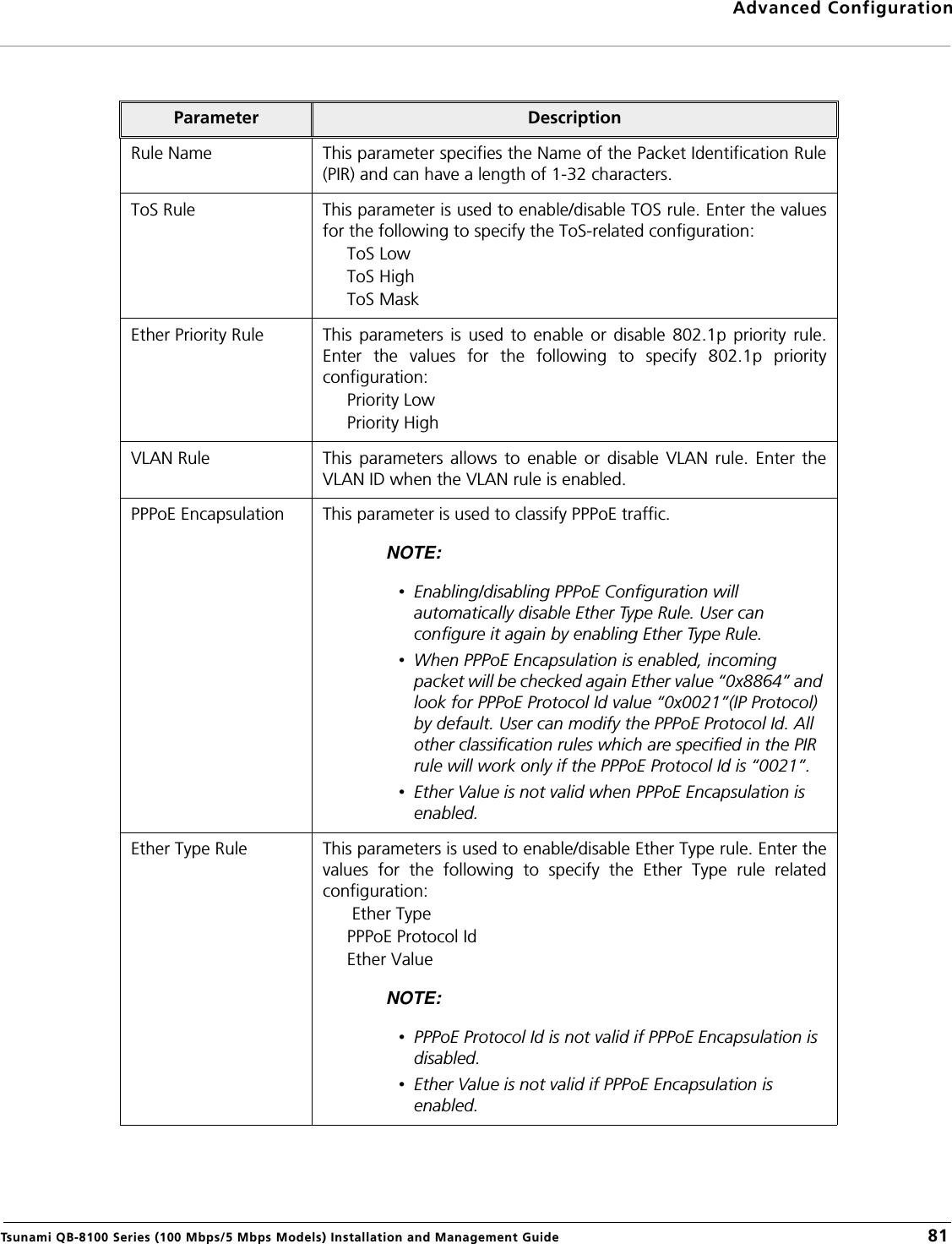
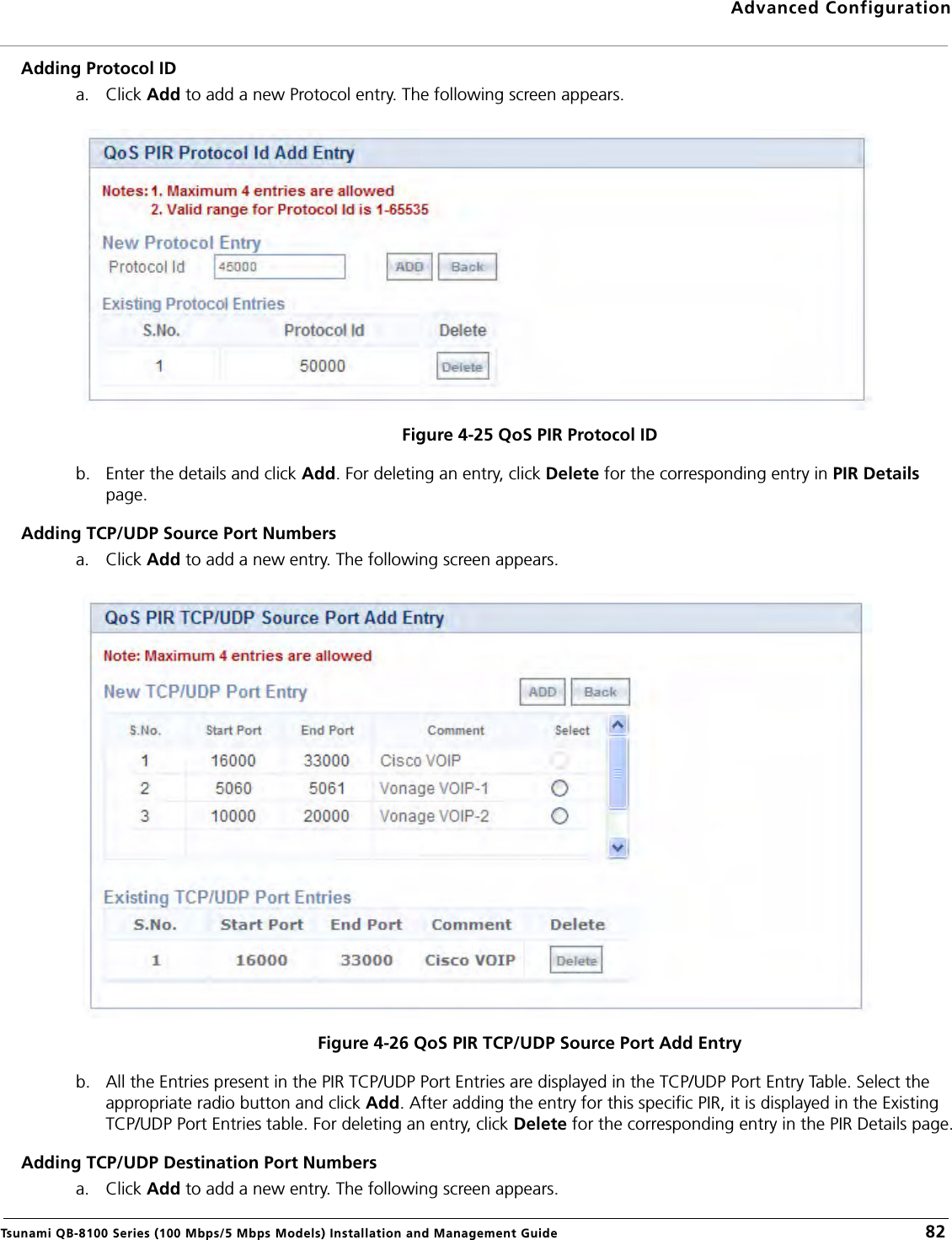
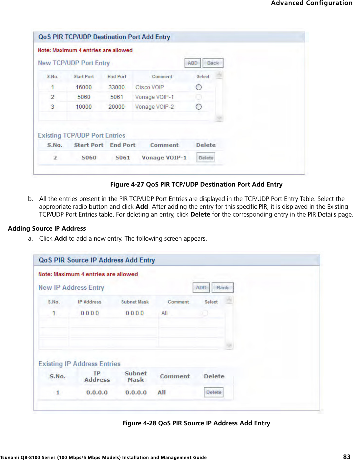
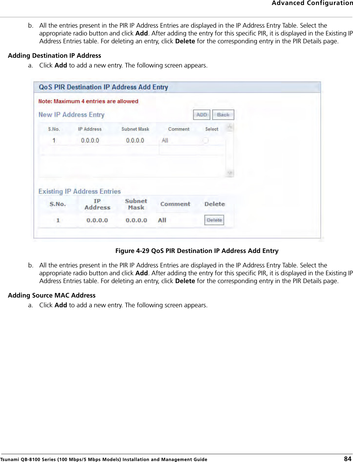
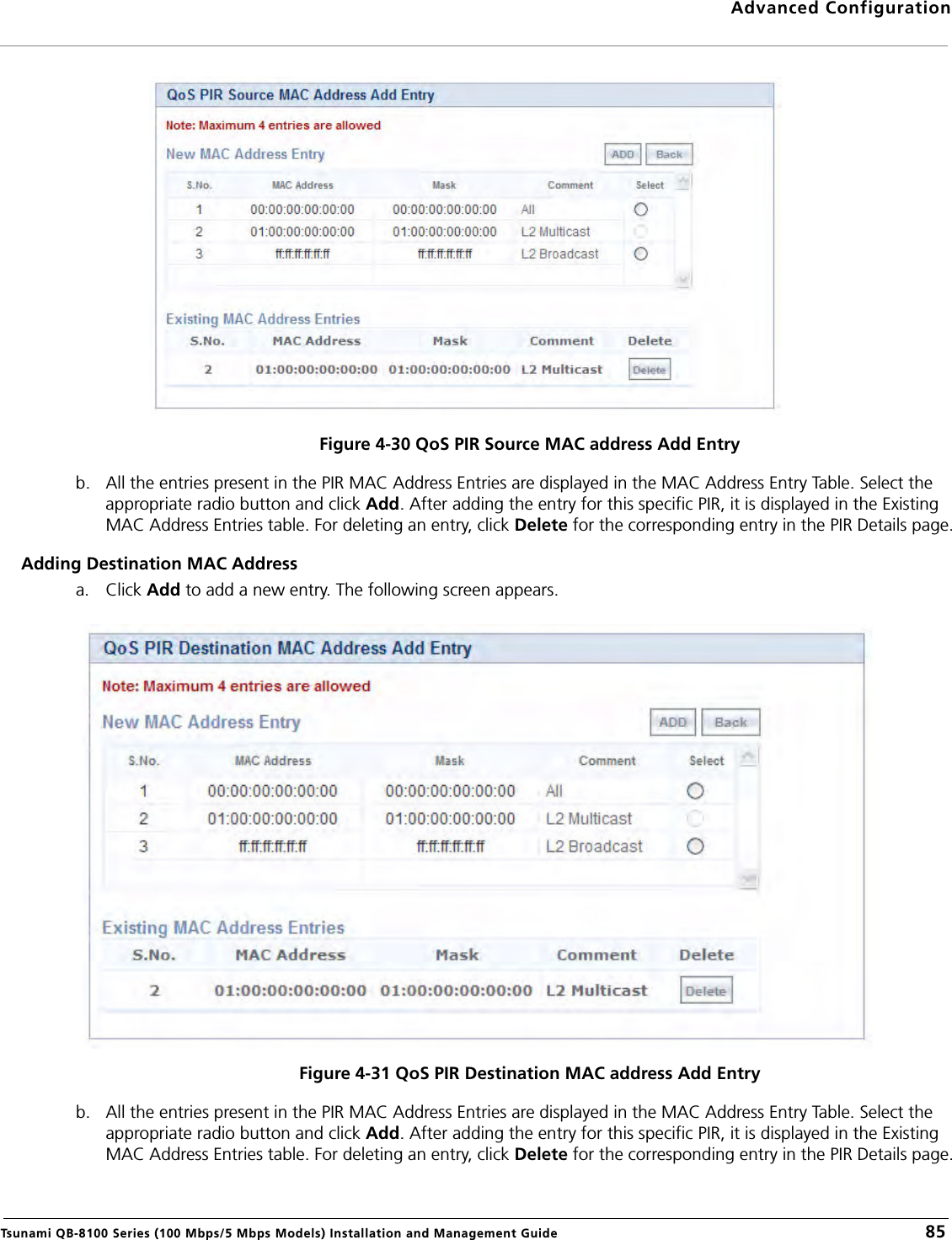
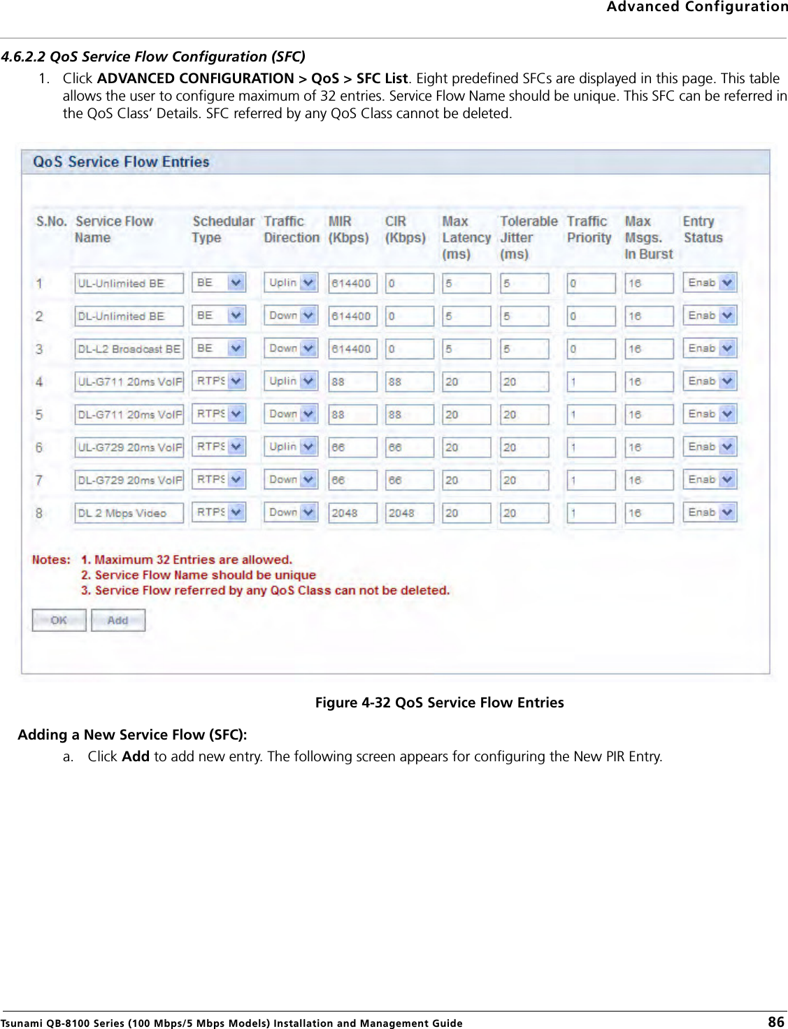
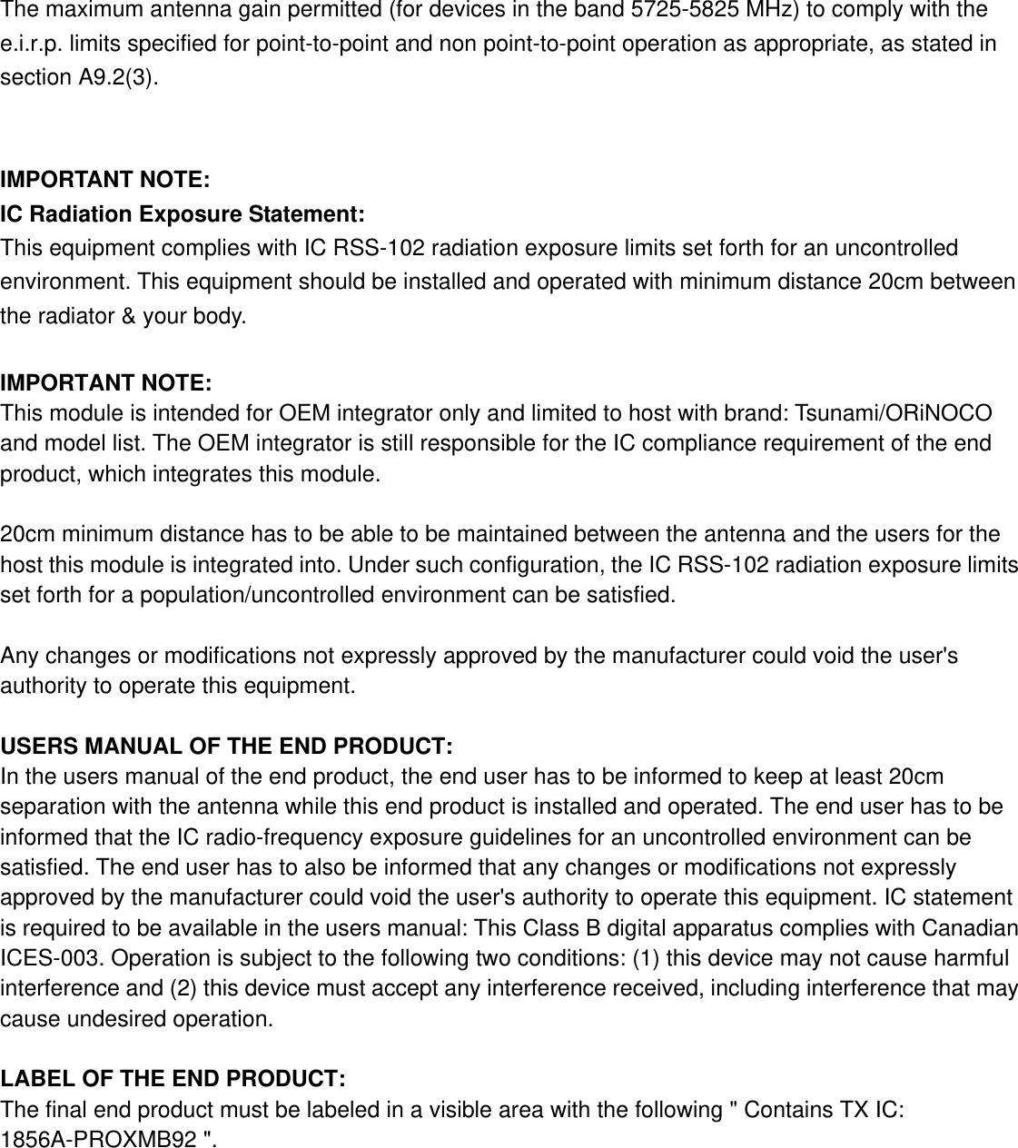
![IC Statement This Class B digital apparatus complies with Canadian ICES-003. Operation is subject to the following two conditions: (1) this device may not cause interference, and (2) this device must accept any interference, including interference that may cause undesired operation of the device. Cet appareil numérique de la classe B est conforme á la norme NMB-003 du Canada. For product available in the USA/Canada market, only channel 1~11 can be operated. Selection of other channels is not possible. This device and its antenna(s) must not be co-located or operation in conjunction with any other antenna or transmitter. To reduce potential radio interference to other users, the antenna type and its gain should be so chosen that the equivalent isotropically radiated power (e.i.r.p) is not more than that permitted for successful communication. This device has been designed to operate with the antennas listed below, and having a maximum gain of [30] dB. Antennas not included in this list or having a gain greater than [30] dB are strictly prohibited for use with this device. The required antenna impedance is 50 ohms. The device could automatically discontinue transmission in case of absence of information to transmit, or operational failure. Note that this is not intended to prohibit transmission of control or signaling information or the use of repetitive codes where required by the technology. The device for the band 5150-5250 MHz is only for indoor usage to reduce potential for harmful interference to co-channel mobile satellite systems.](https://usermanual.wiki/Proxim-Wireless/PROXMB92.System-user-manual/User-Guide-1535110-Page-225.png)