Proxim Wireless MP11R-ABG MP.11x outdoor wireless Etherenet system User Manual MP 11 R FCC
Proxim Wireless Corporation MP.11x outdoor wireless Etherenet system MP 11 R FCC
UserManual.wiki
>
Proxim Wireless
>
MP11R-ABG User Manual
>
manual 1
Contents
1.
Users Manual Part I
2.
Users Manual Part II
3.
Professional Installation Guide
4.
Regulatory Flyer
5.
manual 1
6.
manual 2
manual 1
Navigation menu
Upload a User Manual
Namespaces
Wiki Guide
HTML
PDF
Info
Views
User Manual
Discussion / Help
Navigation
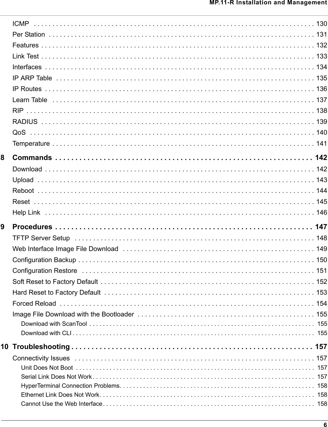

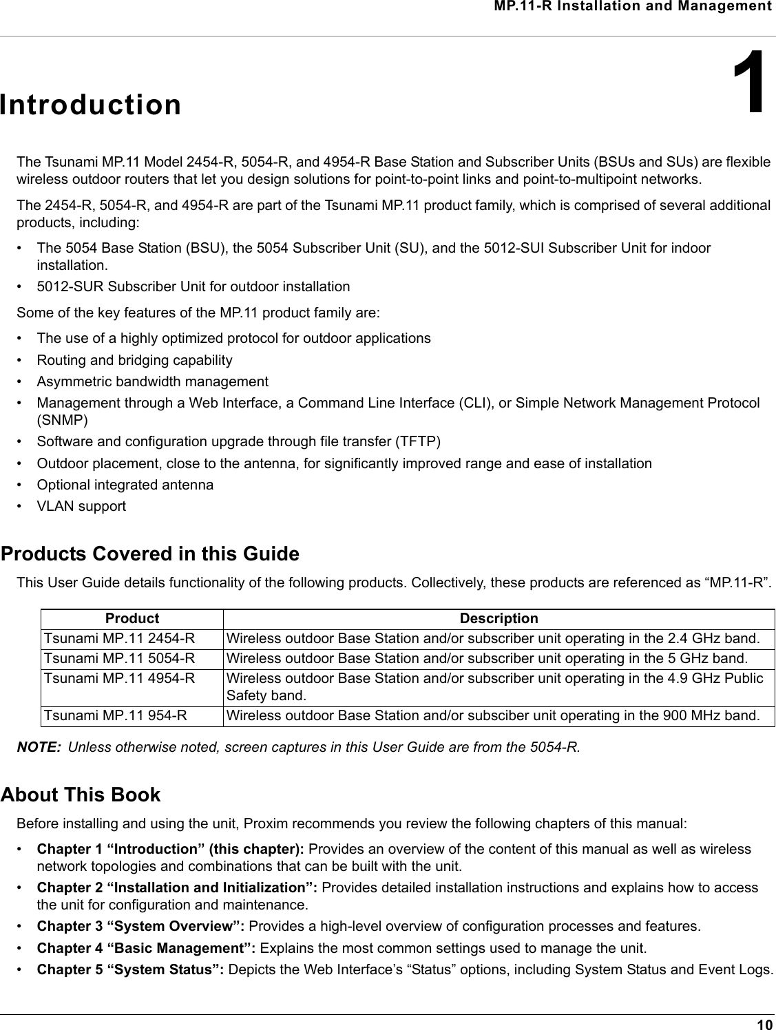
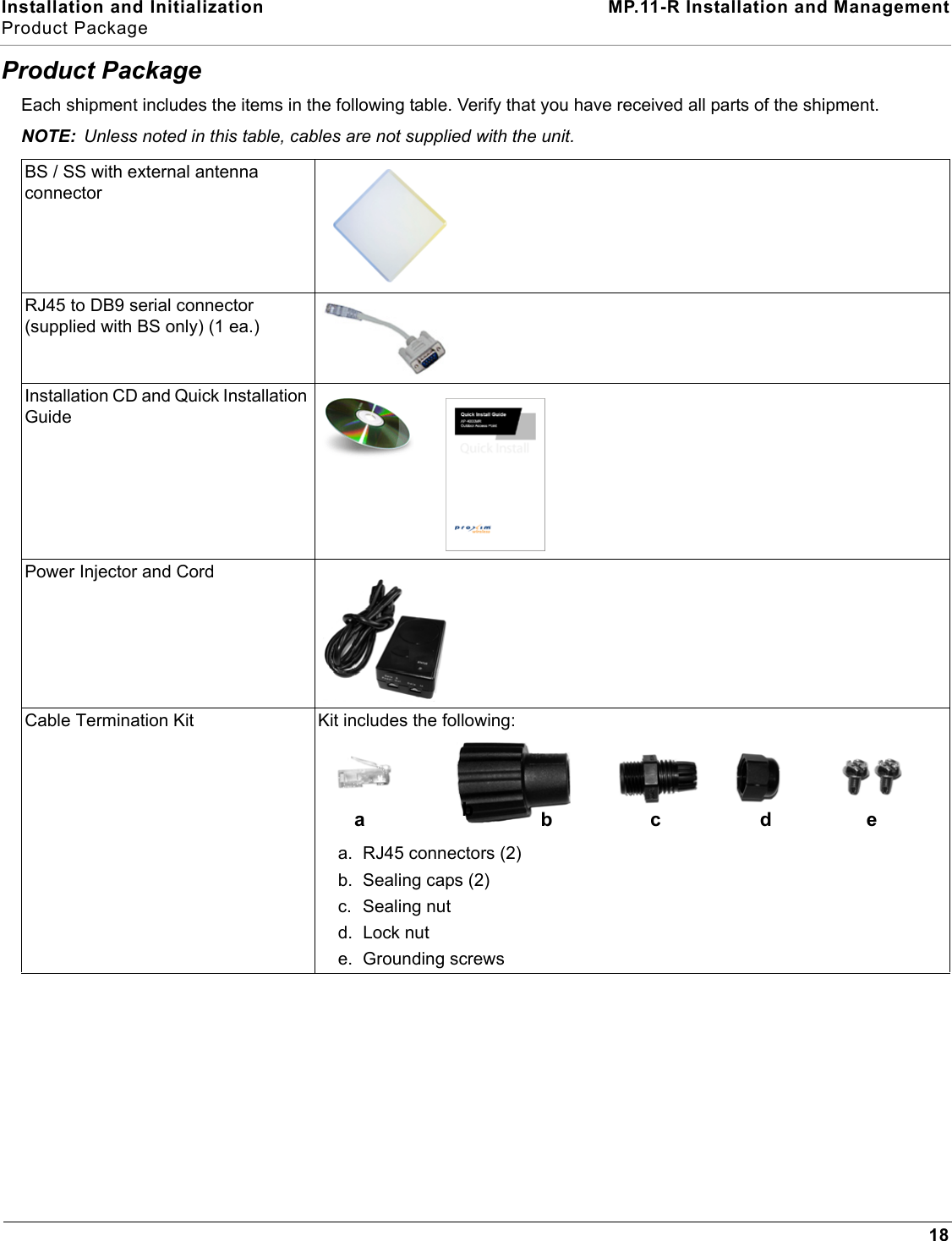
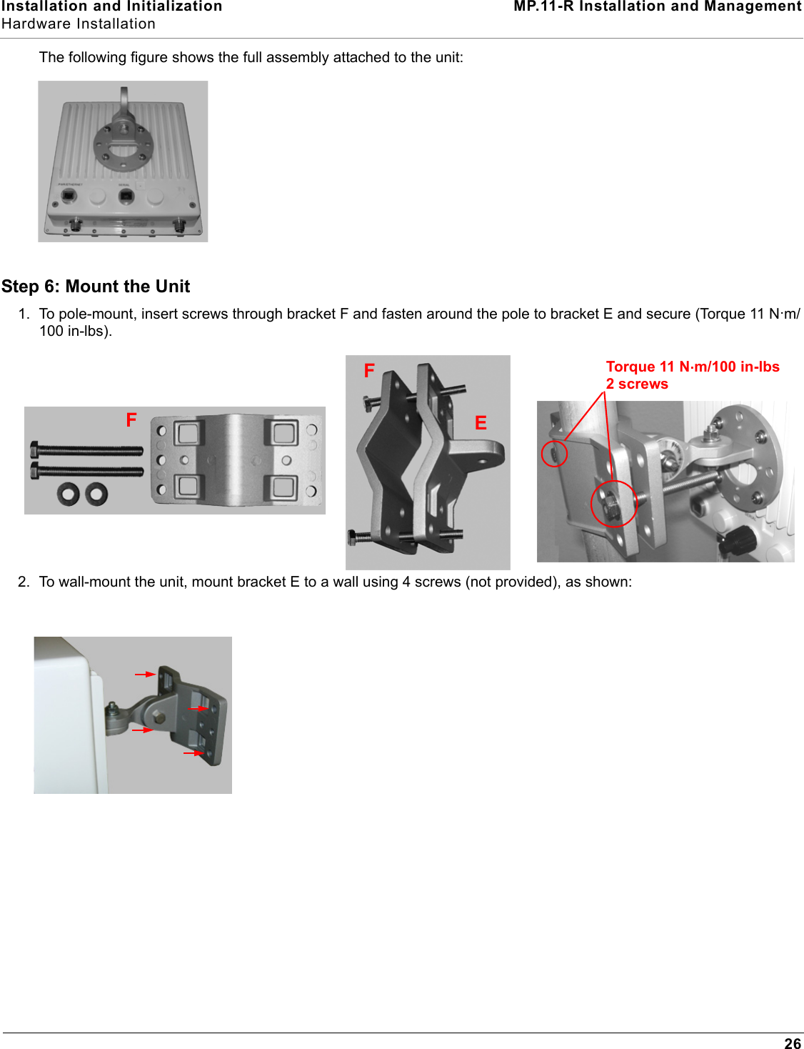
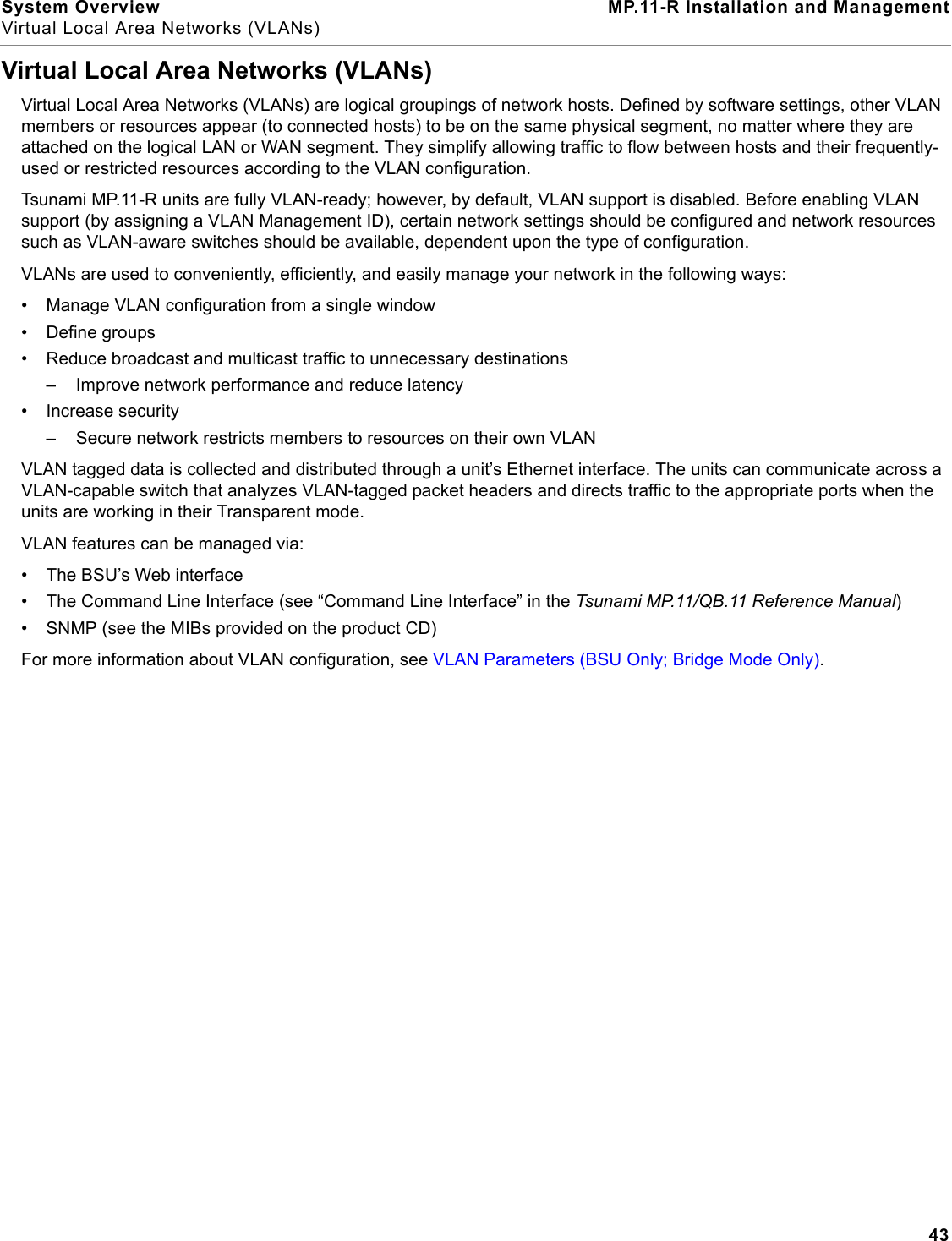
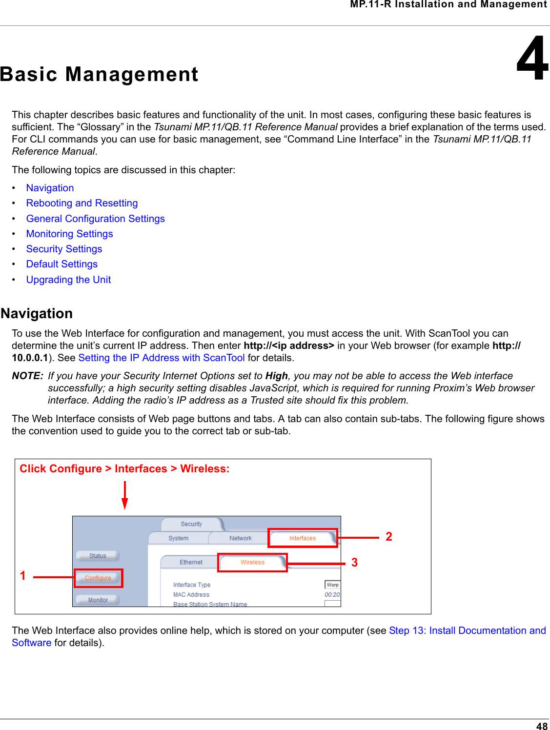
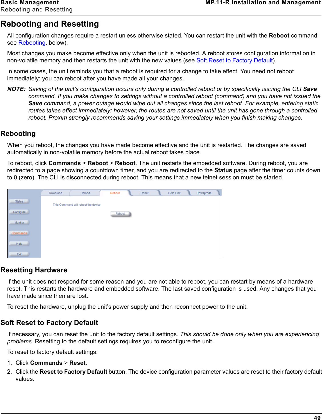
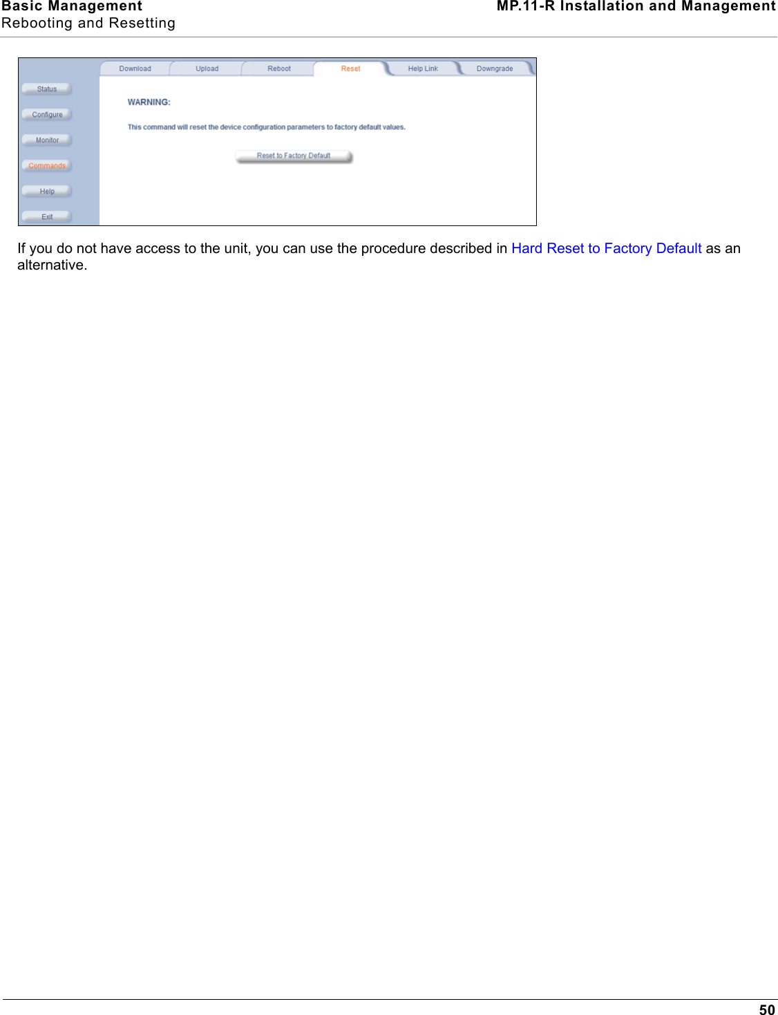
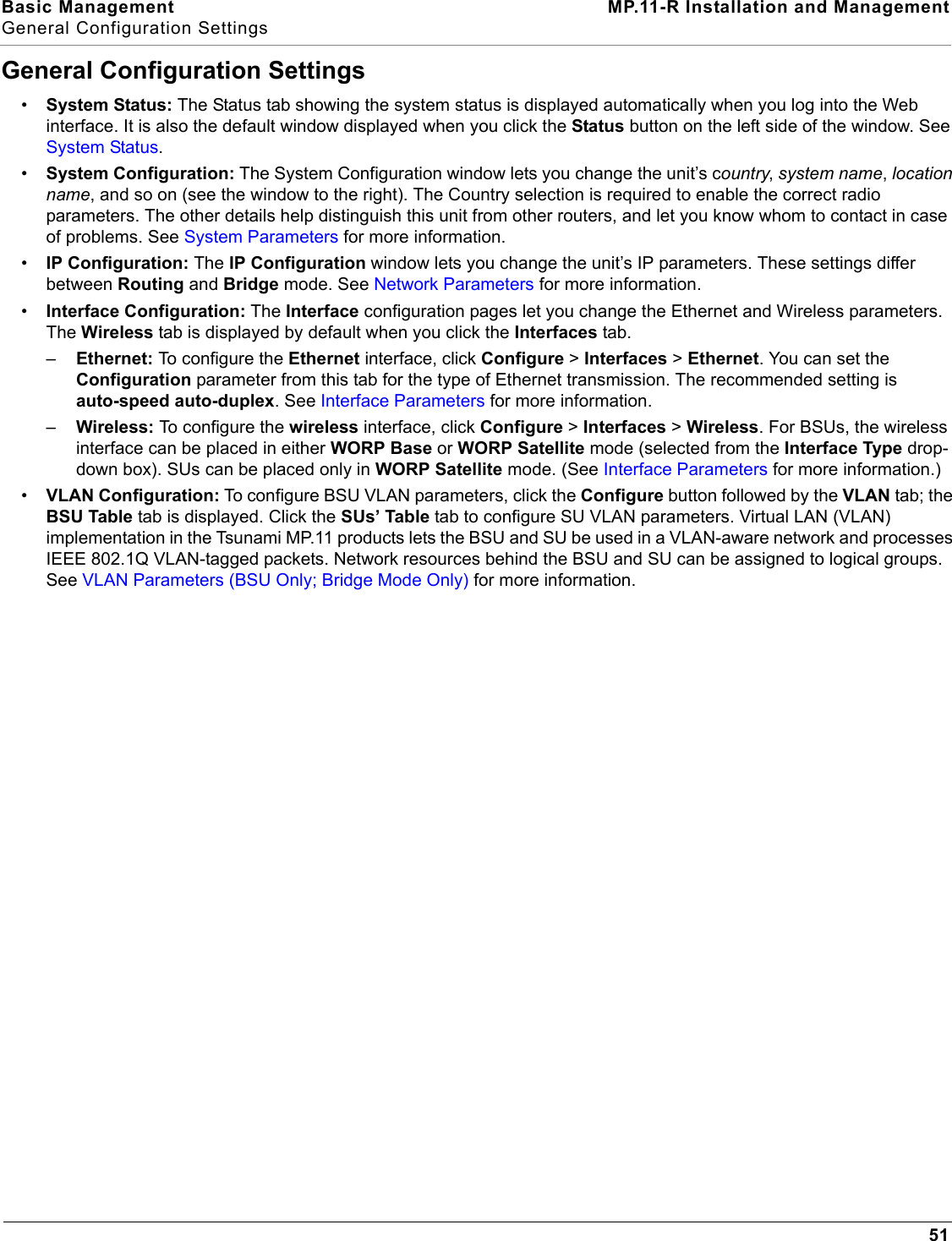
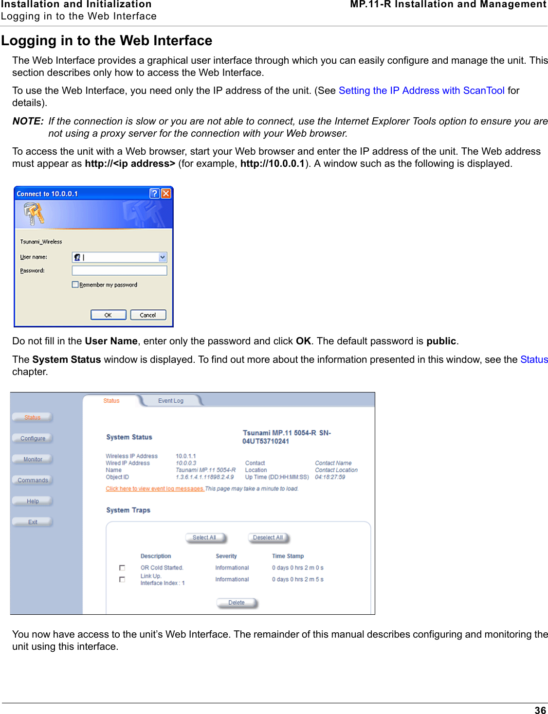
![Installation and Initialization MP.11-R Installation and ManagementHardware Installation33Step 13: Install Documentation and SoftwareTo install the documentation and software on a computer or network:1. Place the CD in a CD-ROM drive. The installer normally starts automatically. (If the installation program does not start automatically, click setup.exe on the installation CD.) 2. Click the Install Software and Documentation button and follow the instructions displayed on the installer windows. The following documentation and software products are installed:– Available from Start > All Programs > Tsunami > MP.11 [Model Name]: • Documentation (in Docs subdirectory):– Installation and Management Guide– Quick Installation Guide– Reference Manual– Safety and Regulatory Guide– Recommended Antenna Guide– Antenna Installation Guide• Online Help• Scan Tool (in Scan Tool subdirectory)• TFTP Server (in TFTP Server subdirectory)NOTE: All of these items are also available from C:\Program Files\Tsunami\MP.11 [Model Name].– Available from C:\Program Files\Tsunami\MP.11 [Model Name]:• Documentation (in Docs folder): See list above• Help files (in Help folder; click on index.htm to access)• TFTP Server and Scan Tool program (in Extras folder)•MIBs (in MIBs folder)](https://usermanual.wiki/Proxim-Wireless/MP11R-ABG.manual-1/User-Guide-790134-Page-33.png)
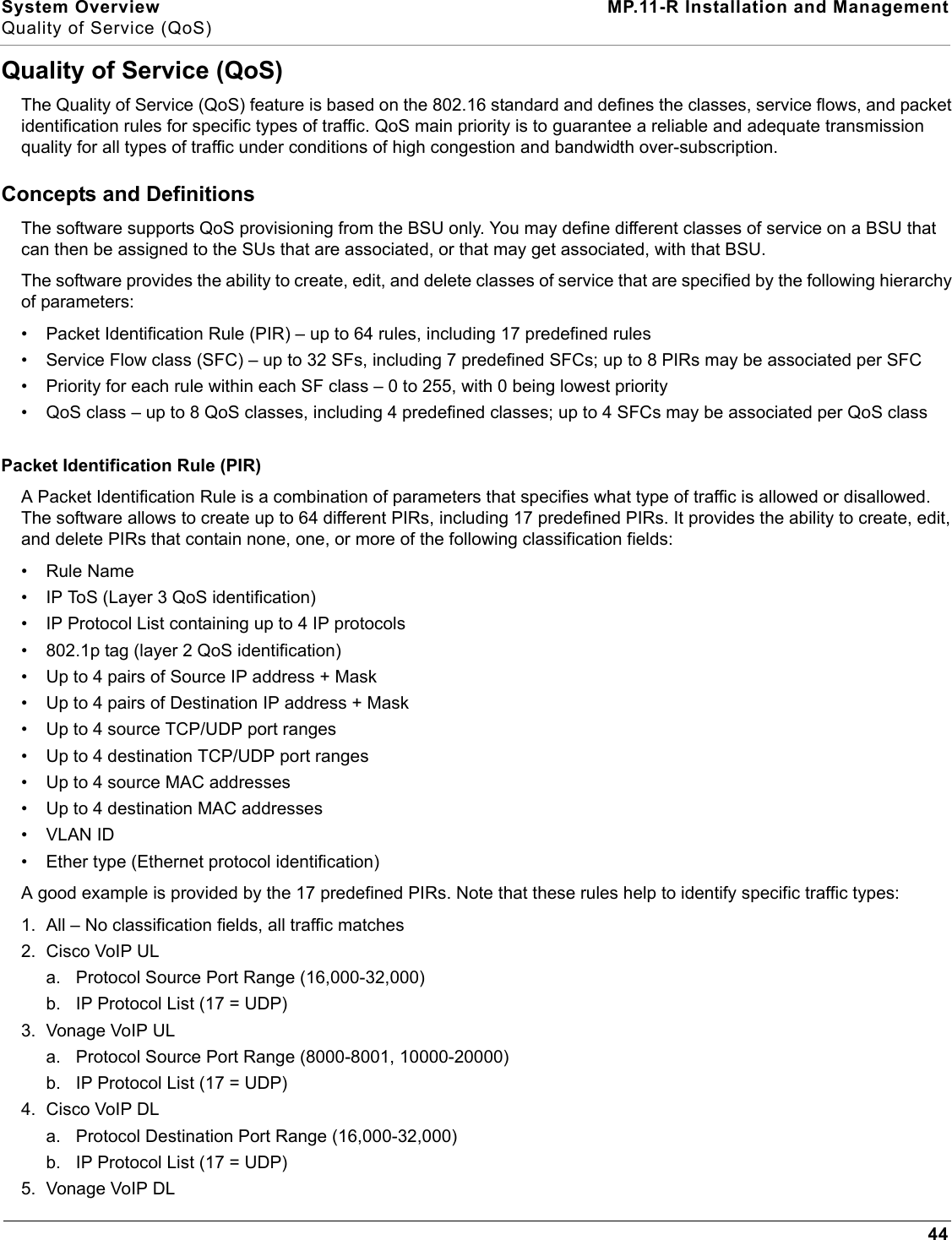
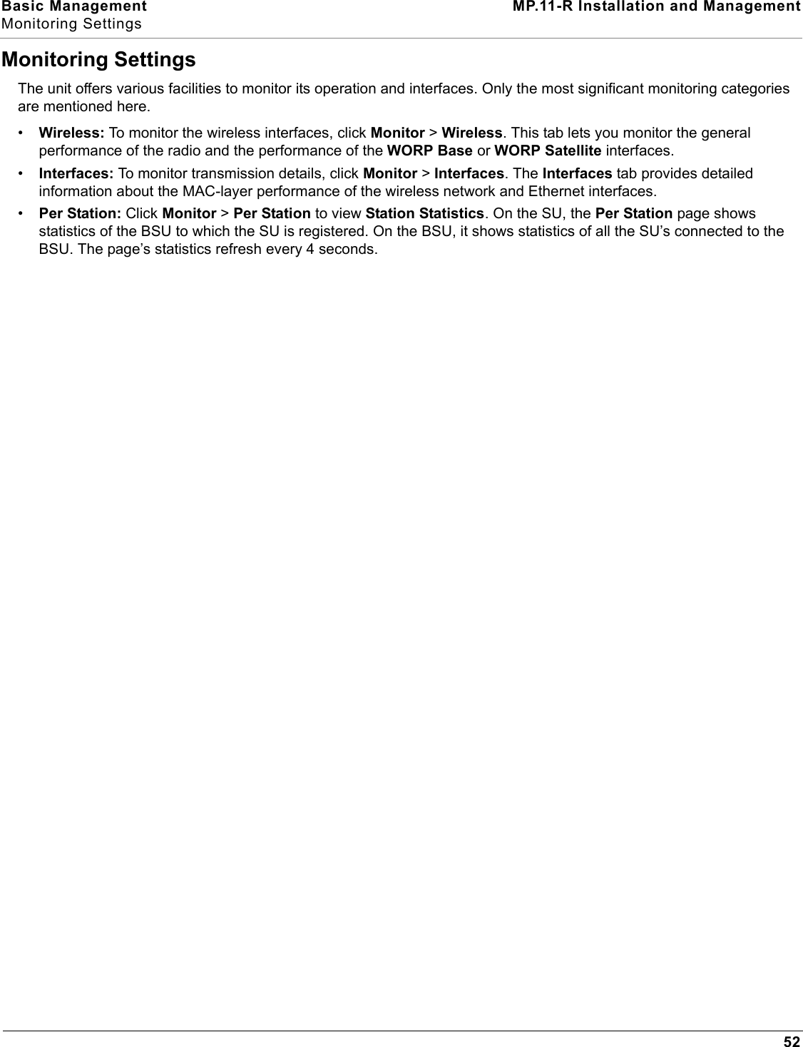
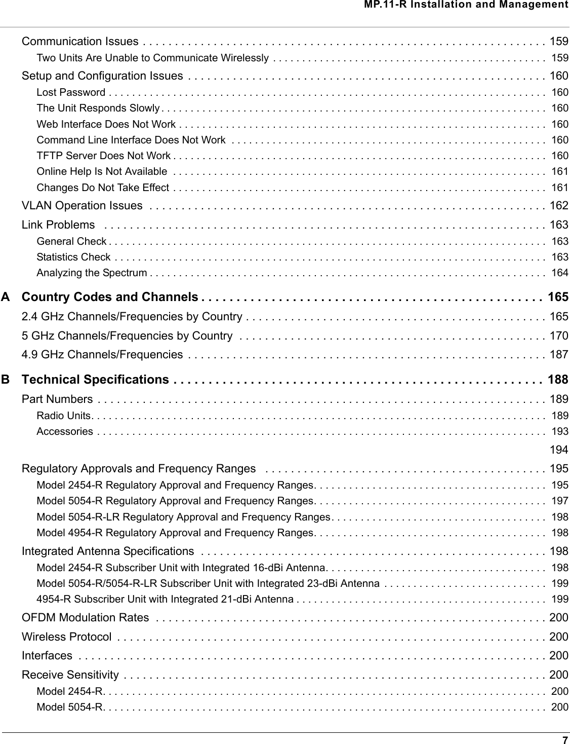
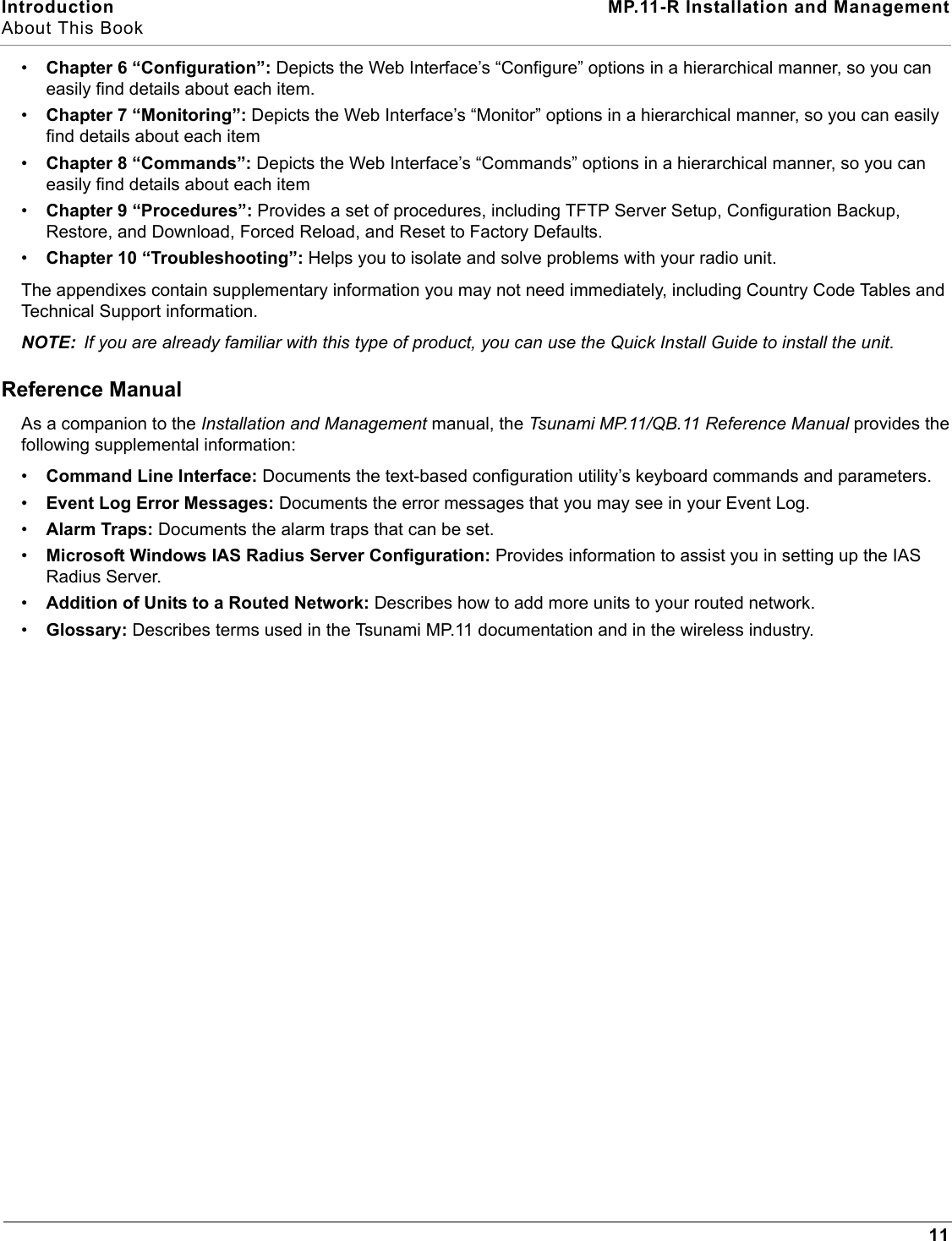
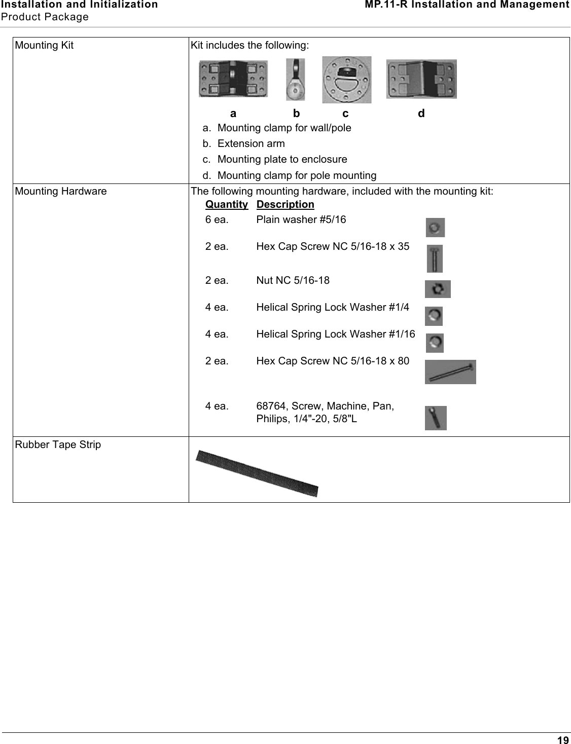
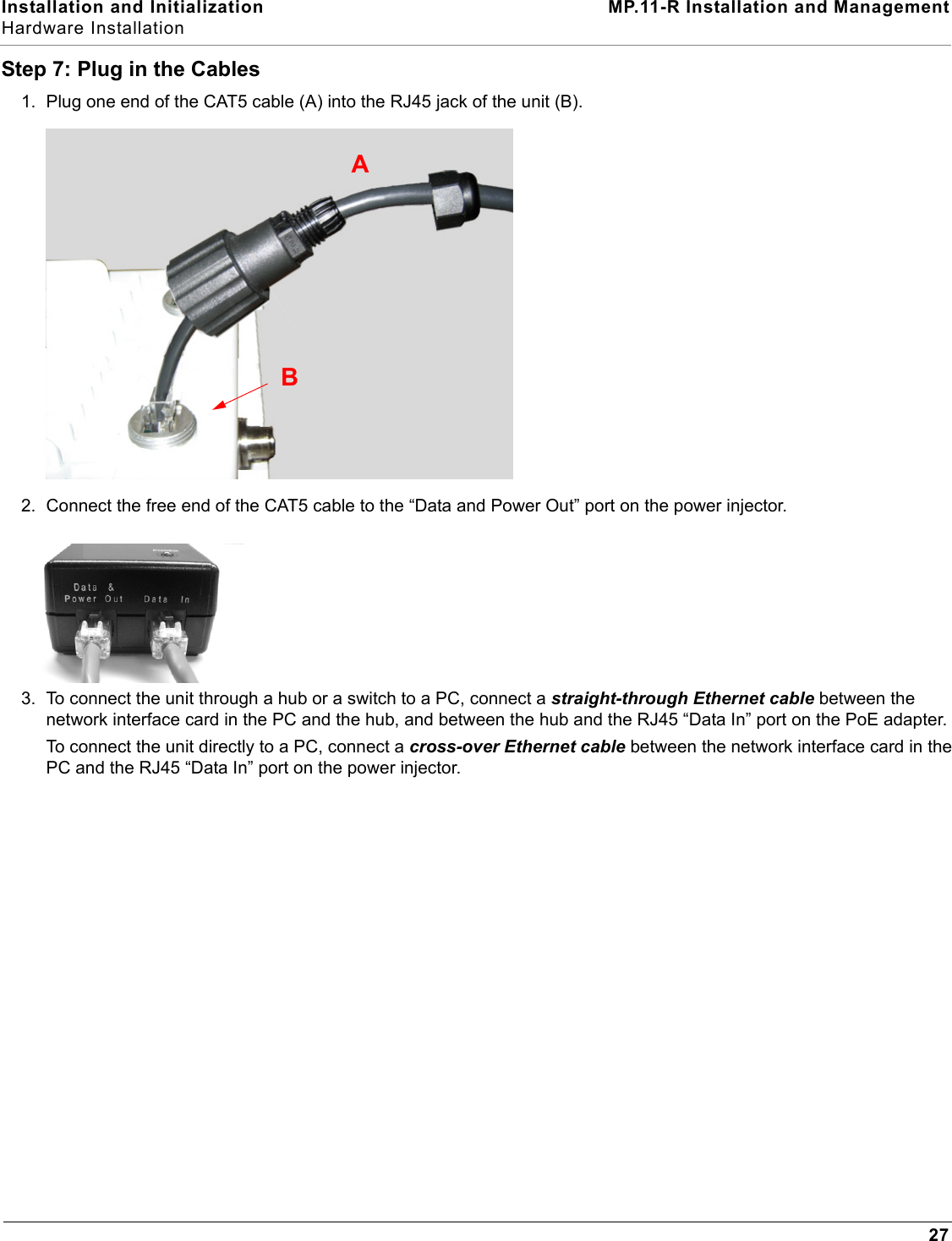
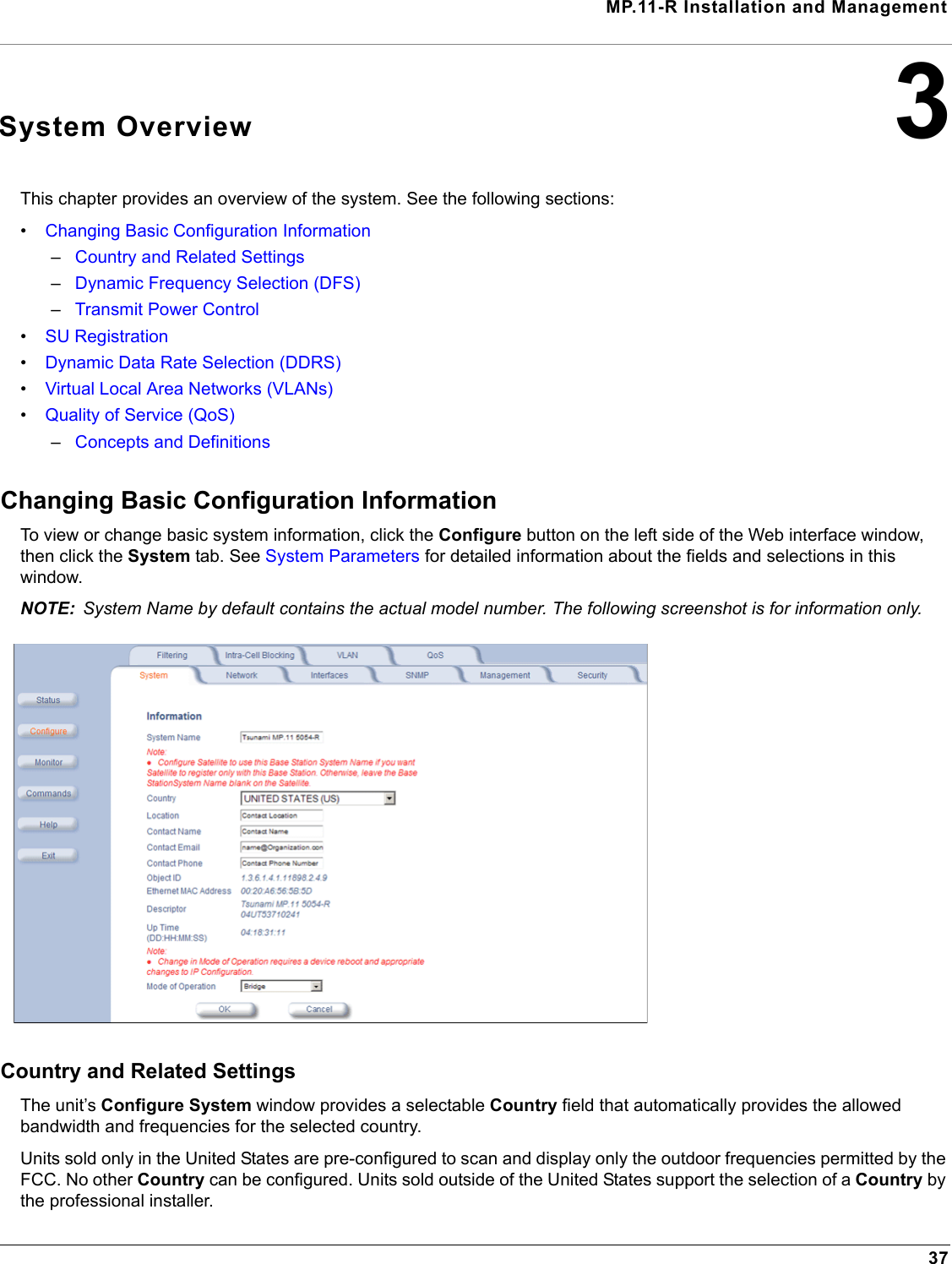
![Installation and Initialization MP.11-R Installation and ManagementInitialization34InitializationConnecting to the unit requires either:• A direct physical connection with an Ethernet cross-over cable or with a serial RS232C cable• A network connection Connecting with a serial connection, allows you to configure and manage the unit with the CLI. Connecting with the other connections allows you to use of the Web Interface and SNMP in addition to the CLI. Using a serial connection, you can access the unit through a terminal emulation program such as HyperTerminal. (See “HyperTerminal Connection Properties” in the Tsunami MP.11/QB.11 Reference Manual.)For all other modes of connection, you will need the IP address of the unit in order to use the Web Interface, SNMP, or the CLI. Because each network is different, an IP address suitable for your network must be assigned to the unit. You must know this IP address to configure and manage the unit through its Web Interface, SNMP, or the CLI. The unit can use either a static or dynamic IP address. The unit either obtains its IP address automatically through DHCP (dynamic IP address) or it must be set manually (static IP address). ScanToolWith ScanTool (a software utility that is included on the product installation CD), you can find out the current IP address of the unit and, if necessary, change it so that is appropriate for your network. The units are shipped with the static IP address 10.0.0.1 configured.ScanTool lets you find the IP address of a Tsunami MP.11-R product by referencing the MAC address in a Scan List, or to assign an IP address if the correct one has not been assigned. The tool automatically detects the units installed on your network segment, regardless of IP address, and lets you configure each unit’s IP settings. In addition, you can use ScanTool to download new software to a unit that does not have a valid software image installed.Setting the IP Address with ScanToolTo discover and set/change the IP address of the unit:1. Run ScanTool on a computer connected to the same LAN subnet as the unit, or a computer directly connected to the unit with a cross-over Ethernet cable. Double-click the ScanTool icon on the Windows desktop to launch the program. If the icon is not on your desktop, click Start > All Programs > Tsunami > MP.11 [Model Name]> Scan Tool.ScanTool scans the subnet for MP.11-R units and displays a list of the units it finds in the Scan List window (shown below). If necessary, click Rescan to re-scan the subnet and update the display. You can assign a new IP address to one unit, even if more than one unit has the same (default) IP address 10.0.0.1, but the new IP address must be unique to allow use of the management interfaces.2. Select the unit for which you want to set the IP address and click Change. The Change dialog window is displayed, as shown below.](https://usermanual.wiki/Proxim-Wireless/MP11R-ABG.manual-1/User-Guide-790134-Page-34.png)
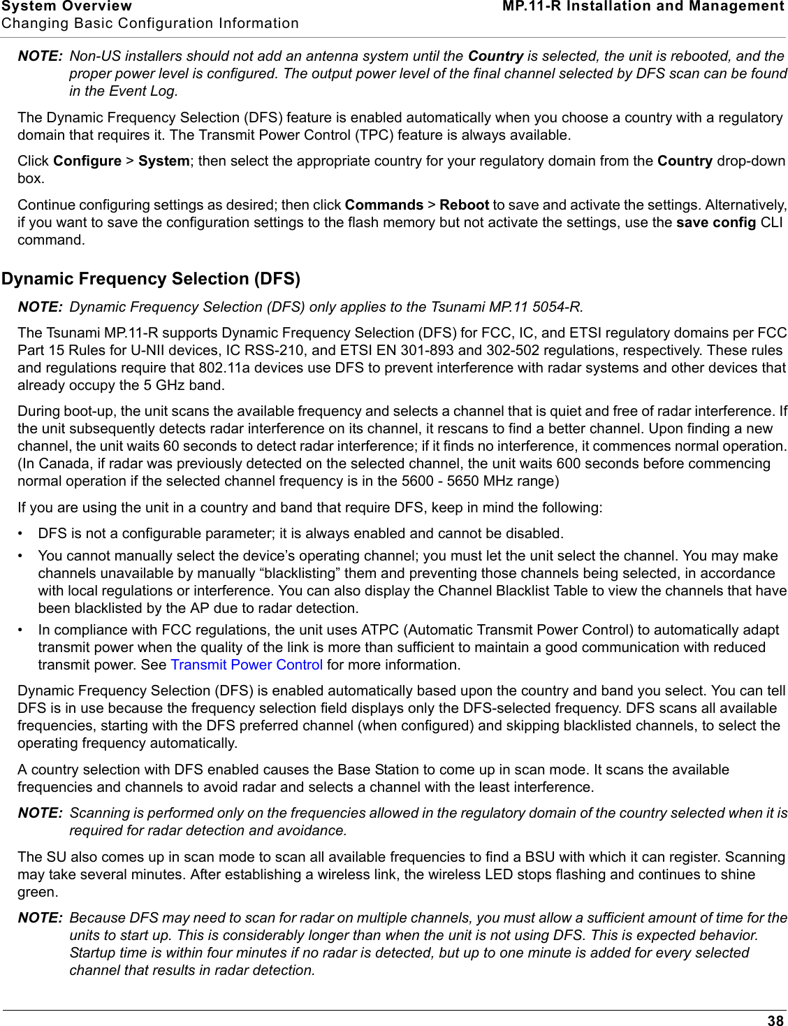
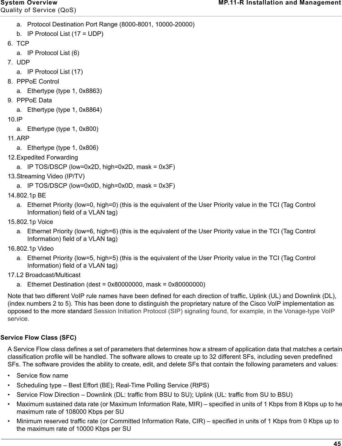
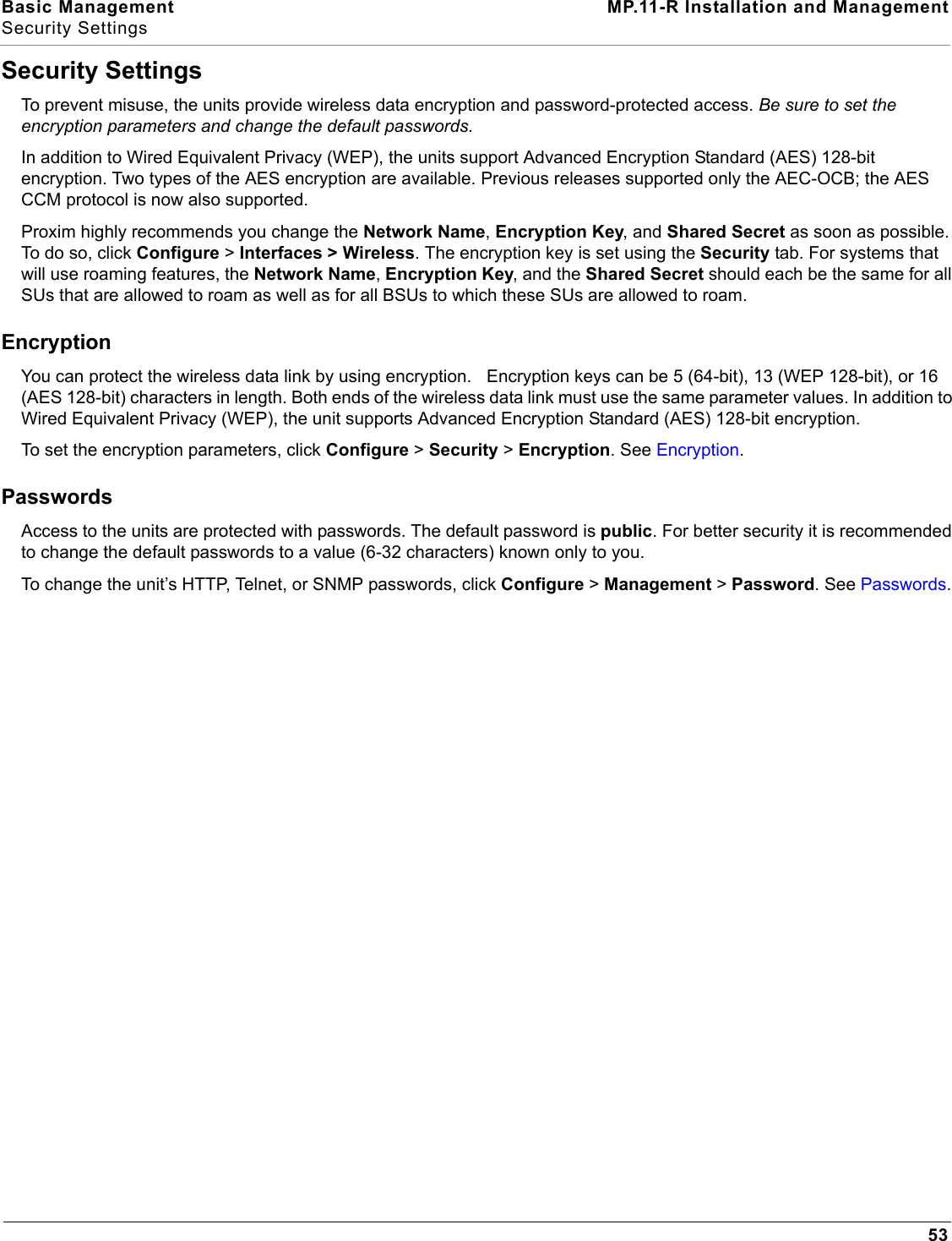
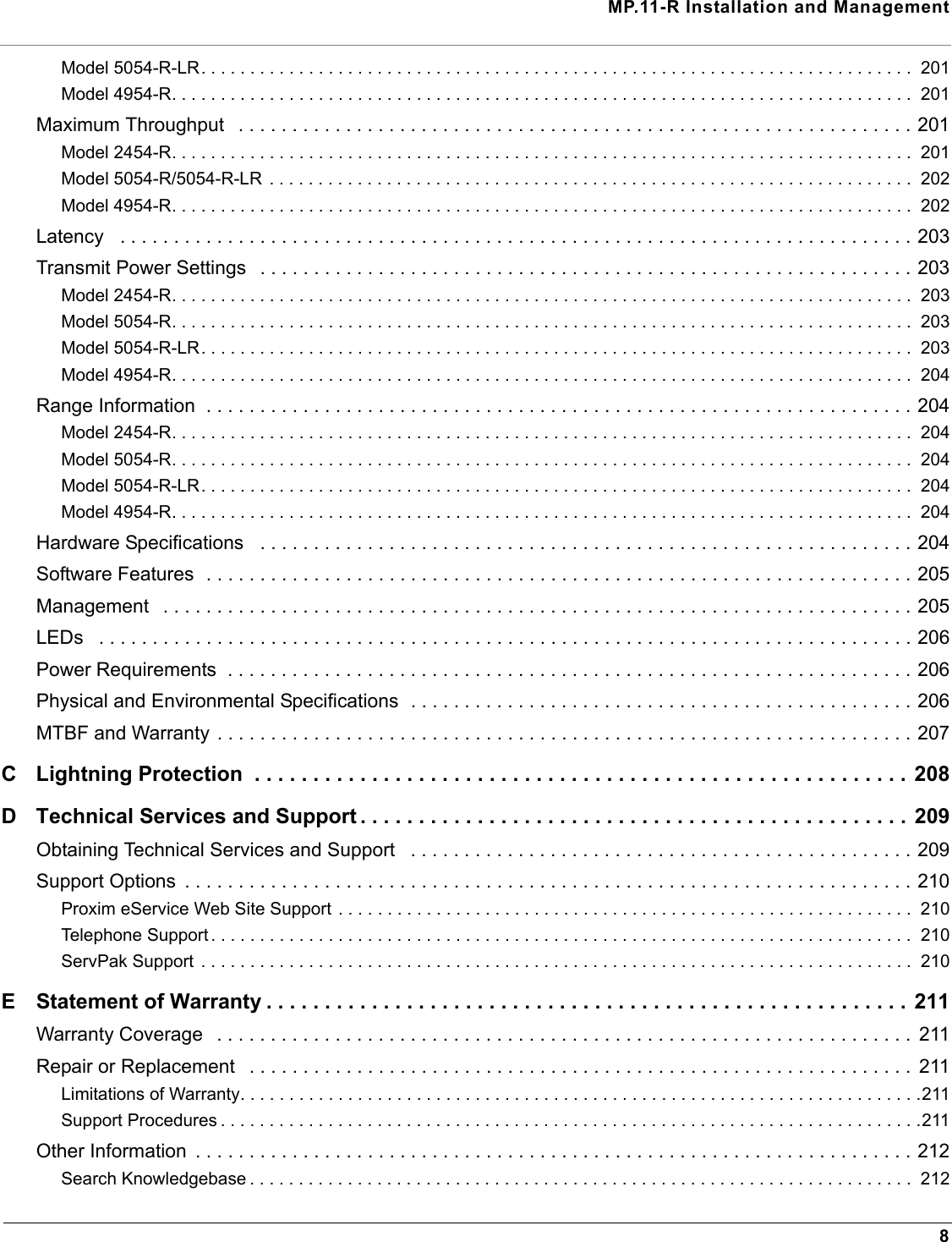
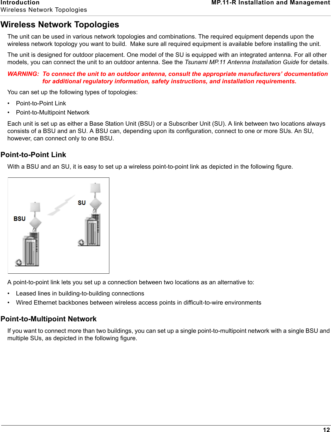
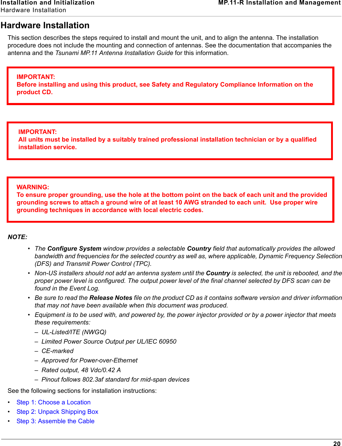
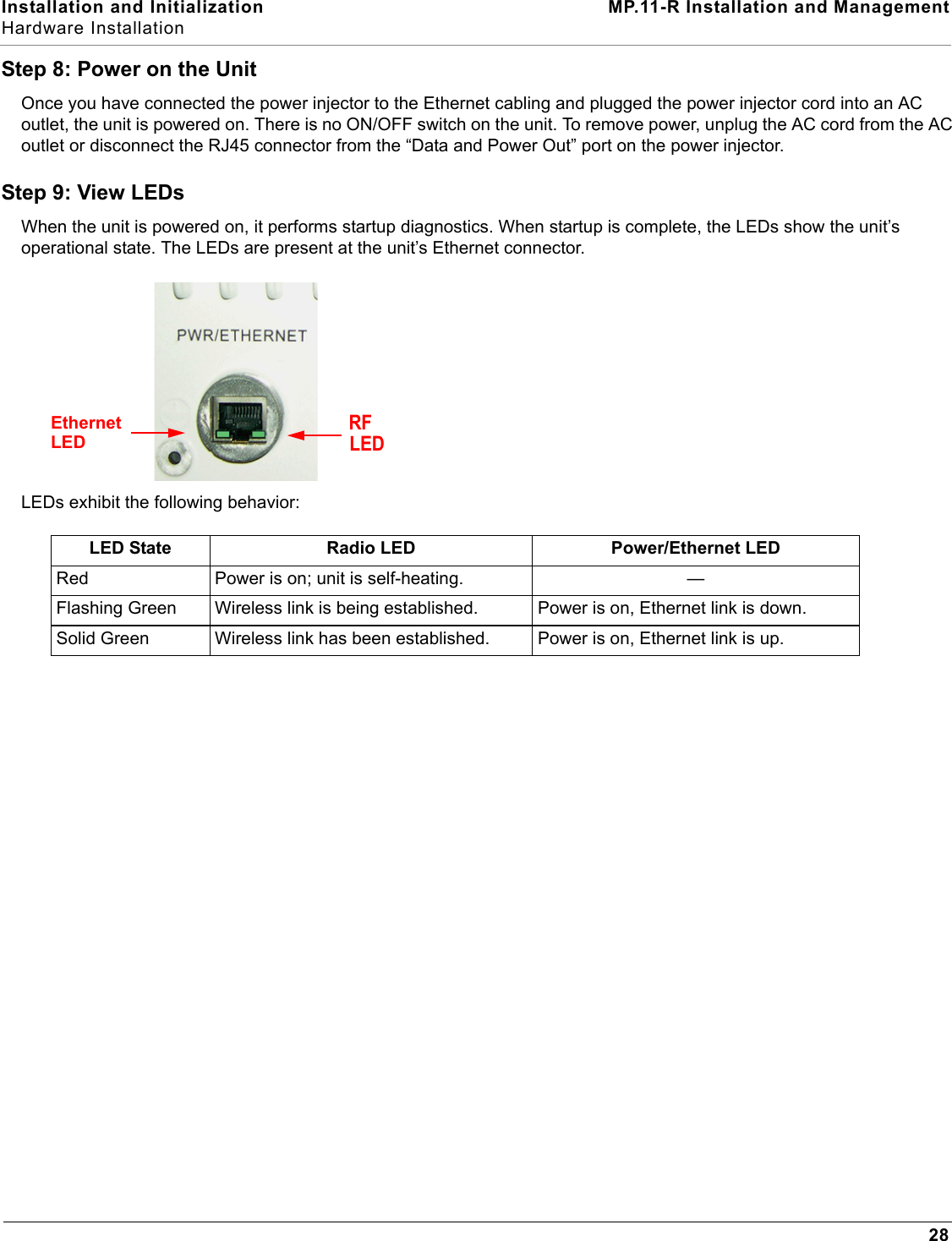
![System Overview MP.11-R Installation and ManagementDynamic Data Rate Selection (DDRS)42Dynamic Data Rate Selection (DDRS)The WORP Dynamic Data Rate Selection (DDRS) lets the BSU and SUs monitor and calculate the remote average signal-to-noise ratio (SNR) and adjust the transmission data rate to an optimal value to provide the best possible throughput according to the current communication conditions and link quality during run-time.Each frame received in the WORP protocol reports the signal and noise level in dBm at which the sender received the previous frame from the receiver, and provides the values to calculate the SNR in dB. SNR is calculated according to this formula then averaged:SNR [dB] = signal level [dBm] – noise level [dBm]Both the BSU and the SUs monitor the remote SNR. The BSU monitors and calculates the average remote SNR for each SU that is registered. An SU monitors and calculates the average remote SNR for the BSU.DDRS is enabled or disabled on the BSU only. This operation requires the BSU to be rebooted. After rebooting, the BSU sends a multicast announcement to all SUs to begin the registration process. During registration, an SU is informed by the BSU whether DDRS is enabled or disabled and it sets its DDRS status accordingly.There are two DDRS data rates that need to be configured when DDRS is enabled:•Default DDRS Data Rate (ddrsdefdatarate): The data rate at which the BSU starts communication with all SUs to begin the registration process (the default is 6 Mbps).•Maximum DDRS Data Rate (ddrsmaxdatarate): The maximum data rate at which the device (BSU or SU) can operate (the default is 54 Mbps).NOTE: The default (BSU only) and maximum (BSU and SU) DDRS data rate values must be configured in the BSU and SUs separately through the CLI or the SNMP interface.See Interface Parameters to configure DDRS.](https://usermanual.wiki/Proxim-Wireless/MP11R-ABG.manual-1/User-Guide-790134-Page-42.png)